lock MITSUBISHI ECLIPSE 1990 Workshop Manual
[x] Cancel search | Manufacturer: MITSUBISHI, Model Year: 1990, Model line: ECLIPSE, Model: MITSUBISHI ECLIPSE 1990Pages: 391, PDF Size: 15.27 MB
Page 290 of 391
__- _ - __ ----____. _ ., _.- -....21-684th GearAUTOMATIC TRANSAXLE
- Transaxle Control
solenoid valve “8”
4th pressure
Icontrol unit
2nd pressure
3rd pressure
Shift control
valviI!
iEx
To N-Dcontrol valve
To rearclutch
Lme pressure
1750233
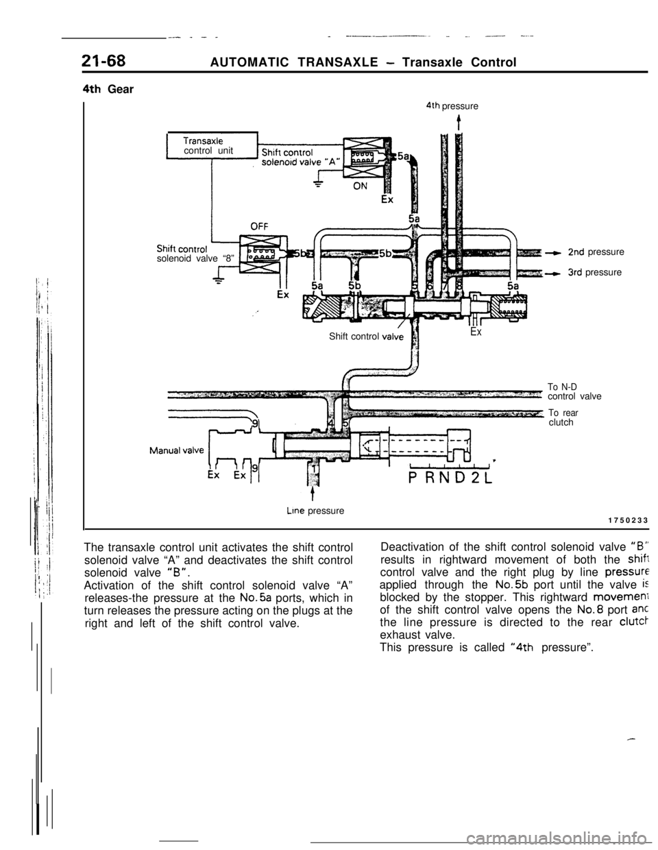
The transaxle control unit activates the shift control
solenoid valve “A” and deactivates the shift control
solenoid valve
“B”.Activation of the shift control solenoid valve “A”
releases-the pressure at the No.5a ports, which in
turn releases the pressure acting on the plugs at the
right and left of the shift control valve.Deactivation of the shift control solenoid valve
“B”results in rightward movement of both the
shiftcontrol valve and the right plug by line
pressureapplied through the No.5b port until the valve
isblocked by the stopper. This rightward movemeni
of the shift control valve opens the No.8 port ant
the line pressure is directed to the rear clutcr
exhaust valve.
This pressure is called
“4th pressure”.
Page 304 of 391
21-82AUTOMATIC TRANSAXLE - Transaxle Control
valve
A
2nd3rdpressure pressure175011:To shift
control
valve#3
land
2nd3rdpressure pressure
175011~LlUpshift from
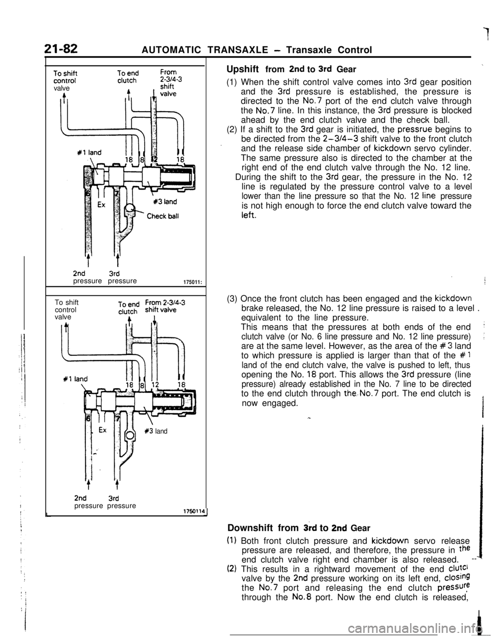
2nd to 3rd Gear\(1) When the shift control valve comes into
3rd gear position
and the
3rd pressure is established, the pressure is
directed to the No.7 port of the end clutch valve through
the No.7 line. In this instance, the
3rd pressure is blocked
ahead by the end clutch valve and the check ball.
(2) If a shift to the
3rd gear is initiated, the pressrue begins to
be directed from the
2-3/4-3 shift valve to the front clutch
and the release side chamber of kickdown servo cylinder.
The same pressure also is directed to the chamber at the
right end of the end clutch valve through the No. 12 line.
During the shift to the
3rd gear, the pressure in the No. 12
line is regulated by the pressure control valve to a level
lower than the line pressure so that the No. 12 line pressureis not high enough to force the end clutch valve toward the
left.(3) Once the front clutch has been engaged and the kickdown
brake released, the No. 12 line pressure is raised to a level .
equivalent to the line pressure.
This means that the pressures at both ends of the end
j
clutch valve (or No. 6 line pressure and No. 12 line pressure)[are at the same level. However, as the area of the
#3 land
to which pressure is applied is larger than that of the
# 1
land of the end clutch valve, the valve is pushed to left, thusopening the No.
18 port. This allows the 3rd pressure (line
pressure) already established in the No. 7 line to be directedto the end clutch through
the..No.7 port. The end clutch is
now engaged.
Downshift from
3rd to 2nd Gear
(1) Both front clutch pressure and kickdown servo release
pressure are released, and therefore, the pressure in
theend clutch valve right end chamber is also released.
--
(2) This results in a rightward movement of the end clutclvalve by the
2nd pressure working on its left end, closingthe
No.7 port and releasing the end clutch pressurethrough the No.8 port. Now the end clutch is released,
I
Page 337 of 391
23-20BODY - Central Door LocksCENTRAL DOOR LOCKS
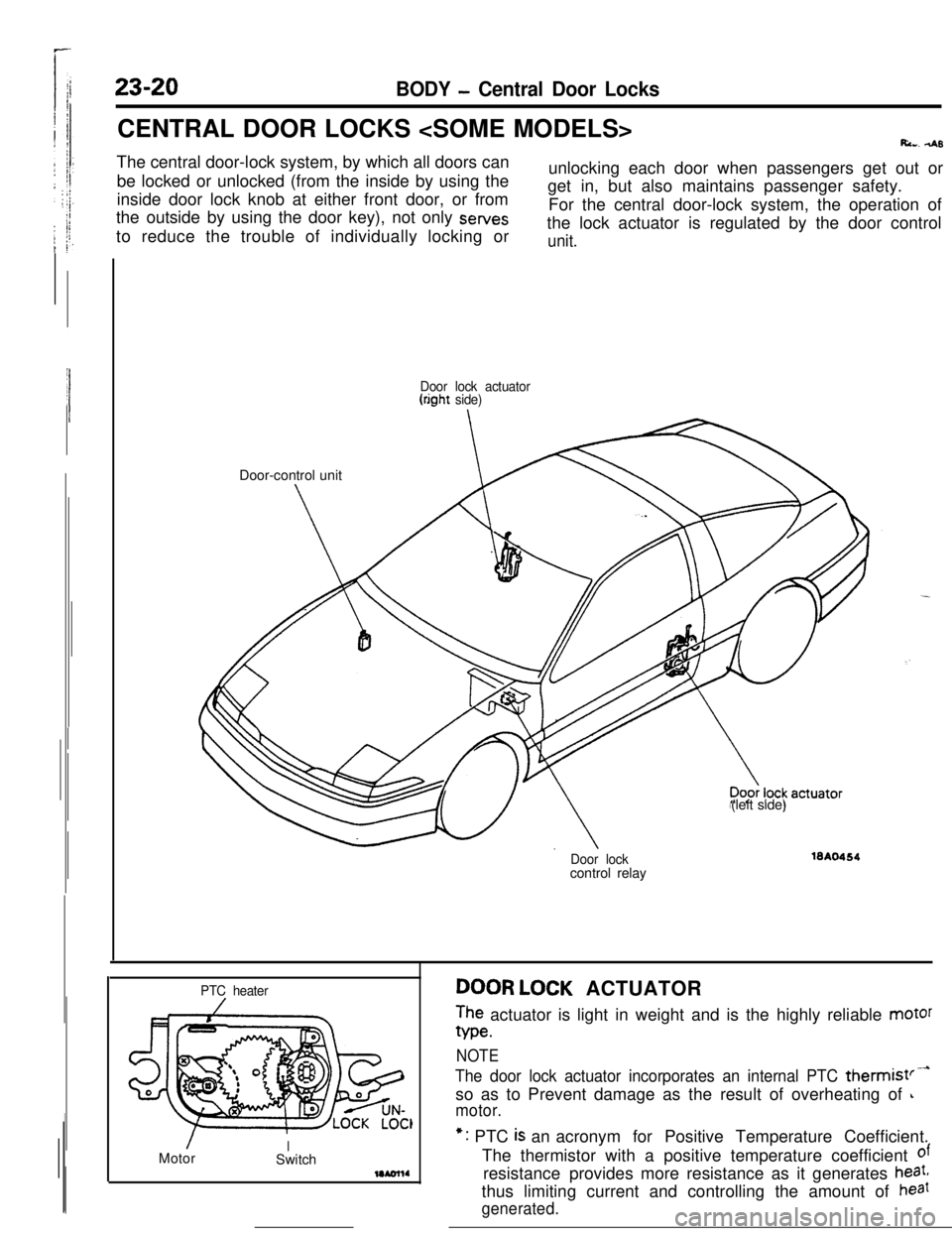
Ri... 4sThe central door-lock system, by which all doors can
be locked or unlocked (from the inside by using the
inside door lock knob at either front door, or from
the outside by using the door key), not only sewes
to reduce the trouble of individually locking orunlocking each door when passengers get out or
get in, but also maintains passenger safety.
For the central door-lock system, the operation of
the lock actuator is regulated by the door control
unit.
Door lock actuator(right side)Door-control unit
(left side)
Door lockcontrol relay16A0464
PTC heater
/MotorISwitchDOOR LOCK ACTUATOR
The actuator is light in weight and is the highly reliable motor
We.
NOTE
The door lock actuator incorporates an internal PTC thermist’-so as to Prevent damage as the result of overheating of
L
motor.*: PTC
is an acronym for Positive Temperature Coefficient.
The thermistor with a positive temperature coefficient
ofresistance provides more resistance as it generates
heat,thus limiting current and controlling the amount of
haat
generated.
Page 338 of 391
BODY - Central Door Locks23-21
IBattery
1IJDoor lock 4Door lockactuator t(left side)actuator
(right side) -Battery
Init !,WF%;$TlON OF THE CENTRAL DOOR
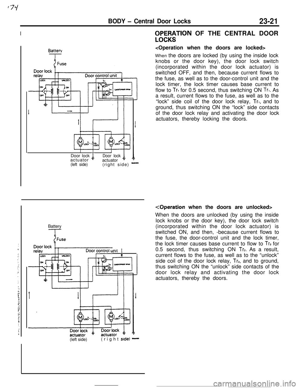
When the doors are locked (by using the inside lock
knobs or the door key), the door lock switch
(incorporated within the door lock actuator) is
switched OFF, and then, because current flows to
the fuse, as well as to the door-control unit and the
lock timer, the lock timer causes base current to
flow to
TrI for 0.5 second, thus switching ON Tr,. As
a result, current flows to the fuse, as well as to the
“lock” side coil of the door lock relay,
Tr,, and to
ground, thus switching ON the “lock” side contacts
of the door lock relay and activating the door lock
actuators, thereby locking the doors.
When the doors are unlocked (by using the inside
lock knobs or the door key), the door lock switch
(incorporated within the door lock actuator) is
switched ON, and then, -because current flows to
the fuse, the door-control unit and the lock timer,
the lock timer causes base current to flow to
Tr? for
0.5 second, thus switching ON
Tr7. As a result,
current flows to the fuse, as well as to the “unlock”
side coil of the door lock relay,
Trp, and to ground,
thus switching ON the “unlock” side contacts of the
door lock relay and activating the door lock
actuators, thereby the doors.
(left side)(right
side) -
Page 339 of 391
23-22BODY - Power Windows
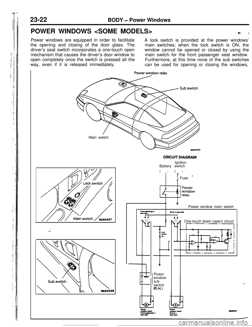
POWER WINDOWS
R’1Power windows are equipped in order to facilitate
A lock switch is provided at the power windows’
the opening and closing of the door glass. The
main switches; when the lock switch is ON, the
driver’s seat switch incorporates a one-touch open
mechanism that causes the driver’s door window towindow cannot be opened or closed by using the
main switch for the front passenger seat window.
open completely once the switch is pressed all the
way, even if it is released immediately.Furthermore, at this time none of the sub switches
can be used for opening or closing the windows,
Main switch
CIRCUIT DIAGRAMIgnition
Battery switch
l-l-
’ 1Fuse ’
Z*,“““”CrPower window main switch
-*W(WlI. _;:
r-
L
--e.
.
I
ELnA
I
Powerwindow
subswitch
(R.H.)
I IOne-touch down (open) circuit
--P’-‘-,
-
Page 348 of 391
BODY - Seat Belts
._-- -
23-31
Shoulder beltI
Lapbelt
IGlove box pad toasty
Knee protector
Guide rail\Fasten switch
\
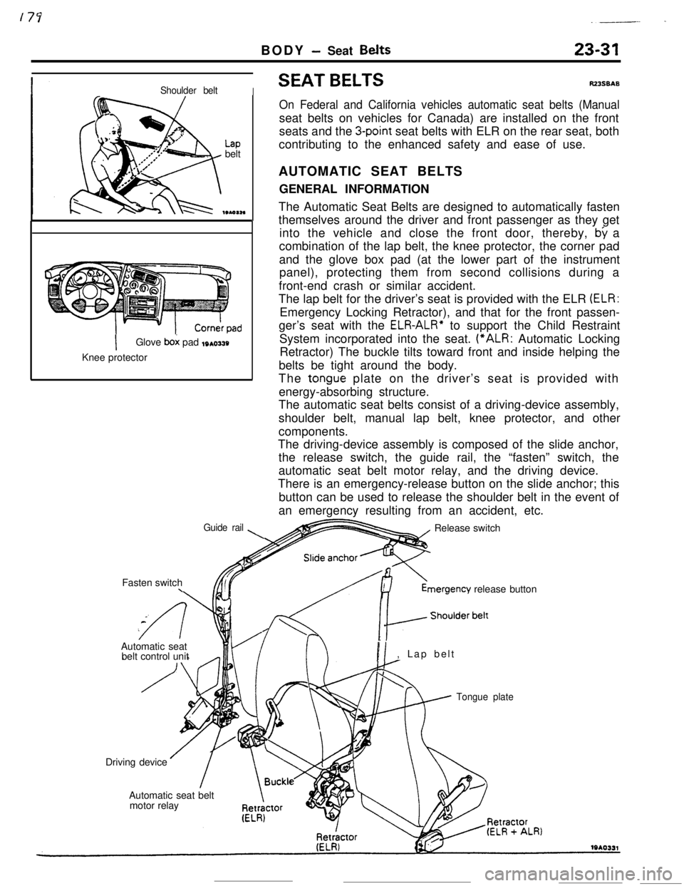
SEAT BELTSRZ3SBAS
On Federal and California vehicles automatic seat belts (Manualseat belts on vehicles for Canada) are installed on the front
seats and the
3-point seat belts with ELR on the rear seat, both
contributing to the enhanced safety and ease of use.
AUTOMATIC SEAT BELTS
GENERAL INFORMATION
The Automatic Seat Belts are designed to automatically fasten
themselves around the driver and front passenger as they get
into the vehicle and close the front door, thereby,
by a
combination of the lap belt, the knee protector, the corner pad
and the glove box pad (at the lower part of the instrument
panel), protecting them from second collisions during a
front-end crash or similar accident.
The lap belt for the driver’s seat is provided with the ELR
(ELR:Emergency Locking Retractor), and that for the front passen-
ger’s seat with the
ELR-ALR” to support the Child Restraint
System incorporated into the seat. (“ALR: Automatic Locking
Retractor) The buckle tilts toward front and inside helping the
belts be tight around the body.
The
tongue plate on the driver’s seat is provided with
energy-absorbing structure.
The automatic seat belts consist of a driving-device assembly,
shoulder belt, manual lap belt, knee protector, and other
components.
The driving-device assembly is composed of the slide anchor,
the release switch, the guide rail, the “fasten” switch, the
automatic seat belt motor relay, and the driving device.
There is an emergency-release button on the slide anchor; this
button can be used to release the shoulder belt in the event of
an emergency resulting from an accident, etc.
Release switchmergency
release button
Automatic seat
belt control unit
PI, Lap belt
Tongue plateDriving device
Automatic seat belt
motor relay
Page 349 of 391
23-32BODY - Seat Belts
OPERATION OF AUTOMATIC SEAT BELTS
The operation of the Automatic Seat Belts is as follows.
(1) The belts fasten itself around the occupant when the front
door is closed with the ignition switch in the “ON” position.
(2) The belts release itself from the occupant when the front
door is opened with the ignition switch in the
*“ON” or
“LOCK” or “ACC” position.
(3) The belts cease to fasten itself around the occupant if the
ignition switch is turned to “LOCK” or “ACC” or when the
front door is opened during the belt motion.
(4) The belts for the driver’s and front passenger’s seats
operate independently of each other.
Lever springStopper, Rod A
Sub paw1
Gear B
Rod B19po37:
Sub’pawlIWO374
IStopperGear AI
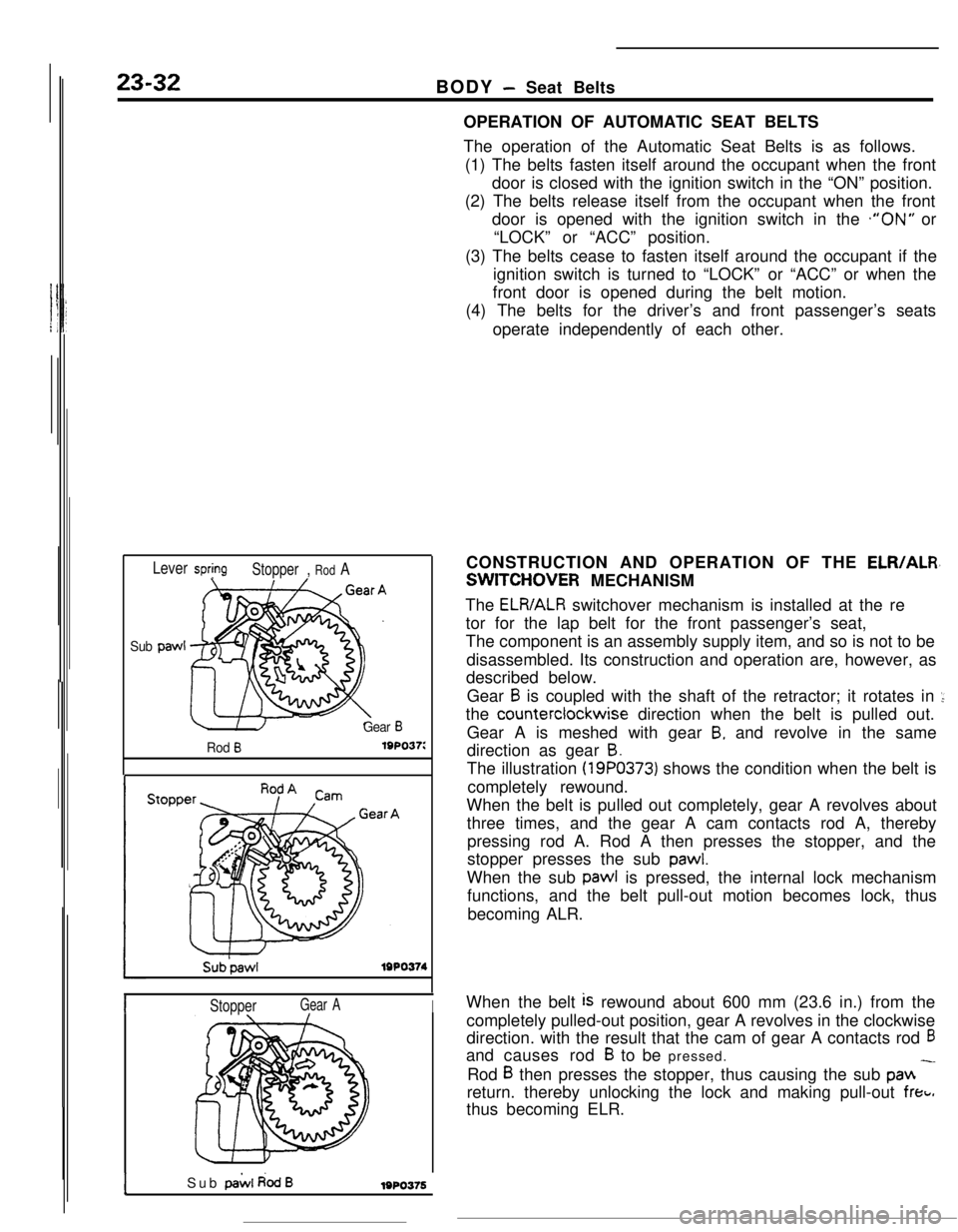
ISub pai.4 dodB1980376CONSTRUCTION AND OPERATION OF THE
ELR/ALR,
SWITCHOVER MECHANISM
The
ELR/ALR switchover mechanism is installed at the re
tor for the lap belt for the front passenger’s seat,
The component is an assembly supply item, and so is not to be
disassembled. Its construction and operation are, however, as
described below.
Gear
B is coupled with the shaft of the retractor; it rotates in ::the counterclockwise direction when the belt is pulled out.
Gear A is meshed with gear
B, and revolve in the same
direction as gear
B.The illustration
(19PO373) shows the condition when the belt is
completely rewound.
When the belt is pulled out completely, gear A revolves about
three times, and the gear A cam contacts rod A, thereby
pressing rod A. Rod A then presses the stopper, and the
stopper presses the sub
pawl.When the sub pawl is pressed, the internal lock mechanism
functions, and the belt pull-out motion becomes lock, thus
becoming ALR.
When the belt
is rewound about 600 mm (23.6 in.) from the
completely pulled-out position, gear A revolves in the clockwise
direction. with the result that the cam of gear A contacts rod
6and causes rod
B to be pressed.
Rod
B then presses the stopper, thus causing the sub pan -return. thereby unlocking the lock and making pull-out
freti.thus becoming ELR.
Page 351 of 391
23-34BODY - Seat Belts
CONSTRUCTION OF DRIVING DEVICE
Slid& anchor
Tabe housingIColiar 1
Drum ALock plate
Gear housing
Gear B
Gear AHousing cover
I
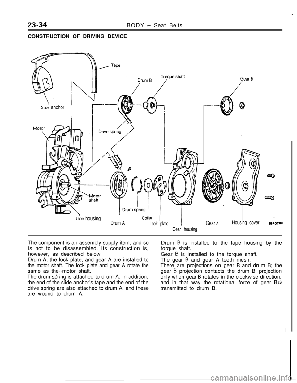
lOPO288The component is an assembly supply item, and so
is not to be disassembled. Its construction is,
however, as described below.
Drum A, the lock plate, and gear A are installed to
the motor shaft. The lock plate and gear A rotate thesame as the--motor shaft.
The drum
&ring is attached to drum A. In addition,
the end of the slide anchor’s tape and the end of the
drive spring are also attached to drum A, and these
are wound to drum A.Drum
B is installed to the tape housing by the
torque shaft.
Gear
B is installed to the torque shaft.
The gear
B and gear A teeth mesh.
There are projections on gear
B and drum B; the
gear
B projection contacts the drum B projection
only when gear
B rotates in the clockwise direction.
and in that way the rotational force of gear
B istransmitted to drum B.
I
Page 352 of 391
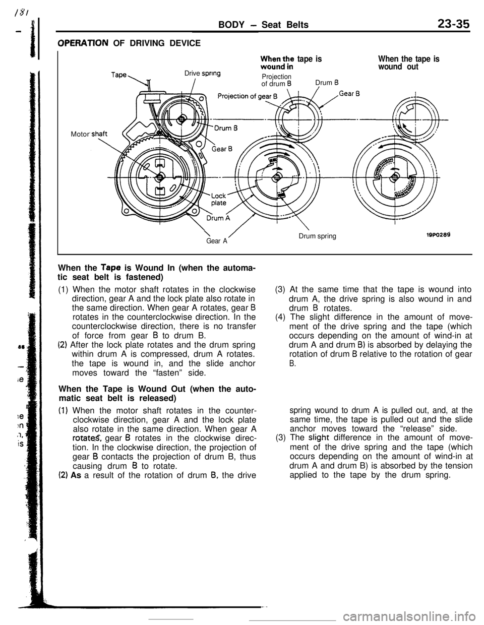
BODY - Seat Belts23-35OPERATlON OF DRIVING DEVICE
TapeDrive spring
Izz;b3;:,e
tape is
Projectionof drum BDrum B/
When the tape is
wound outMotor
\ /Gear ADrum springi9w2a9When the
Tape is Wound In (when the automa-
tic seat belt is fastened)
(1) When the motor shaft rotates in the clockwise
direction, gear A and the lock plate also rotate in
the same direction. When gear A rotates, gear
Brotates in the counterclockwise direction. In the
counterclockwise direction, there is no transfer
of force from gear
B to drum B.
(2) After the lock plate rotates and the drum spring
within drum A is compressed, drum A rotates.
the tape is wound in, and the slide anchor
moves toward the “fasten” side.
When the Tape is Wound Out (when the auto-
matic seat belt is released)
(1) When the motor shaft rotates in the counter-
clockwise direction, gear A and the lock plate
also rotate in the same direction. When gear A
rotate.S, gear B rotates in the clockwise direc-
tion. In the clockwise direction, the projection of
gear
B contacts the projection of drum B, thus
causing drum
B to rotate.
(2) As a result of the rotation of drum 8, the drive(3) At the same time that the tape is wound into
drum A, the drive spring is also wound in and
drum
B rotates.
(4) The slight difference in the amount of move-
ment of the drive spring and the tape (which
occurs depending on the amount of wind-in at
drum A and drum
B) is absorbed by delaying the
rotation of drum
B relative to the rotation of gear
B.
spring wound to drum A is pulled out, and, at thesame time, the tape is pulled out and the slide
anchor moves toward the “release” side.
(3) The slight difference in the amount of move-
ment of the drive spring and the tape (which
occurs depending on the amount of wind-in at
drum A and drum B) is absorbed by the tension
applied to the tape by the drum spring.
Page 356 of 391
BODY - Seat Belts23-39
OPERATlON
Belt Fastening Motion
(1) If the belt is not in the fastening position (the
L.H. or R.H. door latch switch at Door Closed
position; the L.H. or R.H. “fasten” switch at
“ON” position) when the door is closed with the
ignition switch in the “ON” position, the belt
automatically moves to the fastening position.
For the period between the initiation and com-
pletion of the belt’s motion in the fastening
direction, the seat belt warning light either stays
lit or blinks.
Belt Releasing Motion
(1) When the belt is not in the release position, the
L.H. or R.H. release switch is in the “ON”
position, and the left or right door is opened, the
belt will automatically move to the release
position if the ignition switch is at either the
“ON”,“LOCK” or “ACC” position.
For the belt at the driver’s seat side moveover,
the belt will automatically move to the release
position if the
key is taken out while the belt is
fastened.
The buzzer sounds for approximately 0.7 secondsince the start of thebelt’s motion.When the belt is completely fastened, the
“fasten” switch is switched OFF and the motor
stops.(2) With a lapse of approximately 60 seconds after
the belt has stopped its fastening motion due to
foreign object wedged in the mechanism, the
protective timer of the control unit is activated
causing the motor output to the shut off.
When the belt completes its releasing motion,
the L.H. or R.H. release switch is turned OFF,
and the motor stops.
(2)If the belt is still in the process of releasing with
a lapse of approximately 60 seconds after the
start of motion, the protective timer in control
unit is activated causing the motor output to be
shut off.
At the same time, the buzzer sounds for
approximately 0.7 second.
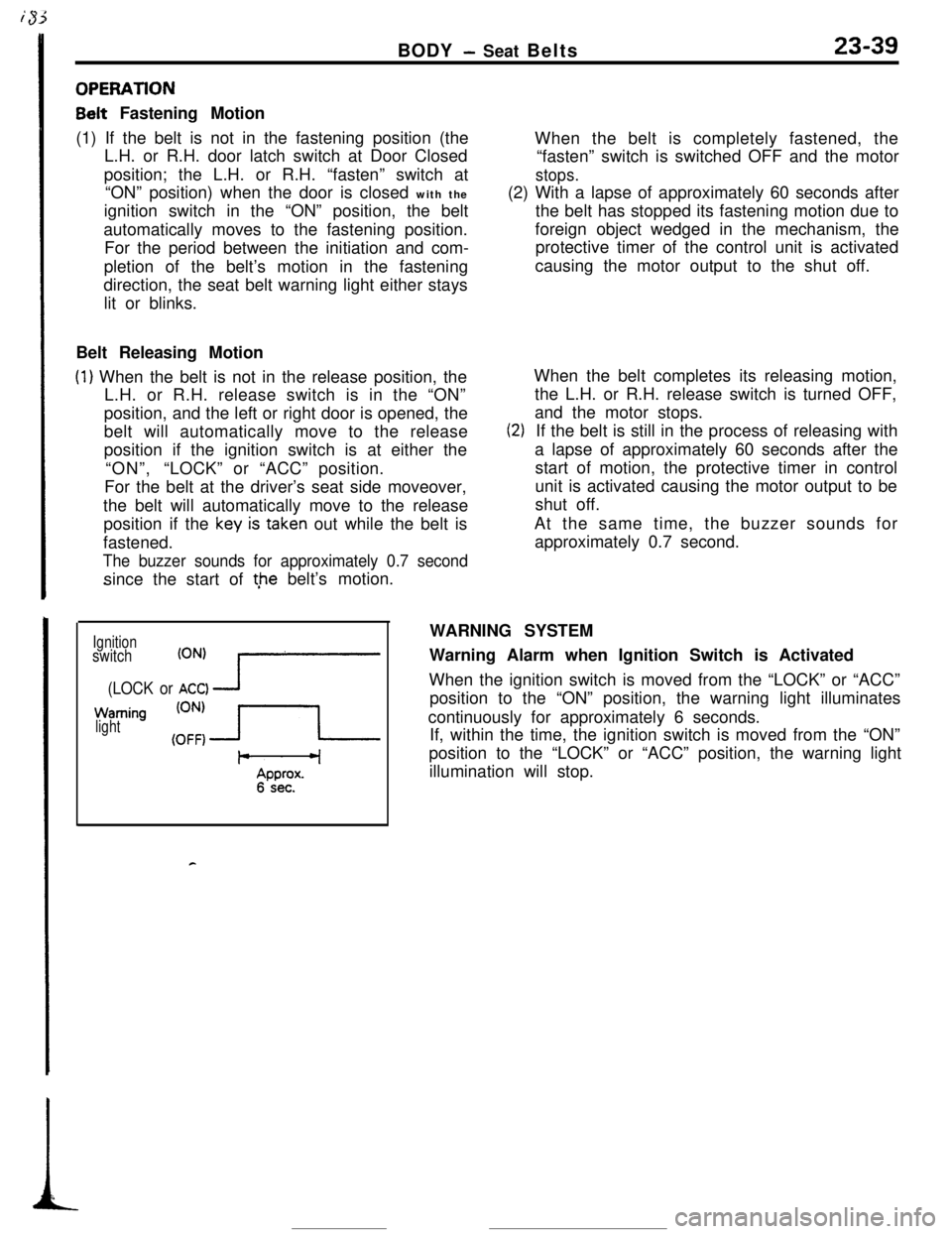
Ignitionswitch
(ONI I------(LOCK or ACC) -J
Warning
light
I-6 sec. ’
cWARNING SYSTEM
Warning Alarm when Ignition Switch is Activated
When the ignition switch is moved from the “LOCK” or “ACC”
position to the “ON” position, the warning light illuminates
continuously for approximately 6 seconds.
If, within the time, the ignition switch is moved from the “ON”
position to the “LOCK” or “ACC” position, the warning light
illumination will stop.