lock MITSUBISHI ECLIPSE 1990 Owner's Manual
[x] Cancel search | Manufacturer: MITSUBISHI, Model Year: 1990, Model line: ECLIPSE, Model: MITSUBISHI ECLIPSE 1990Pages: 391, PDF Size: 15.27 MB
Page 94 of 391
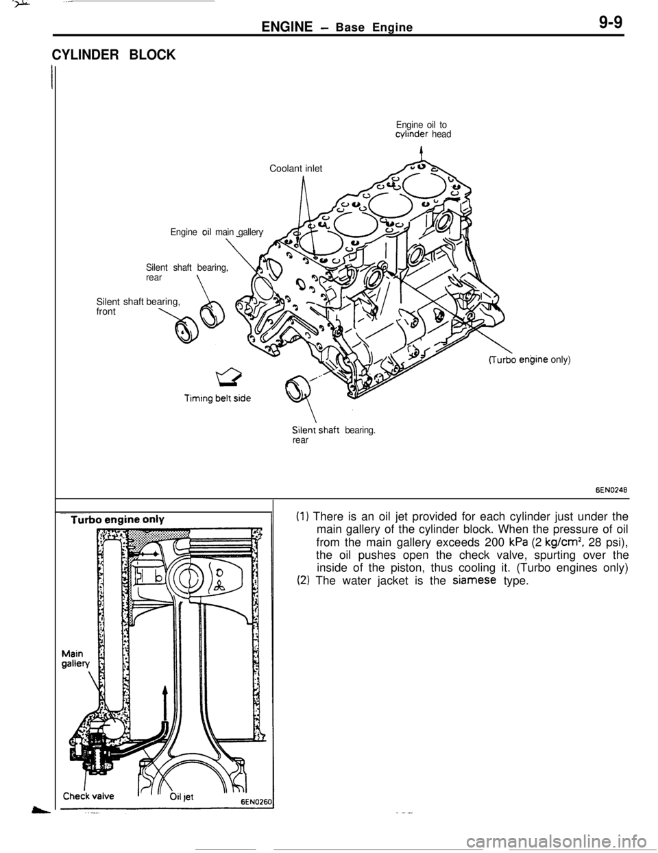
CYLINDER BLOCKENGINE
- Base Engine9-9
Engine oil tocylinder
headCoolant inlet
ASilent
front
Engine oil main gallery
Silent shaft bearing,
rear
\shaft bearing,
A taw
Silenishaft bearing.
rearengine only)
6EN0246
(1) There is an oil jet provided for each cylinder just under the
main gallery of the cylinder block. When the pressure of oil
from the main gallery exceeds 200
kPa (2 kg/cm’, 28 psi),
the oil pushes open the check valve, spurting over the
inside of the piston, thus cooling it. (Turbo engines only)
(2) The water jacket is the Siamese type.
Page 120 of 391
14-8
rFUEL SYSTEM
-Fuel Supply and Fuel Pressure Control
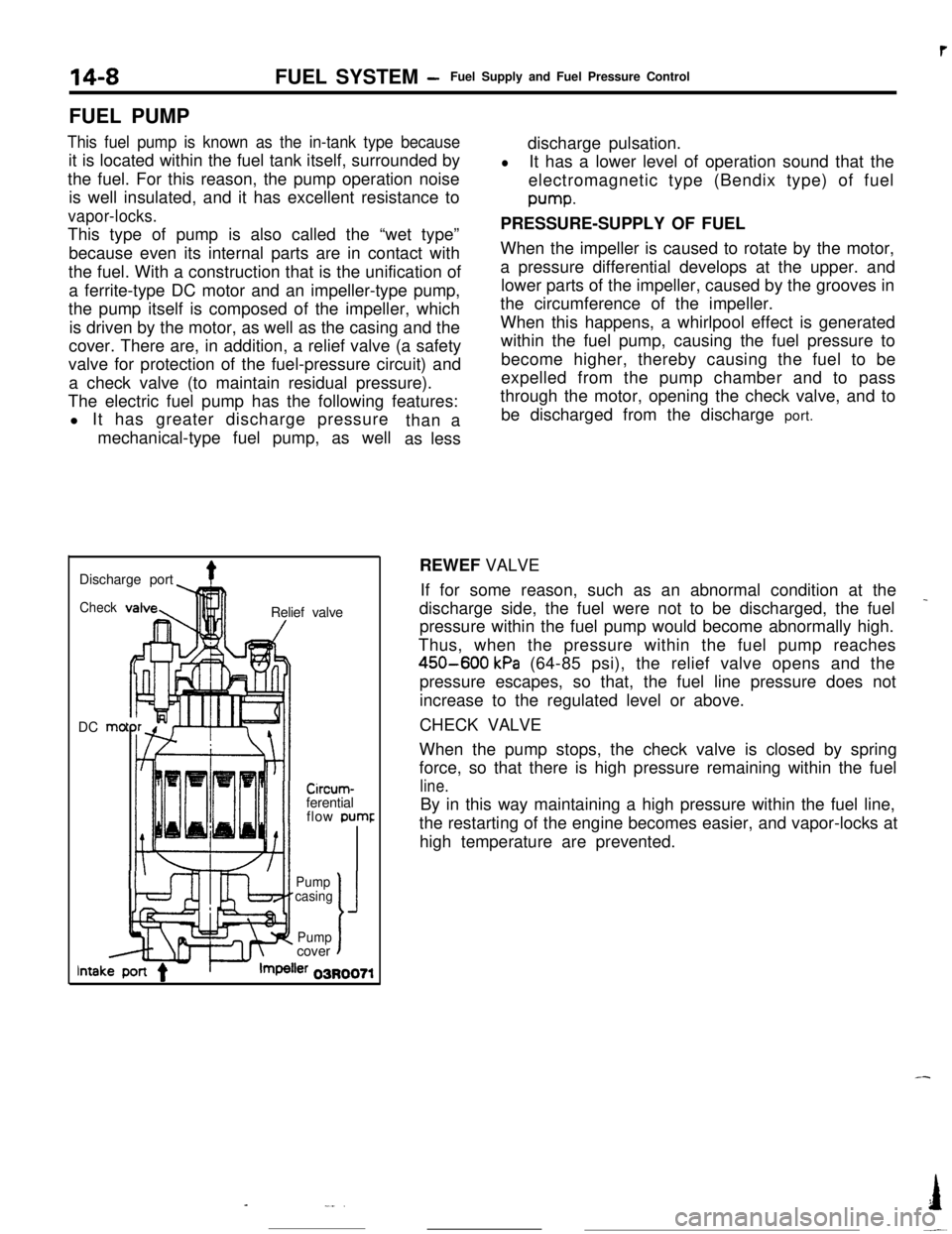
FUEL PUMP
This fuel pump is known as the in-tank type becauseit is located within the fuel tank itself, surrounded by
the fuel. For this reason, the pump operation noise
is well insulated, and it has excellent resistance to
vapor-locks.This type of pump is also called the “wet type”
because even its internal parts are in contact with
the fuel. With a construction that is the unification of
a ferrite-type DC motor and an impeller-type pump,
the pump itself is composed of the impeller, which
is driven by the motor, as well as the casing and the
cover. There are, in addition, a relief valve (a safety
valve for protection of the fuel-pressure circuit) and
a check valve (to maintain residual pressure).
The electric fuel pump has the following features:
l It has greater discharge pressure
mechanical-type fuel pump, as wellthan a
as lessdischarge pulsation.
lIt has a lower level of operation sound that the
electromagnetic type (Bendix type) of fuelpump.
PRESSURE-SUPPLY OF FUEL
When the impeller is caused to rotate by the motor,
a pressure differential develops at the upper. and
lower parts of the impeller, caused by the grooves in
the circumference of the impeller.
When this happens, a whirlpool effect is generated
within the fuel pump, causing the fuel pressure to
become higher, thereby causing the fuel to be
expelled from the pump chamber and to pass
through the motor, opening the check valve, and to
be discharged from the discharge port.
Discharge port
4Check!nRelief valve
DC mo
-lllll1 I/
Circum-ferential
flow pumr
II’ f-Pump
casing
J
Pumpcovert
lntakler 03R0071REWEF VALVE
If for some reason, such as an abnormal condition at the
_discharge side, the fuel were not to be discharged, the fuel
pressure within the fuel pump would become abnormally high.
Thus, when the pressure within the fuel pump reaches
450-600 kPa (64-85 psi), the relief valve opens and the
pressure escapes, so that, the fuel line pressure does not
increase to the regulated level or above.
CHECK VALVE
When the pump stops, the check valve is closed by spring
force, so that there is high pressure remaining within the fuel
line.By in this way maintaining a high pressure within the fuel line,
the restarting of the engine becomes easier, and vapor-locks at
high temperature are prevented.
-
-_..I
-~
Page 126 of 391
14-14
.._~- ---.FUEL SYSTEM
- Sensors
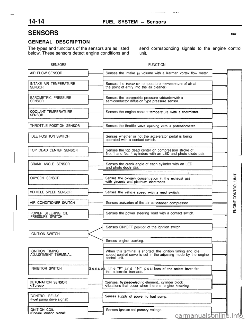
SENSORSRlUGENERAL DESCRIPTION
The types and functions of the sensors are as listedsend corresponding signals to the engine control
below. These sensors detect engine conditions and
unit.
SENSORSFUNCTION
AIR FLOW SENSOR
fSenses the intake arr volume with a Karman vortex flow meter.
INTAKE AIR TEMPERATURE
SENSORSenses the Intake air temperature (temperature of air at
the point of entry into the air cleaner).I
BAROMETRIC PRESSURE
SENSORISenses the barometric pressure faltrtude) wrth a
semiconductor diffusion type pressure sensor.
$;;OOf;T TEMPERATURESenses the engine coolant tern
THROTTLE
POSITISenses the throttle
tI
IDLE POSITION SWITCHSenses whether or not the accelerator pedal is being
operated with a contact switch.
Senses the top dead center on compression stroke of
NO. 1 and No. 4 cylinders with an LED and photo diode pair.
CRANK ANGLE SENSORSenses the crank angle of each cylinder with an LED
and photo diodepair.
T
OXYGEN SENSORSenses
actrvation of the air con
POWER STEERING OIL
PRESSURE SWITCHc-lSenses the power steering ‘load with a contact switch.
IGNITION SWITCHSenses ON/OFF
posrtion of the ignition switch.I
Senses engine cranking.
,
IGNITION TIMING
ADJUSTMENT TERMINALWhen this terminal is shorted, the ignition timing and idle
speed control servo is set in the adjustrng mode by the enginecontrol unit.
INHIBITOR SWITCHSenses the *P” and “N” positthe automatic transaxle.Senses.
by pieto-electric element,. cylinder block
vibrations that occur when there ISengineknocking.
CONTROL RELAY
(Fuel pump drive signal)
lFnorne ianitron sianal!Senses ignrtton coil prIman/ voltage.
Page 128 of 391
14-16FUEL SYSTEM - Sensors
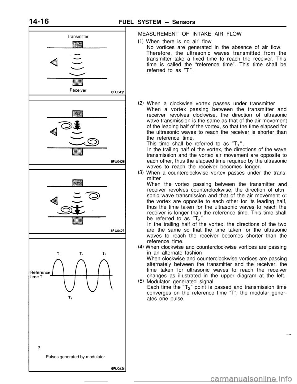
TransmitterMEASUREMENT OF INTAKE AIR FLOW
(1) When there is no air’ flow
No vortices are generated in the absence of air flow.
Therefore, the ultrasonic waves transmitted from the
transmitter take a fixed time to reach the receiver. This
time is called the “reference time”. This time shall be
referred to as
“T”.
Recetver6FUo42!
6FUO426
6f UO42;
TIT1Tl
~tee;ence
9%
T22
Pulses generated by modulator
(2) When a clockwise vortex passes under transmitter
When a vortex passing between the transmitter and
receiver revolves clockwise, the direction of ultrasonic
wave transmission is the same as that of the air movement
of the leading half of the vortex, so that the time elapsed for
the ultrasonic waves to reach the receiver is shorter than
the reference time.
This time shall be referred to as
“T, “.
In the trailing half of the vortex, the directions of the wave
transmission and the vortex air movement are opposite to
each other, thus the elapsed time required by the ultrasonic
waves to reach the receiver becomes longer.
(3) When a counterclockwise vortex passes under the trans-
mitter
When the vortex passing between the transmitter
and-.receiver revolves counterclockwise, the direction of ultr:
sonic wave transmission and that of the air movement
OTthe vortex are opposite to each other for its leading half,
thus the time taken for the ultrasonic waves to reach the
receiver is longer than the reference time. This time shall
be referred to as
“Tz”.In the trailing half of the vortex, the directions of the two
are the same so that the time taken for the ultrasonic
waves to reach the receiver becomes shorter than the
reference time.
(4) When clockwise and counterclockwise vortices are passing
in an alternate fashion
When clockwise and counterclockwise vortices are passing
alternately between the transmitter and the receiver, the
time taken for ultrasonic waves to reach the receiver
changes as illustrated in the upper diagram at the left.
(5) Modulator generated signal
Each time the “T2” point is passed and transmission time
converges on the reference time “T”, the modular gener-
ates one pulse.
-
Page 131 of 391
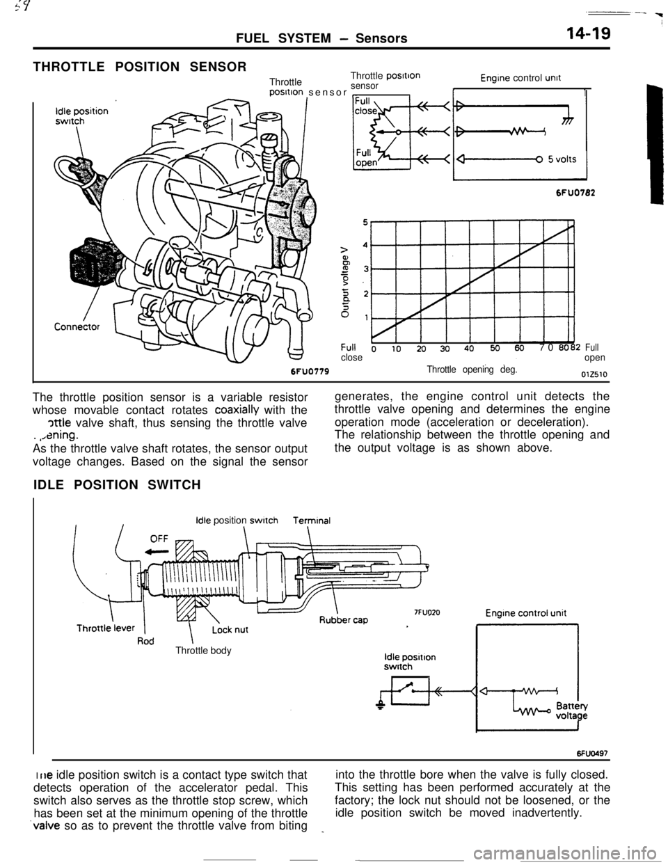
FUEL SYSTEM - Sensors
THROTTLE POSITION SENSOR
ThrottleThrottle
posItIon
sensorposltion sensor
,_Il-
Engine control unit
1
6FU0782
Throttle opening deg.
Full o IO 20 30 4070 0002closeFullopenThe throttle position sensor is a variable resistor
whose movable contact rotates
coaxially with the
cattle valve shaft, thus sensing the throttle valve
.
,,ening.As the throttle valve shaft rotates, the sensor outputgenerates, the engine control unit detects the
throttle valve opening and determines the engine
operation mode (acceleration or deceleration).
The relationship between the throttle opening and
the output voltage is as shown above.
voltage changes. Based on the signal the sensor
IDLE POSITION SWITCH
Idle positionswitchTermtnal
7FUO20Throttle body
Idle positlonswitch
I6Fw497I
rle idle position switch is a contact type switch thatinto the throttle bore when the valve is fully closed.
detects operation of the accelerator pedal. ThisThis setting has been performed accurately at the
switch also serves as the throttle stop screw, whichfactory; the lock nut should not be loosened, or the
has been set at the minimum opening of the throttleidle position switch be moved inadvertently.
‘valve so as to prevent the throttle valve from biting_
Page 137 of 391

FUEL SYSTEM - Sensors14-25Terminal for
ignition timing
adjustment
l-l6FUO51:7
W$ht(/.
Piezo-electncelements
I6FUOSlO
DetonationEngine control
unit
sensor
I-
I t i A-- >--t.--‘-3 -
wt4rlIGNITION TlMlNG ADJUSTMENT TERMINAL
This terminal
is used when adjusting the basic ignition timing or
basic idle speed.
When this terminal is shorted to ground, the engine control unit
cancels the
ignition timing control and idle speed control, and
sets the ignition
timing and idle speed control servos in their
adjusting mode.
For the basic idle speed adjustment, the diagnosis terminal is
also shorted to ground.
DETONATION SENSOR
The detonation sensor is installed at a position where it can
detect, with a high degree of precision, knocking generated at
each cylinder; it detects cylinder block vibrations caused by
knocking, and outputs voltage proportional to the magnitude of
those vibrations.
Because cylinder block vibrations caused by knocking vary
from engine to engine, the engine control unit passes this
through a frequncy filter, detecting only the knocking, thus
resulting in a spark retardation of the ignition timing that
corresponds to the strength of the knocking.
Page 143 of 391
FUEL SYSTEM - Engine Control Unit14-31
r
L
IMPI
Ground
1 Engine control unit
Engine wam-
$b?Stionindicator
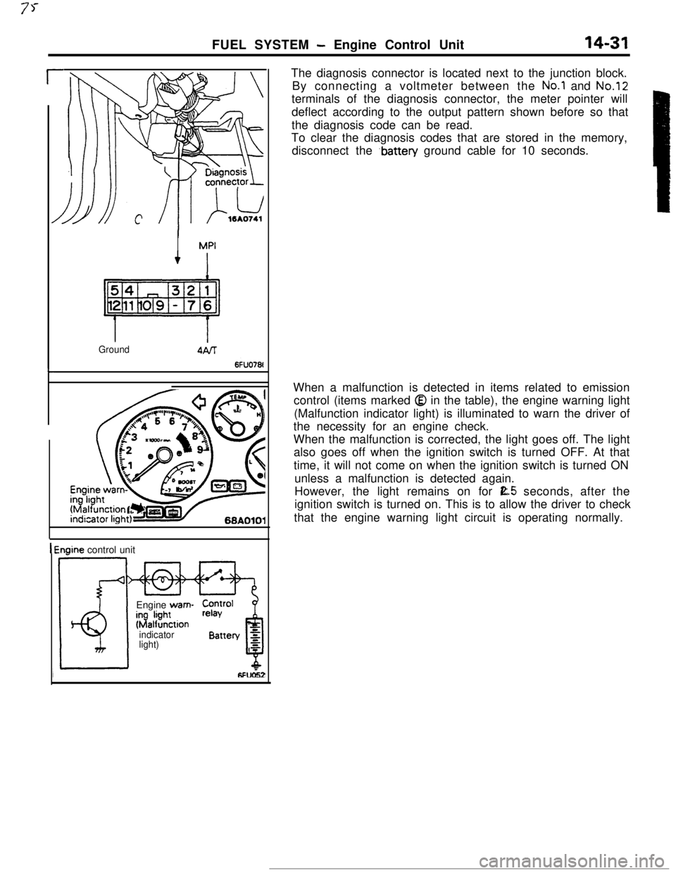
light)The diagnosis connector is located next to the junction block.
By connecting a voltmeter between the
No.1 and No.12terminals of the diagnosis connector, the meter pointer will
deflect according to the output pattern shown before so that
the diagnosis code can be read.
To clear the diagnosis codes that are stored in the memory,
disconnect the
.battery ground cable for 10 seconds.
When a malfunction is detected in items related to emission
control (items marked
Q in the table), the engine warning light
(Malfunction indicator light) is illuminated to warn the driver of
the necessity for an engine check.
When the malfunction is corrected, the light goes off. The light
also goes off when the ignition switch is turned OFF. At that
time, it will not come on when the ignition switch is turned ON
unless a malfunction is detected again.
However, the light remains on for
E.5 seconds, after the
ignition switch is turned on. This is to allow the driver to check
that the engine warning light circuit is operating normally.
Page 160 of 391
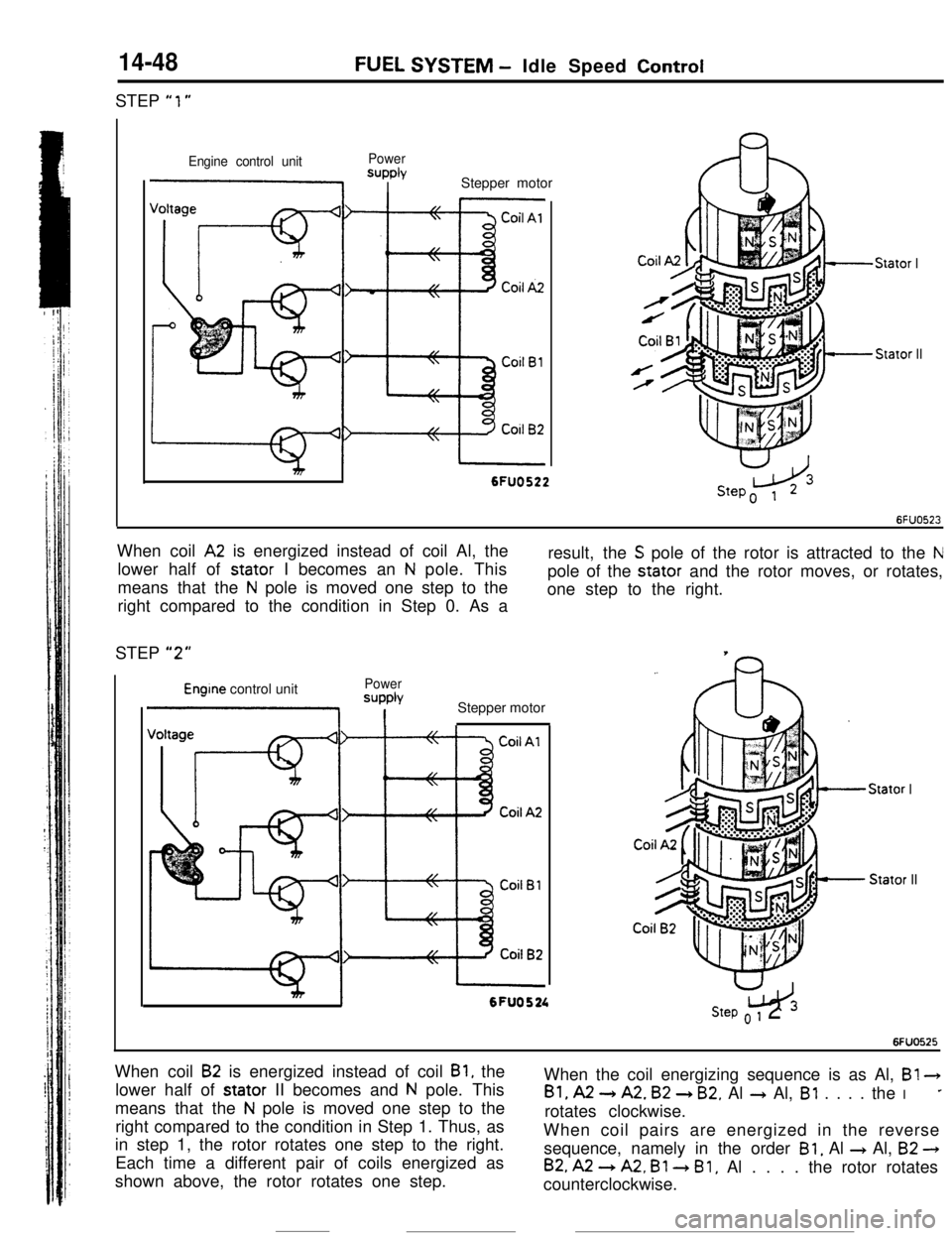
14-48STEP
“1”
FUEL SYSTEM - Idle Speed Control
Engine control unitPowerSUPPlYI IStepper motor
Stator I
Stator II
I6FUO522When coil
A2 is energized instead of coil Al, the
lower half of stator I becomes an
N pole. This
means that the
N pole is moved one step to the
right compared to the condition in Step 0. As aresult, the
S pole of the rotor is attracted to the Npole of the stator and the rotor moves, or rotates,
one step to the right.
STEP
“2”
Engine control unitPower
=JPPb
1 IStepper motor
Stator IStator II
mI6FU0524w3Step o 1 2
6FUO525When coil
B2 is energized instead of coil Bl, the
lower half of stator II becomes and
N pole. This
means that the
N pole is moved one step to the
right compared to the condition in Step 1. Thus, as
in step 1, the rotor rotates one step to the right.
Each time a different pair of coils energized as
shown above, the rotor rotates one step.When the coil energizing sequence is as Al, B!
3
Bl, A2 -) A2. B2 + B2. Al + Al, Bl . . . . the I*rotates clockwise.
When coil pairs are energized in the reverse
sequence, namely in the order
Bl, Al + Al, B2 -)
B2, A2 --) A2, Bl 3 Bl, Al . . . . the rotor rotates
counterclockwise.
Page 172 of 391
-.
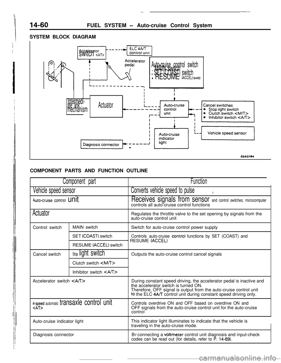
14-60FUEL SYSTEM - Auto-cruise Control System
SYSTEM BLOCK DIAGRAM
---
f?,: 0,
,’
vi
switch cpJT>
Auto-cruise control switch. MAIN switchl SET (COAST) switchl RESUME (ACCEL) switc
I
Intermedi-ate linkActuator
mechanismCOMPONENT PARTS AND FUNCTION OUTLINE
Component part
Vehicle speed sensor
6\uto-cruise control unit
Function
Converts vehicle speed to pulse,
Receives signals from sensor and control switches; microcomputercontrols all auto-cruise control functions
ActuatorRegulates the throttle valve to the set opening by signals from the
auto-cruise control unit
Control switchMAIN switch
Switch for auto-cruise control power supply
SET
(COAST) switchControls auto-cruise control functions by SET (COAST) and
1 RESUME (ACCELIRESUME (ACCEL) switch
Cancel switch
Stop light switchClutch switch
Inhibitor switch CA/T>
Accelerator switch
During constant speed driving, the accelerator pedal is inactive and
the accelerator switch is turned ON.
Therefore, OFF signal is output from the auto-cruise control unitto the ELC
4A/T control unit during constant speed driving only.
4-I-Ed automatic transaxle control unitControls overdrive ON and OFF based on overdrive ON andOFF signals from the auto-cruise control unit for the auto-cruise
controlAuto-cruise indicator lightThis indicator light illuminates to indicate that the vehicle is
traveling in the auto-cruise mode.
Diagnosis connectorBY connecting a voltmeter control unit diagnosis and input-check
codes can be read out (for details, refer to P. 14-69).
Page 173 of 391
F
FUEL SYSTEM -Auto-cruise Control System'l4-61
AUTOCRUISE CONTROL UNIT
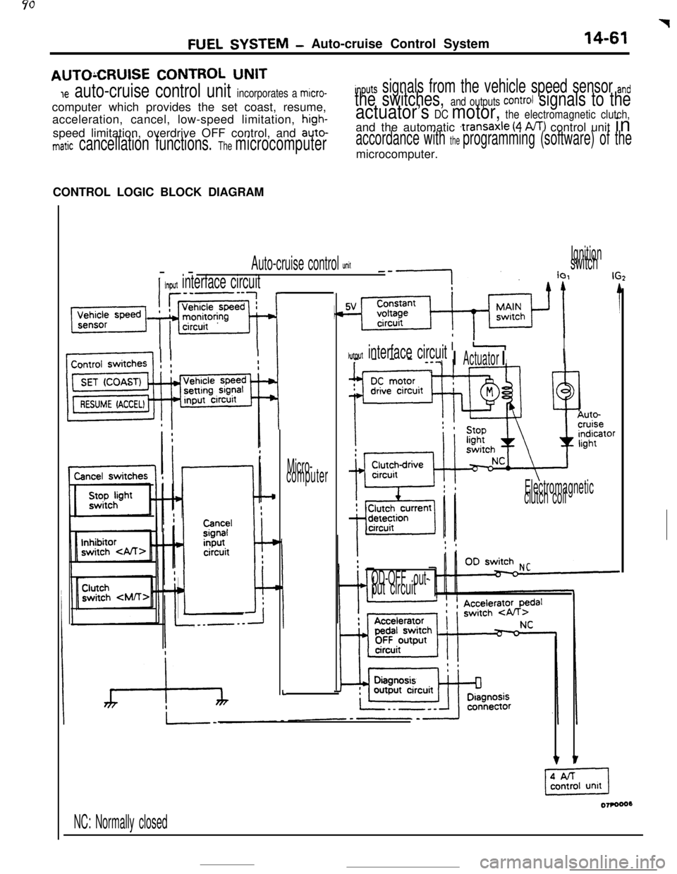
Je auto-cruise control unit incorporates a micro-computer which provides the set coast, resume,
acceleration, cancel, low-speed limitation,
high-speed limitation, overdrive OFF control, and
auto-
matic cancellation functions. The microcomputer
inputs signals from the vehicle speed sensor and
the switches, and outputs Control signals to the
actuator’s DC motor, the electromagnetic clutch,and the automatic
.transaxle (4 A/T) control unit in
accordance with the programming (software) of themicrocomputer.
CONTROL LOGIC BLOCK DIAGRAM
--
Auto-cruise control UnitIgnitionswitcha.-.
I
Input interface circuit
piz7q.f~~
I
L
Micro-
computer
jutput interface circuitIr--lI----
--7I IActuatorI
Electromagnetic
clutch coil
OD-OFF out-
put circuit
NC: Normally closed