engine oil MITSUBISHI ECLIPSE 1991 Service Manual
[x] Cancel search | Manufacturer: MITSUBISHI, Model Year: 1991, Model line: ECLIPSE, Model: MITSUBISHI ECLIPSE 1991Pages: 1216, PDF Size: 67.42 MB
Page 477 of 1216

FUEL SYSTEM - Troubleshootinn
-.
_-
AIR FLOW SENSORr
INTAKK AlN AlNTENPERAIURE PLOUEENBOR BENBORA-36
q_-____-____--_ -----------5
T
14
c
----.19
Ic
21
lfl
2ON3OFF
Y
IDLESWITCH=4 EGR TEMPERATURE ENGINETHROTTLE
fi %i%kES FORPOSITION
CALIFORNIA)
B-08 mB-30 I
Ia
{mc
B-05
mPOWER
STEERING OIL
Pl?l?f;#RE
KX35-AC-UOBlBA-NC
Page 515 of 1216
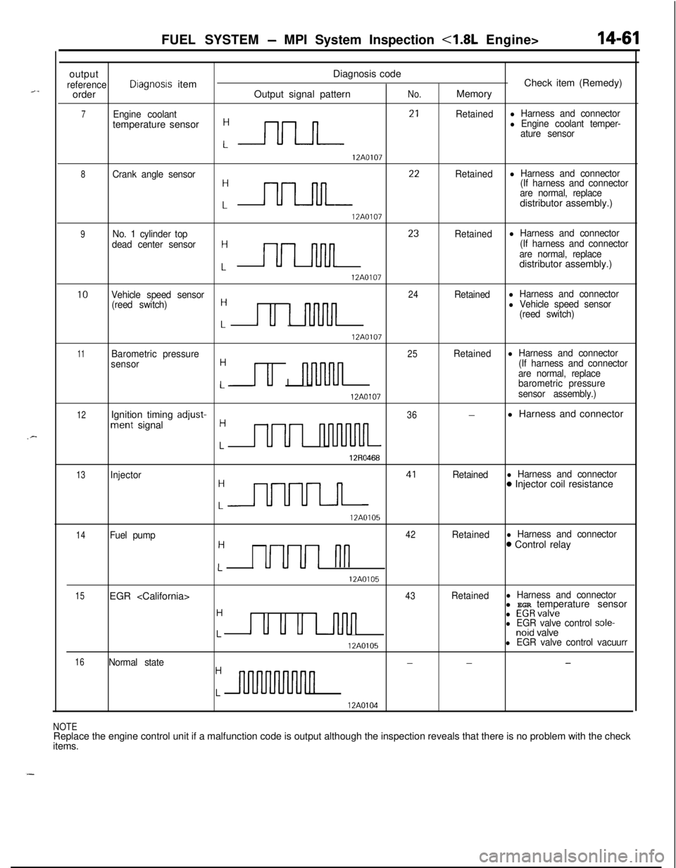
FUEL SYSTEM - MPI System Inspection <1.8L Engine>
outputDiagnosis code
referenceDiagnosis itemCheck item (Remedy)
orderOutput signal patternNo.Memory
7Engine coolantRetainedl Harness and connectortemperature sensor
:-rlrLn- 2’
l Engine coolant temper-
ature sensor
12A0107
8Crank angle sensor
:nn 22
Retainedl Harness and connector
(If harness and connector
are normal, replacedistributor assembly.)
12A0107
9No. 1 cylinder top
dead center sensorH
Lnn 23
Retainedl Harness and connector
(If harness and connector
are normal, replacedistributor assembly.)
12A0107
10Vehicle speed sensor24Retainedl Harness and connector
(reed switch)H
Lu 1 nnJln
l Vehicle speed sensor
(reed switch)
12A0107
11Barometric pressure25Retainedl Harness and connector
sensorH
u I nl-uvln
(If harness and connector
are normal, replace
Lbarometric pressure
12A0107sensor assembly.)
12Ignition timing adjust-36-l Harness and connectorment signalH
LUUI nluvuuL
12R0468
13Injector
:m 41
Retainedl Harness and connector0 Injector coil resistance
12A0105
14Fuel pump42Retainedl Harness and connectorH0 Control relay
LUUUI nn
12A0105
15EGR
H
u u u u-inn
l EGRvalvel EGR valve control sole-Lnoid valve
12A0105l EGR valve control vacuurr
16Normal state---H
Ln
12A0104
NOTEReplace the engine control unit if a malfunction code is output although the inspection reveals that there is no problem with the check
items.
Page 519 of 1216
FUEL SYSTEM - MPI Svstem InsDection <1.8L Engine>14-65
3FUO349
/--
’ 3FU03991
Idle speed controlservo connector(motor side, front view)
3FUO393
INHIBITOR SWITCHN14QRACsRefer to GROUP 21
- Service Adjustment Procedures.
POWER STEERING OIL PRESSURE SWITCH
N14flCJBRefer to GROUP 19 for power steering system inspection.
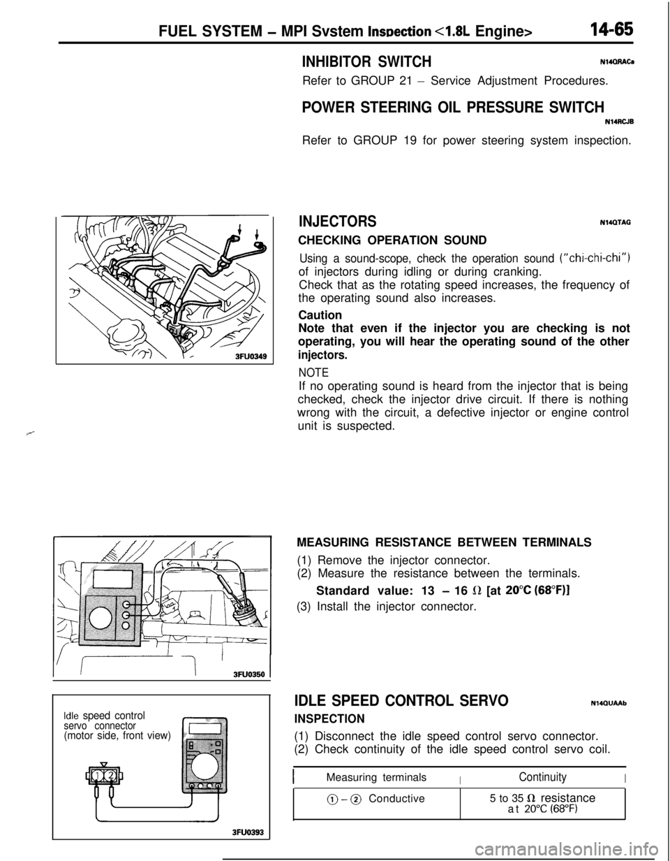
INJECTORSN14QTAGCHECKING OPERATION SOUND
Using a sound-scope, check the operation sound (“chi-chi-chi”)of injectors during idling or during cranking.
Check that as the rotating speed increases, the frequency of
the operating sound also increases.
Caution
Note that even if the injector you are checking is not
operating, you will hear the operating sound of the other
injectors.
NOTEIf no operating sound is heard from the injector that is being
checked, check the injector drive circuit. If there is nothing
wrong with the circuit, a defective injector or engine control
unit is suspected.
MEASURING RESISTANCE BETWEEN TERMINALS
(1) Remove the injector connector.
(2) Measure the resistance between the terminals.
Standard value: 13
- 16 L(Z [at 20°C (68”F)I(3) Install the injector connector.
IDLE SPEED CONTROL SERVO
INSPECTION
NlQQUAAb(1) Disconnect the idle speed control servo connector.
(2) Check continuity of the idle speed control servo coil.
IMeasuring terminalsIContinuityI
@ - @ Conductive5 to 35 fi resistance
at 20°C (68°F)
Page 523 of 1216
![MITSUBISHI ECLIPSE 1991 Service Manual FUEL SYSTEM - MPI System Inspection <2.0L DOHC Engine>
EGR control solenoid valve
[Calif. only]
Purge control solenoid valve
1
/AF--Y:rIgnition coil, Power transistor
Oxygen sensorPower
steering flu MITSUBISHI ECLIPSE 1991 Service Manual FUEL SYSTEM - MPI System Inspection <2.0L DOHC Engine>
EGR control solenoid valve
[Calif. only]
Purge control solenoid valve
1
/AF--Y:rIgnition coil, Power transistor
Oxygen sensorPower
steering flu](/img/19/57104/w960_57104-522.png)
FUEL SYSTEM - MPI System Inspection <2.0L DOHC Engine>
EGR control solenoid valve
[Calif. only]
Purge control solenoid valve
1
/AF--Y:rIgnition coil, Power transistor
Oxygen sensorPower
steering fluid Dressure switch
Coolant temDerature sensor
Page 525 of 1216

FUEL SYSTEM - MPI System Inspection <2.0L DOHC Engine>
InjectorII
01A0499
/
Purge control
Fuel pressureII solenoid valve
control valve
solenoid valve
0110503Ignition coil, Power transistor
IOxvnen sensorEGR control solenoid valve
[Calif. only]
Purge control solenoid valve
Fuel pressure control valve [Turbo only]
\’
\
16A0803Detonation sensor
\Power steering fluid oressure switch
Page 529 of 1216
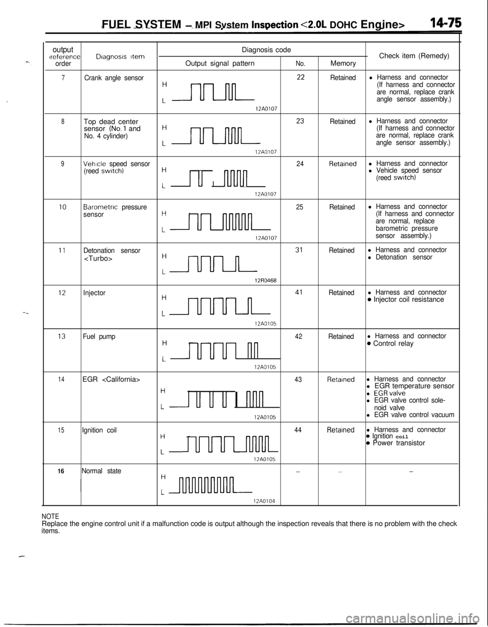
FUEL SYSTEM - MPI Svstem InsDection <2.0L DOHC Engine>
outputDiagnosis codeIreferenceDragnosrs ItemCheck item (Remedy)orderOutput signal patternNo.Memory
7Crank angle sensor
:nn **
Retainedl Harness and connector
(If harness and connector
are normal, replace crank
angle sensor assembly.)
12A0107
8Top dead center
:- 23
Retainedl Harness and connectorsensor (No.1 and(If harness and connector
No. 4 cylinder)are normal, replace crank
angle sensor assembly.)
12A0107
9Vehicle speed sensor24Retainedl Harness and connector
(reed swatch)H
I u I nlvln
l Vehicle speed sensor
(reed switch)
L12A0107
10Barometnc pressure25Retainedl Harness and connector
sensorH(If harness and connector
are normal, replace
LULllnMllbarometric pressure
12A0107sensor assembly.)
11Detonation sensorRetainedl Harness and connector
:m 31
l Detonation sensor
12R0468
12Injector
:m 41
Retainedl Harness and connector0 Injector coil resistance
12A0105
13Fuel pump42Retainedl Harness and connectorH
UUUI nn
0 Control relay
L12A0105
14EGR
Hl EGR temperature sensor
u u u I nnn
l EGRvalvel EGR valve control sole-Lnoid valve
12A0105l EGR valve control vacuum
15Ignition coil44Retainedl Harness and connectorH
UUUL-llMlL
0 Ignition coil0 Power transistor
L12A0105
16Normal state---H
L
12A0104
NOTEReplace the engine control unit if a malfunction code is output although the inspection reveals that there is no problem with the check
items.
Page 533 of 1216
FUEL SYSTEM - MPI System Inspection <2.0L QOHC Engine>14-79EGR TEMPERATURE SENSOR
N14RCHAaRefer to GROUP 25
- Exhaust Gas Recirculation System.
VEHICLE SPEED SENSOR
Refer to GROUP 8
- Meters and Gauges.
N140EBBaAIR CONDITIONER SWITCH
Nl4QQAEaRefer to GROUP 8
- Column Switch.
POWER STEERING OIL PRESSURE SWITCH
N14RCJBRefer to GROUP 19 for power steering system inspection.
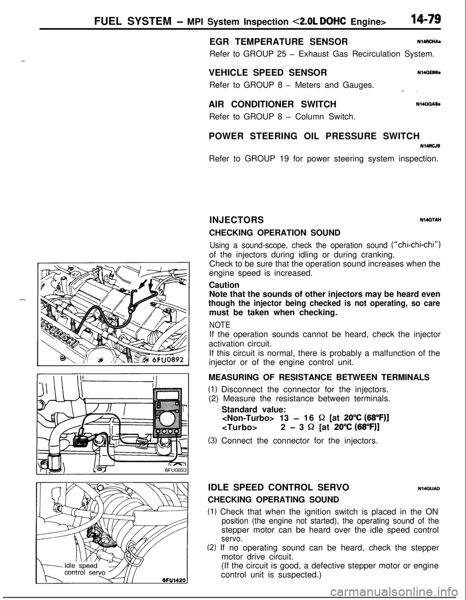
INJECTORS
NWXAHCHECKING OPERATION SOUND
Using a sound-scope, check the operation sound (“chi-chi-chi”)of the injectors during idling or during cranking.
Check to be sure that the operation sound increases when the
engine speed is increased.
Caution
Note that the sounds of other injectors may be heard even
though the injector being checked is not operating, so caremust be taken when checking.
NOTEIf the operation sounds cannot be heard, check the injector
activation circuit.
If this circuit is normal, there is probably a malfunction of the
injector or of the engine control unit.
MEASURING OF RESISTANCE BETWEEN TERMINALS
(1) Disconnect the connector for the injectors.
(2) Measure the resistance between terminals.
Standard value:
-16 S2 [at 20°C (68”F)]
- 3 52 [at 20% (68”F)]
(3) Connect the connector for the injectors.
IDLE SPEED CONTROL SERVO
N14QUADCHECKING OPERATING SOUND
(1) Check that when the ignition switch is placed in the ON
position (the engine not started), the operating sound of thestepper motor can be heard over the idle speed control
servo.
(2) If no operating sound can be heard, check the stepper
motor drive circuit.
(If the circuit is good, a defective stepper motor or engine
control unit is suspected.)
Page 536 of 1216
14-82FUEL SYSTEM - MPI System Inspection <2.0L DOHC Engine>
\ \\I \3FUO352
,\ \
\I \3FUO353
,\ ‘\R/
\ \\I \3FUo354
POWER TRANSISTORRefer to GROUP 8
- Ignition System
NlIAcQAl
a-4
AIR CONDITIONER POWER RELAYN14NCl.a -Refer to GROUP 24
- Air Conditioner.
PURGE CONTROL SOLENOID VALVEN14RCKARefer to GROUP 25
- Evaporative Emission Control System.
EGR CONTROL SOLENOID VALVE
N14NCURefer to GROUP 25
- Exhaust Gas Recirculation System.
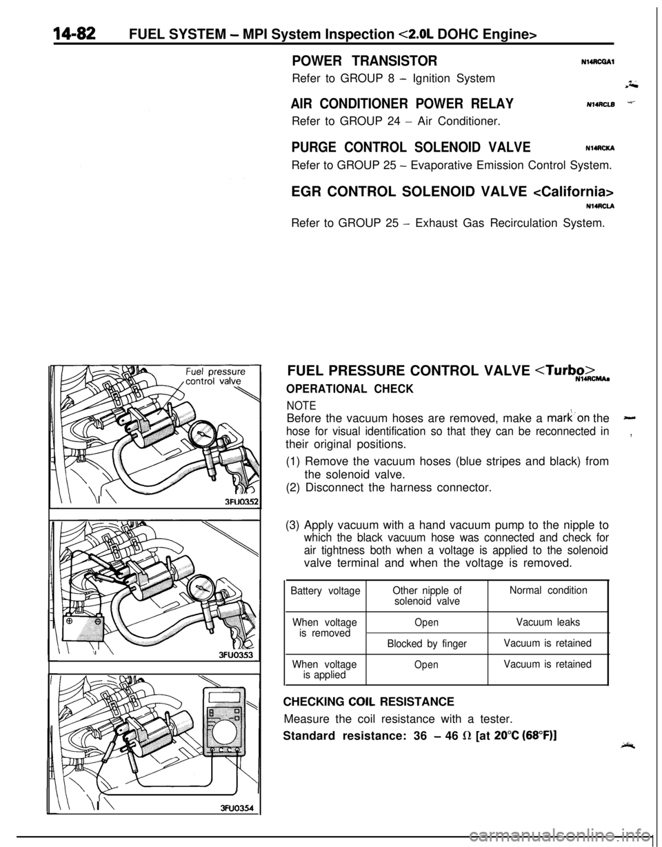
FUEL PRESSURE CONTROL VALVE
NOTEBefore the vacuum hoses are removed, make a mark’on the
-
hose for visual identification so that they can be reconnected in,their original positions.
(1) Remove the vacuum hoses (blue stripes and black) from
the solenoid valve.
(2) Disconnect the harness connector.
(3) Apply vacuum with a hand vacuum pump to the nipple to
which the black vacuum hose was connected and check for
air tightness both when a voltage is applied to the solenoidvalve terminal and when the voltage is removed.
Battery voltageOther nipple of
solenoid valveNormal condition
When voltage
is removed
When voltage
is applied
OpenVacuum leaks
Blocked by fingerVacuum is retained
OpenVacuum is retainedCHECKING
COIL RESISTANCE
Measure the coil resistance with a tester.
Standard resistance: 36
- 46 R [at 20°C (68”F)]
Page 538 of 1216
14-84FUEL SYSTEM - Injector
03*0095
Delivery pipe03A0095-SERVICE POINTS OF REMOVAL
H4s0m1‘~
3.DISCONNECTION OF THE HIGH PRESSURE FlJFL HOSE /;;
Bleed the residual pressure within the fuel pipe line’& as to~prevent the flow of fuel.
For information concerning the method to be folfowed for
bleeding the residual pressure, refer to
P.14-44.Caution
Cover the hose connection with rags to prevent splash,
of fuel that could be caused by some residual pressure
in the fuel pipe line.
12. REMOVAL OF DELIVERY PIPE/ 15. INJECTOR
Remove the deliver-y pipe (with the injectors attached to it).Caution
Care must be taken, when removing the delivery pipe,
not to drop the injector.
INSPEiZTION
INJECTORS
N14NGAA
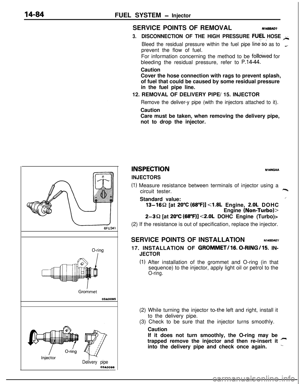
(1) Measure resistance between terminals of injector using a
circuit tester.+-%Standard value:
/13-1652 [at
20°C (68”F)] <1.8L Engine, 2.0L DOHC
Engine
(NoniTurbo)>
2-3Q [at 20°C (68”F)] <2.0L DOHC Engine (Turbo)>
(2) If the resistance is out of specification, replace the injector.
SERVICE POINTS OF INSTALLATION
N14SDAEl’17. INSTALLATION OF
GROMMET/lG. 0-RINGI15. IN-
JECTOR
(I) After installation of the grommet and O-ring (in that
sequence) to the injector, apply light oil or petrol to the
O-ring.(2) While turning the injector to.the left and right, install it
to the delivery pipe.
(3) Check to be sure that the injector turns smoothly.
Caution
If it does not turn smoothly, the O-ring may be
~trapped remove the injector and then re-insert it
into the delivery pipe and check once again.
L
Page 539 of 1216
FUEL SYSTEM - Injector/Throttle Body <1.8L Engine>14-85
Delivery pipe
Fuel pres
regulator
O-ringY pipe
O-kg
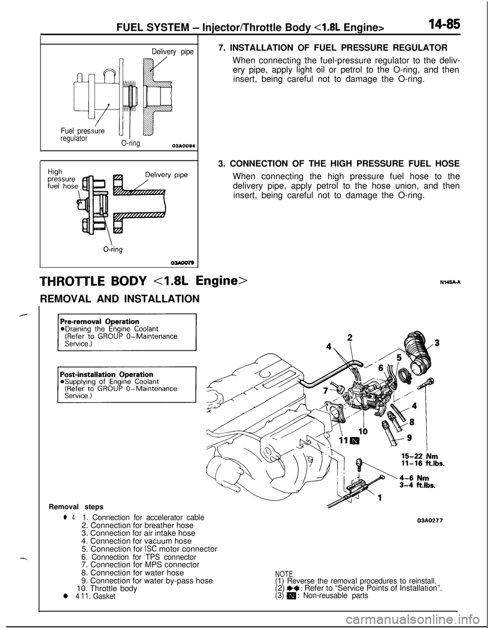
OWOO797. INSTALLATION OF FUEL PRESSURE REGULATOR
When connecting the fuel-pressure regulator to the deliv-
ery pipe, apply light oil or petrol to the O-ring, and then
insert, being careful not to damage the O-ring.
3. CONNECTION OF THE HIGH PRESSURE FUEL HOSE
When connecting the high pressure fuel hose to the
delivery pipe, apply petrol to the hose union, and then
insert, being careful not to damage the O-ring.
THROTTLE BODY 4.8L Engine>REMOVAL AND INSTALLATION
Removal steps
l 41. Connection for accelerator cable2. Connection for breather hose
3. Connection for air intake hose
4. Connection for vacuum hose
5. Connection for
ISC motor connector
6. Connection for TPS connector7. Connection for MPS connector
8. Connection for water hose
9. Connection for water by-pass hose
10. Throttle bodyl 4 11. Gasket
03AO277
NOTE(1) Reverse the removal procedures to reinstall.(2) I)+ : Refer to “Service Points of Installation”.(3) m : Non-reusable parts