boot MITSUBISHI ECLIPSE 1991 Owner's Manual
[x] Cancel search | Manufacturer: MITSUBISHI, Model Year: 1991, Model line: ECLIPSE, Model: MITSUBISHI ECLIPSE 1991Pages: 1216, PDF Size: 67.42 MB
Page 116 of 1216
3-‘14REAR AXLE - Drive Shaft
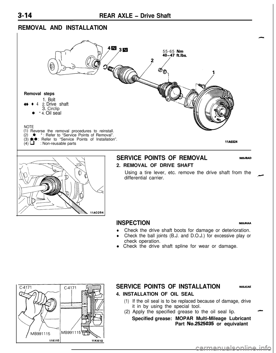
REMOVAL AND INSTALLATION55-65
N.m40-47 ft.lbs.
Removal steps
1. Bolt+e l 42. Drive shaft3. Circlip
l * 4. Oil seal
NOTE(1) Reverse the removal procedures to reinstall.(2) l * : Refer to “Service Points of Removal”.<-,(3) ii : Refer to “Service Points of Installation”.
(4) q : Non-reusable partsllA0324
SERVICE POINTS OF REMOVALNO3JEAD2. REMOVAL OF DRIVE SHAFT
Using a tire lever, etc. remove the drive shaft from the
differential carrier.
INSPECTIONNOJJHAA
lCheck the drive shaft boots for damage or deterioration.
lCheck the ball joints (B.J. and D.O.J.) for excessive play orcheck operation.
l Check the drive shaft spline for wear or damage.
SERVICE POINTS OF INSTALLATIONN03JCAE4. INSTALLATION OF OIL SEAL
(1)If the oil seal is to be replaced because of damage, driveit in by using the special tool.
(2) Apply the specified grease to the oil seal lip.
Specified grease:MOPAR Multi-Mileage Lubricant
Part No.2525035 or equivalant
,-
-
llK110llK610
Page 117 of 1216
REAR AXLE - Drive Shaft
Boot band
CTwo-part serration
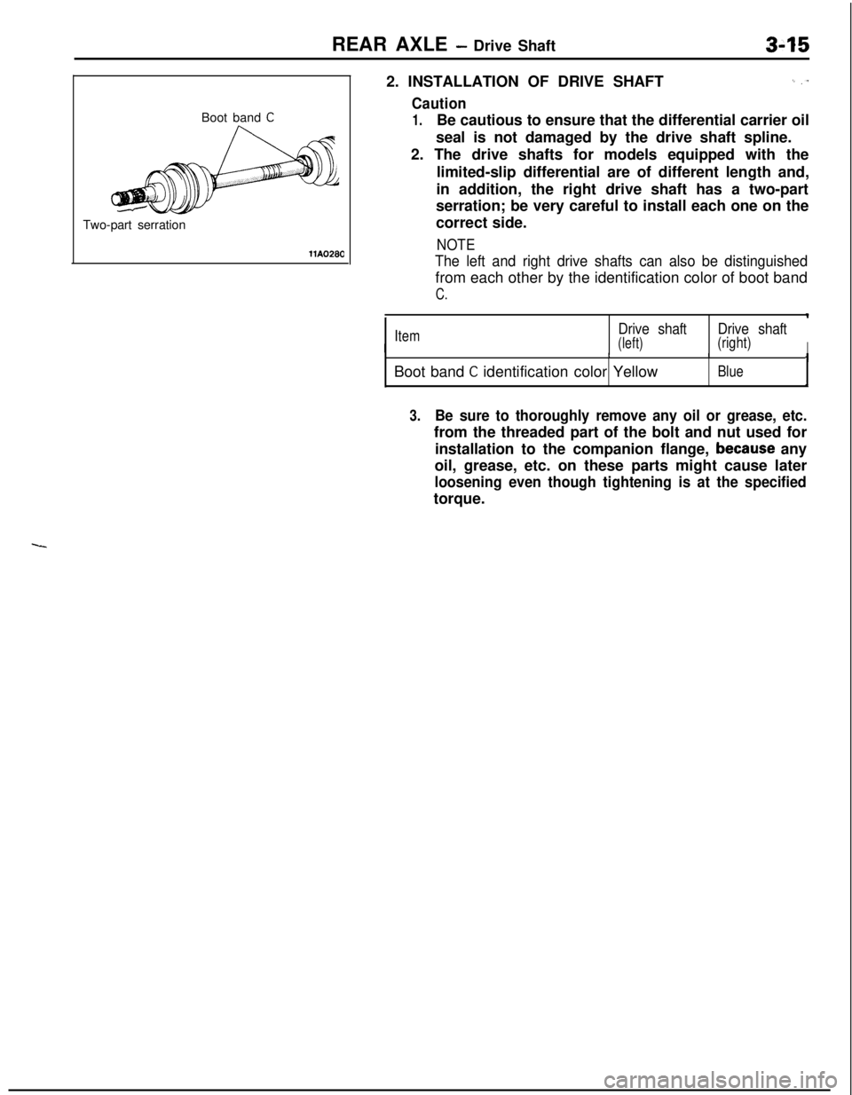
llA02802. INSTALLATION OF DRIVE SHAFT
I_ ,T
Caution
1.Be cautious to ensure that the differential carrier oil
seal is not damaged by the drive shaft spline.
2. The drive shafts for models equipped with the
limited-slip differential are of different length and,
in addition, the right drive shaft has a two-part
serration; be very careful to install each one on the
correct side.
NOTE
The left and right drive shafts can also be distinguishedfrom each other by the identification color of boot band
C.
IItemDrive shaftDrive shaft
(left)(right)IIIBoot band
C identification color YellowBlueI
3.Be sure to thoroughly remove any oil or grease, etc.from the threaded part of the bolt and nut used for
installation to the companion flange,
because any
oil, grease, etc. on these parts might cause later
loosening even though tightening is at the specifiedtorque.
Page 118 of 1216
3-16REAR AXLE - Drive Shaft
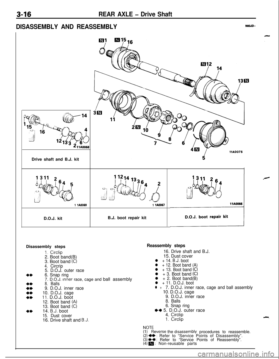
DISASSEMBLY AND REASSEMBLY
N03JD--Drive shaft and B.J. kit
1 lA6969D.O.J. kitB.J. boot repair kit1 lAO967Disassembly steps
I. Circlip2. Boot band(B)
3. Boot band
(C)4.Circrip
5. D.O.J. outer race
6. Snap ring7. D.O.J. Inner race, cage and ball assembly
8.Balls9. D.O.J. inner race
10. D.O.J. cage
11, D.O.J. boot
12. Boot band (A)13. Boot band (C)14. B.J. boot
15.Dust cover16. Drive shaft and B.J.
Reassembly steps
16. Drive shaft and B.J.15. Dust cover
l + 14. B.J. boot
l + 12. Boot band (A)
l + 13. Boot band (C)l + 3. Boot band (Cll + 2. Boot band(B)l + 11. D.O.J. bootl +7. D.O.J. inner race, cage and ball assembly10. D.O.J. cage9. D.O.J. inner race
8. Balls
6. Snap ring
I)+ 5. D.O.J. outer race
4. CirclipI. Circlip
!ygeverse the disassembly procedures to reassemble.(2) +* : Refer to “Service Points of Disassembly”.(3) I)+ : Refer to “Service Points of Reassembly”.(4) m : Non-reusable parts
Page 119 of 1216
REAR AXLE - Drive Shaft3-1711
ES07
.-
llYO97
8.J: bootBoot bands
D.O.J. bootllW592
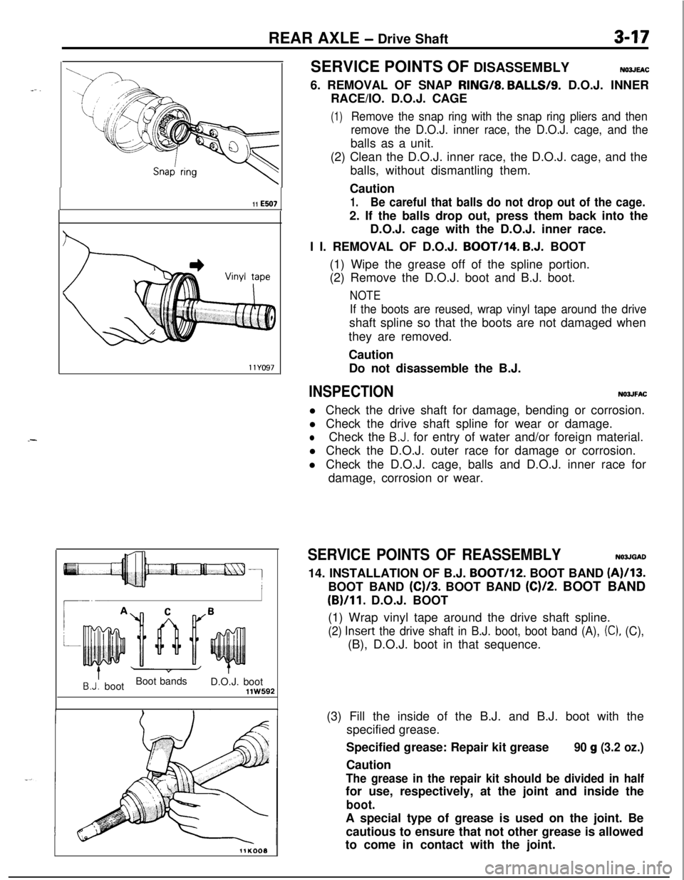
11KOOOSERVICE POINTS OF DISASSEMBLY
NO3JEAC6. REMOVAL OF SNAP RING/8.
BALLS/S. D.O.J. INNER
RACE/IO. D.O.J. CAGE
(1)Remove the snap ring with the snap ring pliers and then
remove the D.O.J. inner race, the D.O.J. cage, and theballs as a unit.
(2) Clean the D.O.J. inner race, the D.O.J. cage, and the
balls, without dismantling them.
Caution
1.Be careful that balls do not drop out of the cage.2. If the balls drop out, press them back into the
D.O.J. cage with the D.O.J. inner race.
I I. REMOVAL OF D.O.J.
BOOT/I4. B.J. BOOT
(1) Wipe the grease off of the spline portion.
(2) Remove the D.O.J. boot and B.J. boot.
NOTE
If the boots are reused, wrap vinyl tape around the driveshaft spline so that the boots are not damaged when
they are removed.
Caution
Do not disassemble the B.J.
INSPECTIONNOJJFACl Check the drive shaft for damage, bending or corrosion.
l Check the drive shaft spline for wear or damage.
lCheck the B.J. for entry of water and/or foreign material.
l Check the D.O.J. outer race for damage or corrosion.
l Check the D.O.J. cage, balls and D.O.J. inner race for
damage, corrosion or wear.
SERVICE POINTS OF REASSEMBLYN03JGAD14. INSTALLATION OF B.J.
BOOT/I*. BOOT BAND (A)/I3.BOOT BAND
(C)/3. BOOT BAND (C)/2. BOOT BAND
(B)/II. D.O.J. BOOT
(1) Wrap vinyl tape around the drive shaft spline.
(2) Insert the drive shaft in B.J. boot, boot band (A), (C), (C),(B), D.O.J. boot in that sequence.
(3) Fill the inside of the B.J. and B.J. boot with the
specified grease.
Specified grease: Repair kit grease
Caution
90 g (3.2 oz.)
The grease in the repair kit should be divided in halffor use, respectively, at the joint and inside the
boot.A special type of grease is used on the joint. Be
cautious to ensure that not other grease is allowed
to come in contact with the joint.
Page 120 of 1216
3-18REAR AXLE - Drive Shaft
ring
\
Inner race
1180116
llE507
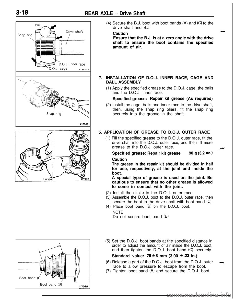
7.(4) Secure the B.J. boot with boot bands (A) and
(C) to the
drive shaft and B.J.
Caution
-Ensure that the B.J. is at a zero angle with the drive
shaft to ensure the boot contains the specified
amount of air.
INSTALLATION OF D.O.J. INNER RACE, CAGE AND
BALL ASSEMBLY
(1) Apply the specified grease to the D.O.J. cage, the balls
and the D.O.J. inner race.
Specified grease:Repair kit grease (As required)
(2) Install the cage, balls and inner race to the drive shaft,
then, using the snap ring pliers, fit the snap ring
securely into the groove in the shaft.
5. APPLICATION OF GREASE TO D.O.J. OUTER RACE
(1) Fill the specified grease to the D.O.J. outer race, fit the
drive shaft into the D.O.J. outer race, and then fill moregrease to the D.O.J. outer race.
Specified grease: Repair kit grease
90 g (3.2 oz.)
Caution
The grease in the repair kit should be divided in halffor use, respectively, at the joint and inside the
boot.A special type of grease is used on the joint. Be
cautious to ensure that no other grease is allowed
to come in contact with the joint.
(2) Install the
circlip to the D.O.J. outer race.
(3) Assemble the D.O.J. boot to the D.O.J. outer race, thensecure the boot to the drive shaft with boot band
(C).(4) Place boot band
(B) on the D.O.J. boot.
NOTEDo not secure boot band
(9)(5) Set the D.O.J. boot bands at the specified distance in
order to adjust the amount of air inside the D.O.J. boot,and then tighten the D.O.J. boot band
(C) securely.
Standard value: 76+-3 mm (3.00
& .23 in.)
(6) Release a part of the D.O.J. boot from the D.O.J. outer
--race to allow pressure to escape from the boot.
(7) Tighten boot band
(9) and secure the D.O.J. boot.
Boot band
(8’)
Page 146 of 1216
5-6BRAKES - Specifications/Special Tools
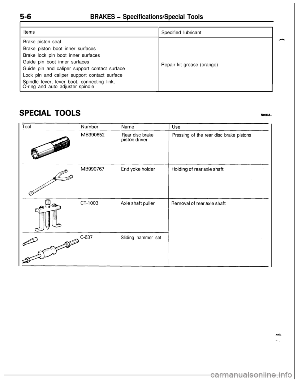
ItemsBrake piston seal
Brake piston boot inner surfaces
Brake lock pin boot inner surfaces
Guide pin boot inner surfaces
Guide pin and caliper support contact surface
Lock pin and caliper support contact surface
Spindle lever, lever boot, connecting link,
O-ring and auto adjuster spindle
SPECIAL TOOLSSpecified lubricant
Repair kit grease (orange)
Rear disc brake
Pressing of the rear disc brake pistons
Sliding hammer set
Page 187 of 1216
BRAKES - Service Adjustment Procedures5-47
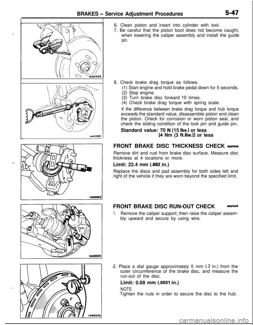
14AO399-6. Clean piston and insert into cylinder with tool.
7. Be careful that the piston boot does not become caught,
when lowering the caliper assembly and install the guide
pin.8. Check brake drag torque as follows.
(1) Start engine and hold brake pedal down for 5 seconds.
(2) Stop engine.
(3) Turn brake disc forward
10 times.
(4) Check brake drag torque with spring scale.
If the difference between brake drag torque and hub torqueexceeds the standard value, disassemble piston and clean
the piston. Check for corrosion or worn piston seal, and
check the sliding condition of the lock pin and guide pin.
Standard value: 70
N (15 Ibs.) or less
[4 Nm (3 ftlbs.)] or less
FRONT BRAKE DISC THICKNESS CHECK
NQ5FRASRemove dirt and rust from brake disc surface. Measure disc
thickness at 4 locations or more.
Limit: 22.4 mm
(.882 in.)
Replace the discs and pad assembly for both sides left and
right of the vehicle if they are worn beyond the specified limit.
FRONT BRAKE DISC RUN-OUT CHECKNOIFSAB
1.Remove the caliper support; then raise the caliper assem-
bly upward and secure by using wire.
2. Place a dial gauge approximately 5 mm
(2 in.) from the
outer circumference of the brake disc, and measure the
run-out of the disc.
Limit: 0.08 mm
(.0031 in.)
NOTETighten the nuts in order to secure the disc to the hub.
Page 189 of 1216
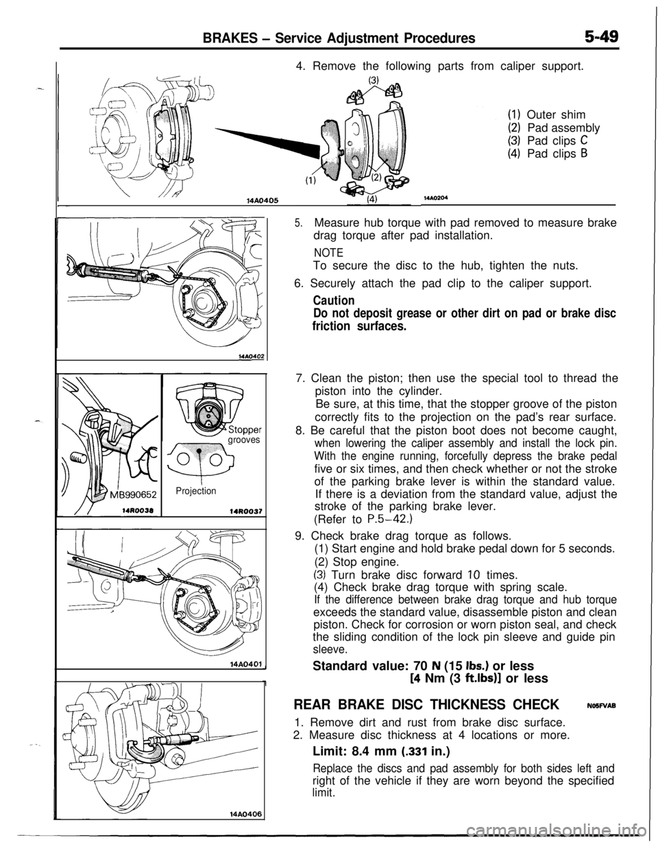
BRAKES - Service Adjustment Procedures5-494. Remove the following parts from caliper support.
14AO405
14AOs
grooves
Q
0 0
Projection
14R0037
14A0401
14AO406
MAO204Outer shim
Pad assembly
Pad clips
CPad clips
B
5.Measure hub torque with pad removed to measure brake
drag torque after pad installation.
NOTETo secure the disc to the hub, tighten the nuts.
6. Securely attach the pad clip to the caliper support.
Caution
Do not deposit grease or other dirt on pad or brake disc
friction surfaces.7. Clean the piston; then use the special tool to thread the
piston into the cylinder.
Be sure, at this time, that the stopper groove of the piston
correctly fits to the projection on the pad’s rear surface.
8. Be careful that the piston boot does not become caught,
when lowering the caliper assembly and install the lock pin.
With the engine running, forcefully depress the brake pedalfive or six times, and then check whether or not the stroke
of the parking brake lever is within the standard value.
If there is a deviation from the standard value, adjust the
stroke of the parking brake lever.
(Refer to
P.5-42.)9. Check brake drag torque as follows.
(1) Start engine and hold brake pedal down for 5 seconds.
(2) Stop engine.
(3) Turn brake disc forward 10 times.
(4) Check brake drag torque with spring scale.
If the difference between brake drag torque and hub torqueexceeds the standard value, disassemble piston and clean
piston. Check for corrosion or worn piston seal, and check
the sliding condition of the lock pin sleeve and guide pin
sleeve.Standard value: 70
N (15 Ibs.) or less
[4 Nm (3 ft.lbs)] or less
REAR BRAKE DISC THICKNESS CHECKNOSWAB
1. Remove dirt and rust from brake disc surface.
2. Measure disc thickness at 4 locations or more.
Limit: 8.4 mm
(.331 in.)
Replace the discs and pad assembly for both sides left andright of the vehicle if they are worn beyond the specified
limit.
Page 207 of 1216
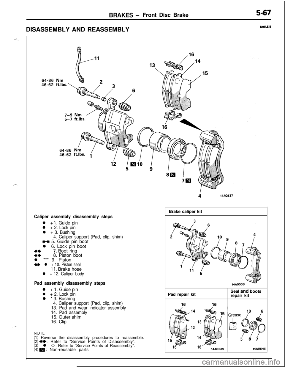
BRAKES -Front Disc Brake5-67DISASSEMBLY AND REASSEMBLY
64-86
46-62
64-86
46-62
ft.lbs. ;
Caliper assembly disassembly steps
l + 1. Guide pin
l + 2. Lock pin
l + 3. Bushing
4. Caliper support (Pad, clip, shim)
e+ 5. Guide pin boot
l 6. Lock pin boot
::7. Boot ring
8. Piston boot
l *** 9. Piston
4I) l + 10. Piston sealIl. Brake hosel + 12. Caliper body
Pad assembly disassembly steps
l + 1. Guide pin
l + 2. Lock pinl * 3. Bushing
4. Caliper support (Pad, clip, shim)
13. Pad and wear indicator assembly
14. Pad assembly15. Outer shim
16. Clip
NOSLE-B
.16
(1) Reverse the disassembly procedures to reassemble.(2) +e : Refer to “Service Points of Disassembly”.(3) l O : Refer to “Service Points of Reassembly”.(4) m : Non-reusable partsBrake caliper kit
3Pad repair kitSeal and boots
repair kit
14
106
13
13
1614
1614AO539
514A054(3
Page 208 of 1216
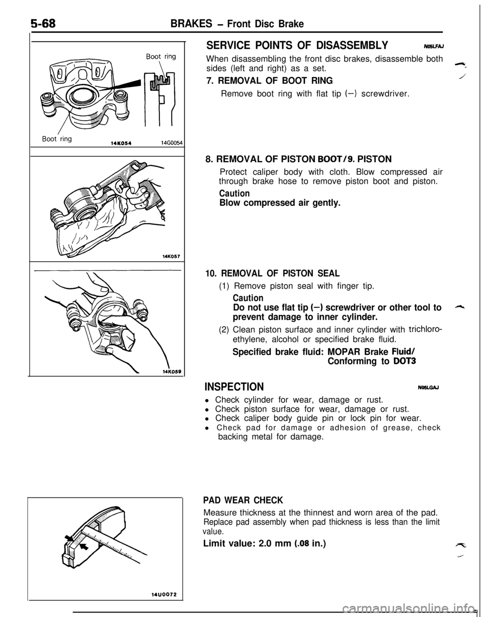
5-68BRAKES - Front Disc Brake
14KO5414GOO54
14K057
14UOO72
SERVICE POINTS OF DISASSEMBLYNO5LFAJWhen disassembling the front disc brakes, disassemble both
sides (left and right) as a set.
7. REMOVAL OF BOOT RINGRemove boot ring with flat tip
(-) screwdriver.
8. REMOVAL OF PISTON
BOOT/g. PISTON
Protect caliper body with cloth. Blow compressed air
through brake hose to remove piston boot and piston.
Caution
Blow compressed air gently.
10. REMOVAL OF PISTON SEAL(1) Remove piston seal with finger tip.
Caution
Do not use flat tip (-) screwdriver or other tool to
prevent damage to inner cylinder.(2) Clean piston surface and inner cylinder with
trichloro-ethylene, alcohol or specified brake fluid.
Specified brake fluid: MOPAR Brake Fluid/
Conforming to DOT3
INSPECTIONNOSLGAJl Check cylinder for wear, damage or rust.
l Check piston surface for wear, damage or rust.
l Check caliper body guide pin or lock pin for wear.
l Check pad for damage or adhesion of grease, check
backing metal for damage.
PAD WEAR CHECKMeasure thickness at the thinnest and worn area of the pad.
Replace pad assembly when pad thickness is less than the limit
value.Limit value: 2.0 mm
(.08 in.)