boot MITSUBISHI ECLIPSE 1991 User Guide
[x] Cancel search | Manufacturer: MITSUBISHI, Model Year: 1991, Model line: ECLIPSE, Model: MITSUBISHI ECLIPSE 1991Pages: 1216, PDF Size: 67.42 MB
Page 68 of 1216
FRONT SUSPENSION - Drive Shaft
IllA0127
llE560
Grease
llE563
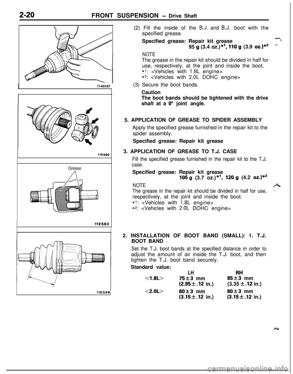
llE559(2) Fill the inside of the
B.J. and B.J., boot with the
specified grease.
Specified grease: Repair kit grease
Wil95
g (3.4 oz.)*I, 110 g (3.9 oz.)**-
NOTEThe grease in the repair kit should be divided in half for
use, respectively, at the joint and inside the boot.
*I:
*2:
(3) Secure the boot bands.
Caution
The boot bands should be tightened with the drive
shaft at a
0” joint angle.
5. APPLICATION OF GREASE TO SPIDER ASSEMBLY
Apply the specified grease furnished in the repair kit to the
spider assembly.
Specified grease: Repair kit grease
3. APPLICATION OF GREASE TO T.J. CASE
Fill the specified grease furnished in the repair kit to the T.J.
case.Specified grease: Repair kit grease
105 g (3.7 oz.)*‘I,120 g (4.2 oz.)**
NOTEA
The grease in the repair kit should be divided in half for use,-respectively, at the joint and inside the boot.
*I:
*2:
2. INSTALLATION OF BOOT BAND (SMALL)/ 1. T.J.
BOOT BAND
Set the T.J. boot bands at the specified distance in order toadjust the amount of air inside the T.J. boot, and then
tighten the T.J. boot band securely.
Standard value:
LHRH
(2.95f .I2 in.)(3.35 f .I2 in.)
<2.0L>80f3 mmSO+3 mm
(3.15f.12 in.)(3.15+ .I2 in.)
Page 69 of 1216
FRONT SUSPENSION - Drive Shaft
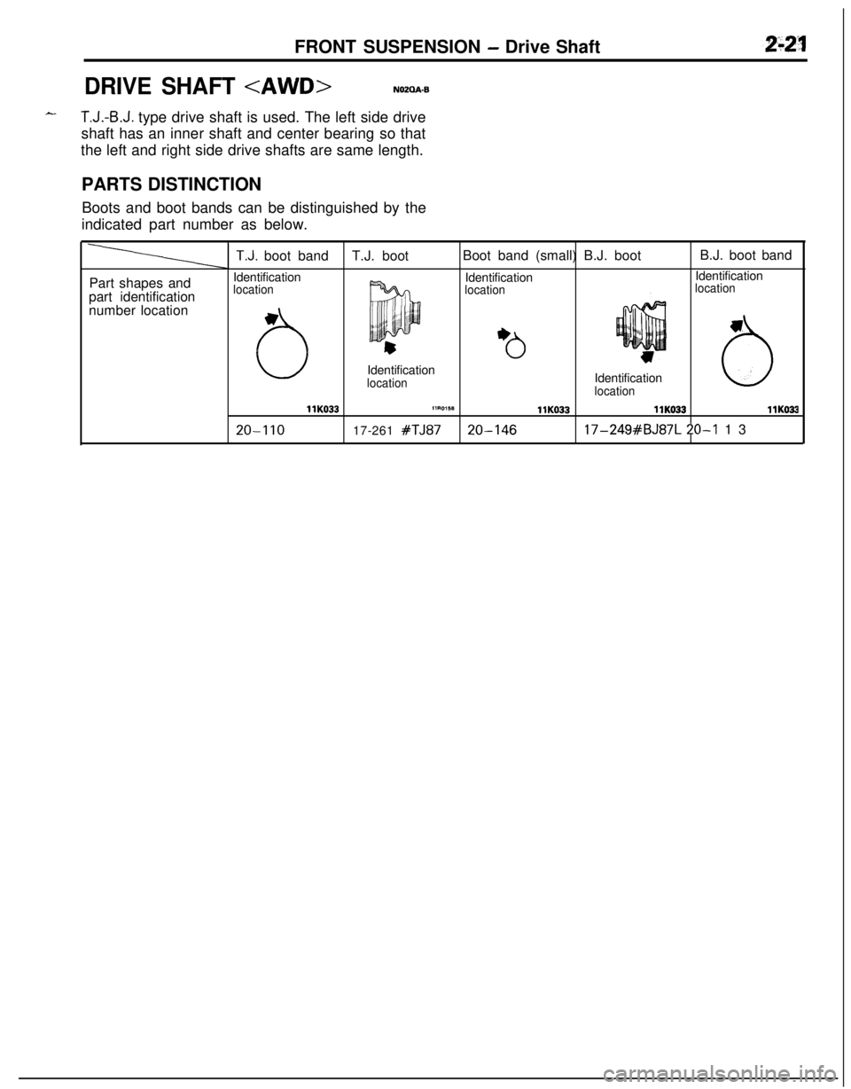
DRIVE SHAFT
T.J.-B.J. type drive shaft is used. The left side drive
shaft has an inner shaft and center bearing so that
the left and right side drive shafts are same length.
PARTS DISTINCTION
Boots and boot bands can be distinguished by the
indicated part number as below.
Part shapes and
part identification
number location
T.J. boot bandT.J. bootBoot band (small) B.J. bootB.J. boot band
Identification
IdentificationIdentification
location
locationlocation
uIdentification
locationIdentificationlocation6
llK033llRO,SBllK033llK033llKO33
20-I 1017-261 #TJ8720-14617-249#BJ87L 20-I 13
Page 71 of 1216
FRONT SUSPENSION - Drive Shaft2-23
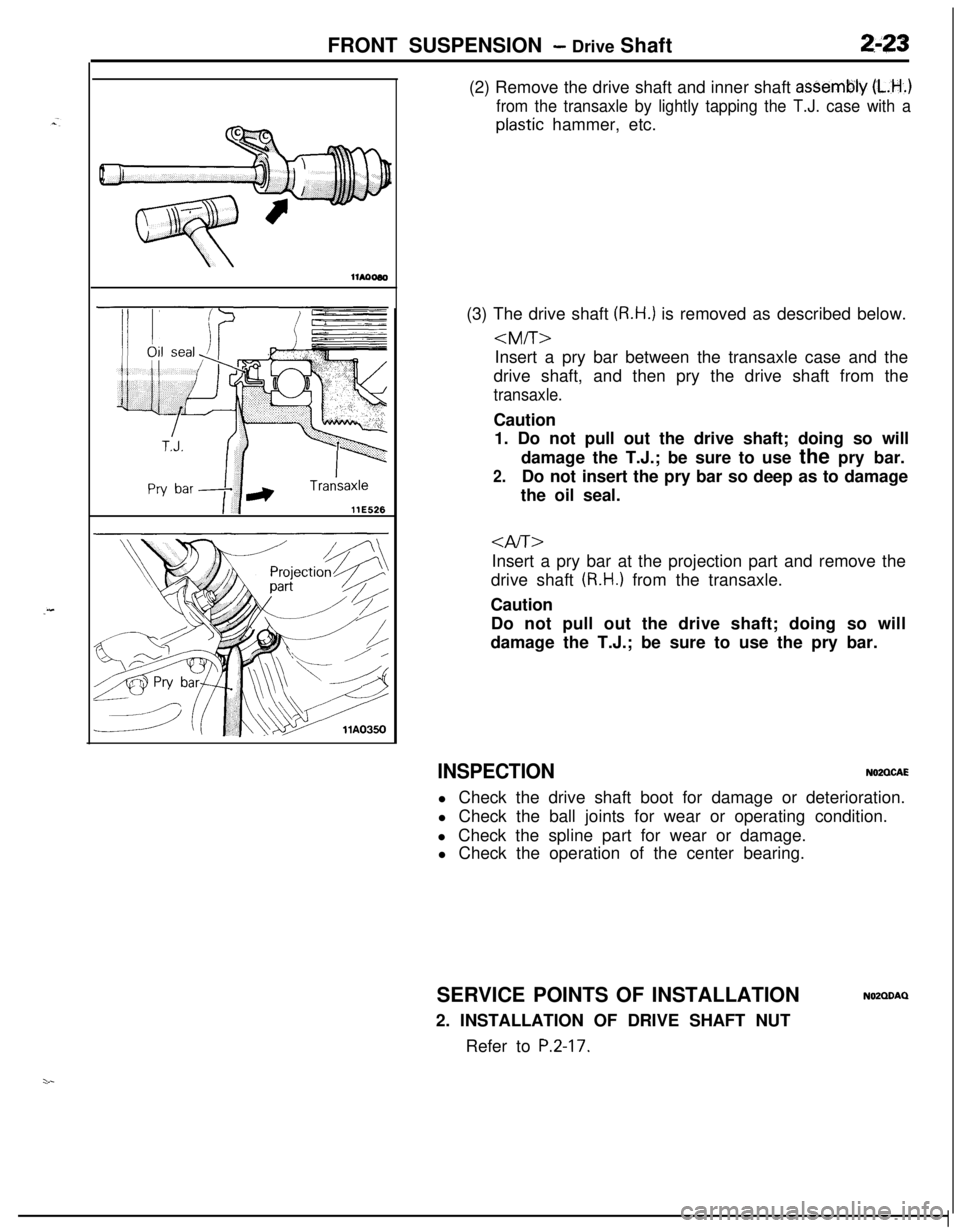
llE526(2) Remove the drive shaft and inner shaft
asSembly (L.H..)
from the transaxle by lightly tapping the T.J. case with a
plastic hammer, etc.
(3) The drive shaft
(R.H.) is removed as described below.
drive shaft, and then pry the drive shaft from the
transaxle.Caution
1. Do not pull out the drive shaft; doing so will
damage the T.J.; be sure to use the pry bar.
2.Do not insert the pry bar so deep as to damage
the oil seal.
Insert a pry bar at the projection part and remove the
drive shaft
(R.H.) from the transaxle.
Caution
Do not pull out the drive shaft; doing so will
damage the T.J.; be sure to use the pry bar.
INSPECTIONN02QCAEl Check the drive shaft boot for damage or deterioration.
l Check the ball joints for wear or operating condition.
l Check the spline part for wear or damage.
l Check the operation of the center bearing.
SERVICE POINTS OF INSTALLATION
2. INSTALLATION OF DRIVE SHAFT NUT
Refer to
P.2-17.
NOZQDAQ
Page 72 of 1216
2-24FRONT SUSPENSION - Drive Shaft
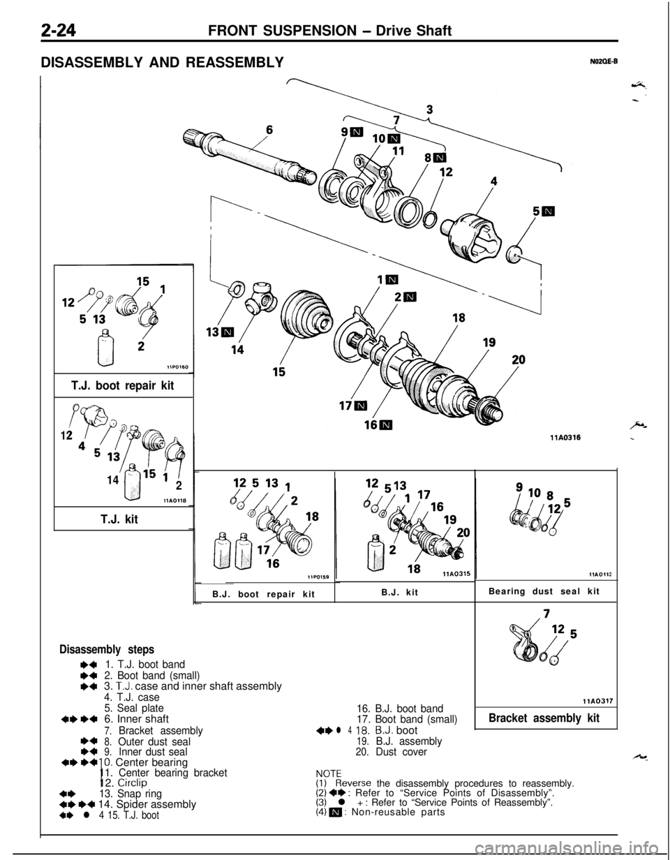
DISASSEMBLY AND REASSEMBLY
NOZQE-B
T.J. boot repair kit
d-
‘Pr12
45,3 ;c
!'F?
14- 151
0
92
11AOH8
T.J. kit
llA0316B.J. boot repair kitB.J. kit
Disassembly steps
1. T.J. boot band
2. Boot band (small)3.
T.J. case and inner shaft assembly
4. T.J. case
5. Seal plate6. Inner shaft
16. B.J. boot band
17. Boot band (small)
7.Bracket assembly+I)l 418.B.J. boot
8.Outer dust seal19.B.J. assembly9.Inner dust seal20.Dust coverBearing dust seal kit
llA0317
Bracket assembly kit
10. Center bearing11. Center bearing bracket12. Circlip
4*13. Snap ring+e e+ 14. Spider assembly4I) l 4 15. T.J. boot
FJ)TEeverse the disassembly procedures to reassembly.(2) +e : Refer to “Service Points of Disassembly”.(3) l + : Refer to “Service Points of Reassembly”.(4) m : Non-reusable parts
Page 73 of 1216

FRONT SUSPENSION - Drive Shaft2-25
T.J. caseI
\ \It/P-
IllA0092
-/ MB990938
11E561llYO97SERVICE POINTS OF DISASSEMBLY
NOZOFED6. REMOVAL OF INNER
SHAFT(1) Using the special tool, remove the inner shaft assem-
bly, together with the seal plate, from the T.J. case.
from
(2) Use the suitable puller to remove the inner shaft
the center bearing bracket.
10. REMOVAL OF CENTER BEARING
Use the special tools to remove the center bearing from thecenter bearing bracket.
ix13. REMOVAL OF SNAP
RING/l4. SPIDER ASSEMBLY
(1) Remove the snap ring from the drive shaft with the
snap ring pliers.
(2) Take out the spider assembly from the drive shaft.
(3) Clean the spider assembly.
Caution
1. Do not disassemble the spider assembly.
2.If the T.J. of the drive shaft assembly is bent, thejoint may be damaged. Use care in handling the
drive shaft.
3. The drive shaft joint use special grease. Do not
add another type of grease.
15. REMOVAL OF T.J.
BOOT/l8. B.J. BOOT
(1) Wrap vinyl tape around the spline part on the T.J. side
of the drive shaft so that the T.J. and B.J. boots are notdamaged when they are removed.
(2) Withdraw the T.J. and
B.J. boots from the drive shaft.
Caution
Do not disassemble the B.J.
Distinguish between B.J. boot and T.J. boot parts.
Page 74 of 1216
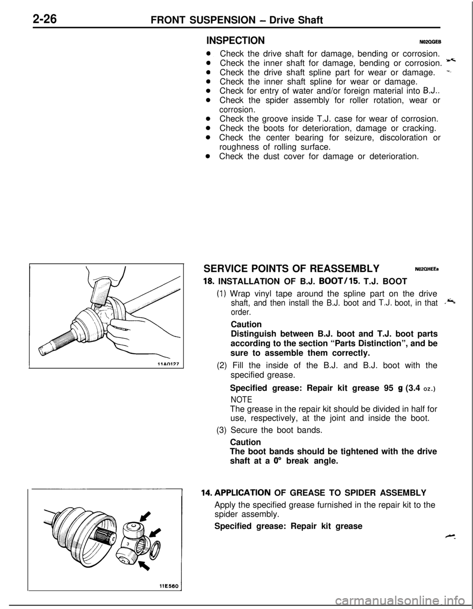
2-26FRONT SUSPENSION - Drive Shaft
llE560
INSPECTIONN02QGEB
0
0
0
0Check the dust cover for damage or deterioration.Check the drive shaft for damage, bending or corrosion.
Check the inner shaft for damage, bending or corrosion.
-Check the drive shaft spline part for wear or damage.
=-Check the inner shaft spline for wear or damage.
Check for entry of water and/or foreign material into
B-J..Check the spider assembly for roller rotation, wear or
corrosion.Check the groove inside T.J. case for wear of corrosion.
Check the boots for deterioration, damage or cracking.
Check the center bearing for seizure, discoloration or
roughness of rolling surface.
SERVICE POINTS OF REASSEMBLY
NOZQHEEa
18, INSTALLATION OF B.J. BOOT/15. T.J. BOOT
(1) Wrap vinyl tape around the spline part on the drive
shaft, and then install the B.J. boot and T.J. boot, in that.*
order.Caution
Distinguish between B.J. boot and T.J. boot parts
according to the section “Parts Distinction”, and be
sure to assemble them correctly.
(2) Fill the inside of the B.J. and B.J. boot with the
specified grease.
Specified grease: Repair kit grease 95
g (3.4 OZ.)
NOTEThe grease in the repair kit should be divided in half for
use, respectively, at the joint and inside the boot.
(3) Secure the boot bands.
Caution
The boot bands should be tightened with the drive
shaft at a
0” break angle.14.APPLlCATlON OF GREASE TO SPIDER ASSEMBLY
Apply the specified grease furnished in the repair kit to the
spider assembly.
Specified grease: Repair kit grease
Page 76 of 1216
2-28FRONT SUSPENSION - Drive Shaft
Inner shaft
llA0083
1T.J. case.,
MB9909383%QilD998801
r
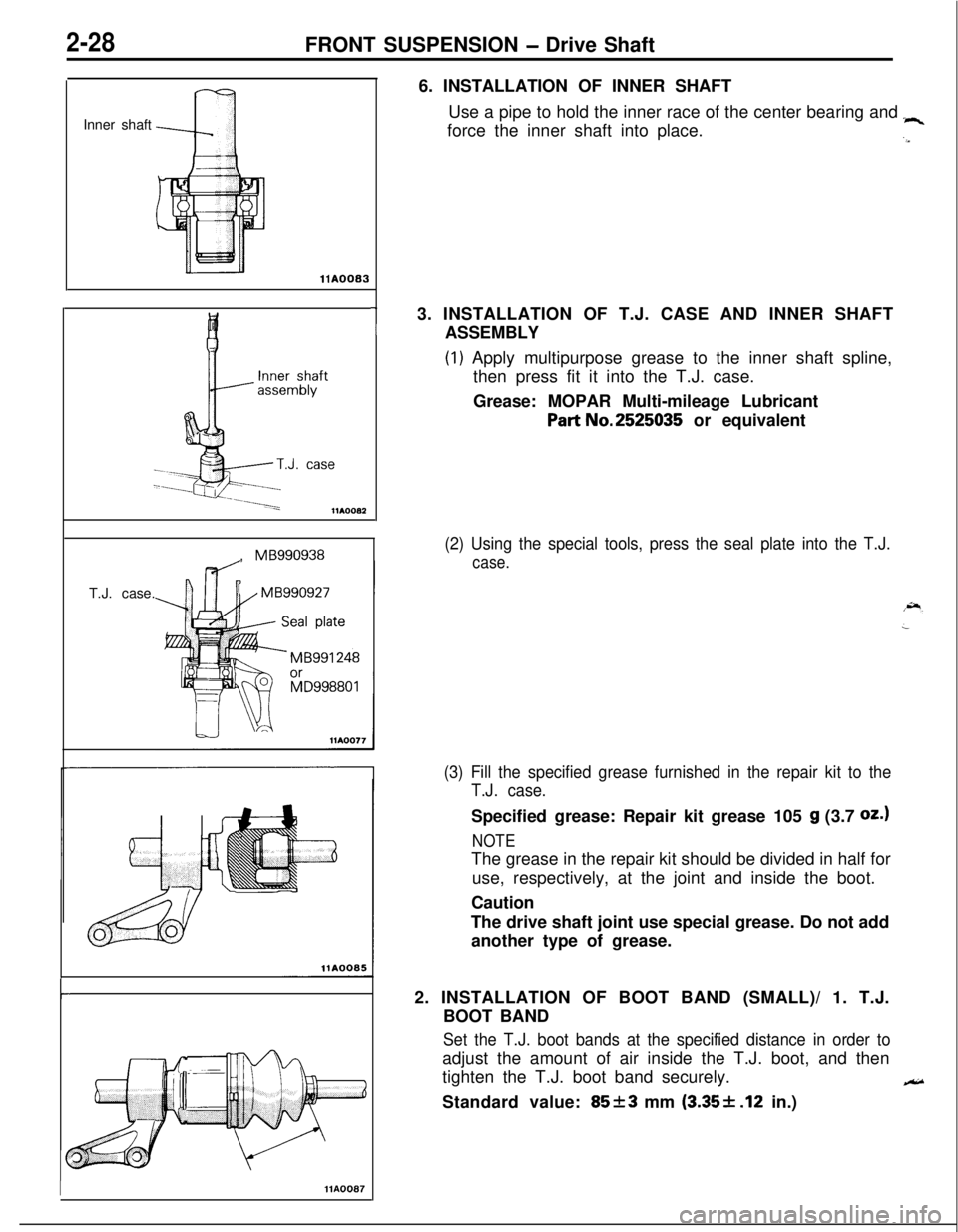
IHA00876. INSTALLATION OF INNER SHAFT
Use a pipe to hold the inner race of the center bearing and
“4force the inner shaft into place.
.a3. INSTALLATION OF T.J. CASE AND INNER SHAFT
ASSEMBLY
(1) Apply multipurpose grease to the inner shaft spline,
then press fit it into the T.J. case.
Grease: MOPAR Multi-mileage Lubricant
Part No.2525035 or equivalent
(2) Using the special tools, press the seal plate into the T.J.
case.
(3) Fill the specified grease furnished in the repair kit to the
T.J. case.Specified grease: Repair kit grease 105
g (3.7 oz.1
NOTEThe grease in the repair kit should be divided in half for
use, respectively, at the joint and inside the boot.
Caution
The drive shaft joint use special grease. Do not add
another type of grease.
2. INSTALLATION OF BOOT BAND (SMALL)/ 1. T.J.
BOOT BAND
Set the T.J. boot bands at the specified distance in order toadjust the amount of air inside the T.J. boot, and then
tighten the T.J. boot band securely.
eStandard value:
85f3 mm (3.35+ .12 in.)
Page 104 of 1216
3-2REAR AXLE - Specifications
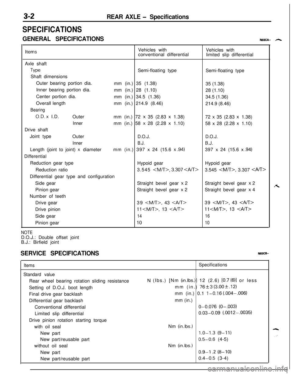
SPECIFICATIONS
GENERAL SPECIFICATIONSNO3CA- h
ItemsVehicles with
Vehicles with
conventional differential
limited slip differential
Axle shaft
TypeSemi-floating type
Semi-floating type
Shaft dimensions
Outer bearing portion dia.
mm (in.) 35 (1.38)
35 (1.38)
Inner bearing portion dia.
mm (in.) 28 (1.10)
28 (1.10)
Center portion dia.
mm (in.) 34.5 (1.36)
34.5 (1.36)
Overall length
mm (in.) 214.9 (8.46)
214.9 (8.46)
Bearing
O.D. x I.D.
Outer
mm (in.) 72 x 35 (2.83 x 1.38)
72 x 35 (2.83 x 1.38)
Innermm (in.) 58 x 28 (2.28 x 1.10)
58 x 28 (2.28 x 1.10)
Drive shaft
Joint type
Outer
D.O.J.D.O.J.
Inner
B.J.B.J.Length (joint to joint)
x diametermm (in.) 397 x 24 (15.6 x .94)397 x 24 (15.6 x .94)
DifferentialReduction gear type
Hypoid gearHypoid gear
Reduction ratio3.545
3.545
Side gearStraight bevel gear
x 2Straight bevel gear x 2
Pinion gearStraight bevel gear
x 2Straight bevel gear x 4
Number of teeth
Drive gear39
11
Side gear
1416Pinion gear
1010
NOTED.O.J.: Double offset joint
B.J.: Birfield joint
SERVICE SPECIFICATIONSNOBCB-
Items
Standard valueRear wheel bearing rotation sliding resistance
Setting of D.O.J. boot length
Final drive gear backlash
Differential gear backlash
Conventional differential
Limited slip differential
Drive pinion rotation starting torque
with oil seal
New part
New part/reusable part
without oil seal
New part
New part/reusable partSpecifications
N (Ibs.) [Nm (in.lbs.)l 12 (2.6) [0.7 (6)l or less
mm (in.)
76+3 (3.00+.12)
mm (in.) 0.1
l-0.16 (.004-,006)
mm (in.)O-0.076
(O-.003)
0.03-0.09 (.0012-.0035)
Nm
(in.lbs.)
1.0-1.3 (9-11)
0.5-0.6 (4-5)
Nm
(in.lbs.)
0.9-I .2 (8-10)
0.4-0.5 (3-4)
A
Page 105 of 1216
REAR AXLE - Specifications
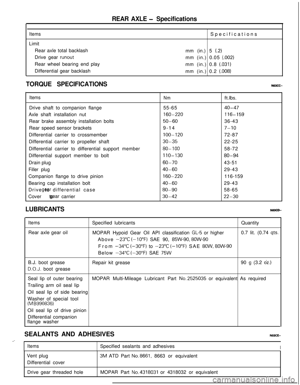
ItemsLimit
Rear axle total backlash
Drive gear
runoutRear wheel bearing end play
Differential gear backlashSpecifications
mm (in.) 5
(.2)mm (in.) 0.05
(.002)mm (in.) 0.8
(.031)mm (in.) 0.2
(.008)
TORQUE SPECIFICATIONS
ItemsNmft.lbs.
Drive shaft to companion flange55-65
40-47Axle shaft installation nut
160-220116-159Rear brake assembly installation bolts
50-6036-43
Rear speed sensor brackets9-14
7-10Differential carrier to crossmember
100-12072-87
Differential carrier to propeller shaft
30-3522-25
Differential carrier to differential support
member80- 10058-72
Differential support member to bolt
110-13080-94Drain plug
60-7043-51
Filler plug40-6029-43
Companion flange to drive pinion
160-220116-159
Bearing cap installation bolt
40-6029-43
Drive to differential case
gear80-9058-65
Cover to carrier
gear30-4222-30
LUBRICANTS
ItemsRear axle gear oilSpecified lubricantsQuantity
MOPAR Hypoid Gear Oil API classification
GL-5 or higher0.7 lit. (0.74 qts.Above
-23°C (-10°F) SAE 90, 85W-90, 8OW-90From
-34°C (-30°F) to -23°C (-10°F) SAE 8OW, 8OW-90Below
-34°C (-30°F) SAE 75WB.J. boot grease
D.O.J. boot greaseRepair kit grease90
g (3.2 dz.)Seal lip of outer bearingMOPAR Multi-Mileage Lubricant Part No.2525035 or equivalent As required
Trailing arm oil seal lip
Oil seal lip of side bearing
Washer of special tool
(M B990836)Oil seal lip of drive pinion
Differential companion
flange washer
SEALANTS AND ADHESIVES
..-
ItemsSpecified sealants and adhesivesIVent plug
Differential cover3M ATD Part
No.8661, 8663 or equivalent
Drive gear threaded holeMOPAR Part
No.4318031 or 4318032 or equivalent
Page 115 of 1216
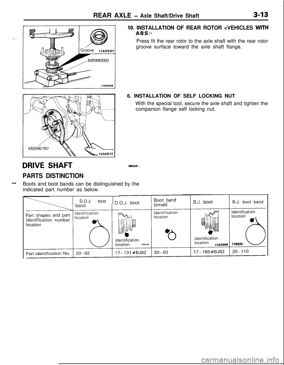
REAR AXLE - Axle Shaft/Drive Shaft3-13
DRIVE SHAFTN03JA--
PARTS DISTINCTION--
Boots and boot bands can be distinguished by the
indicated part number as below.
10. INSTALLATION OF REAR ROTOR
groove surface toward the axle shaft flange.
6. INSTALLATION OF SELF LOCKING NUT
With the special tool, secure the axle shaft and tighten the
companion flange self locking nut.
F
I
IIidentification number
location
1 D.O.J. boot 1 nB.J. boot band