boot MITSUBISHI ECLIPSE 1991 Owner's Guide
[x] Cancel search | Manufacturer: MITSUBISHI, Model Year: 1991, Model line: ECLIPSE, Model: MITSUBISHI ECLIPSE 1991Pages: 1216, PDF Size: 67.42 MB
Page 209 of 1216
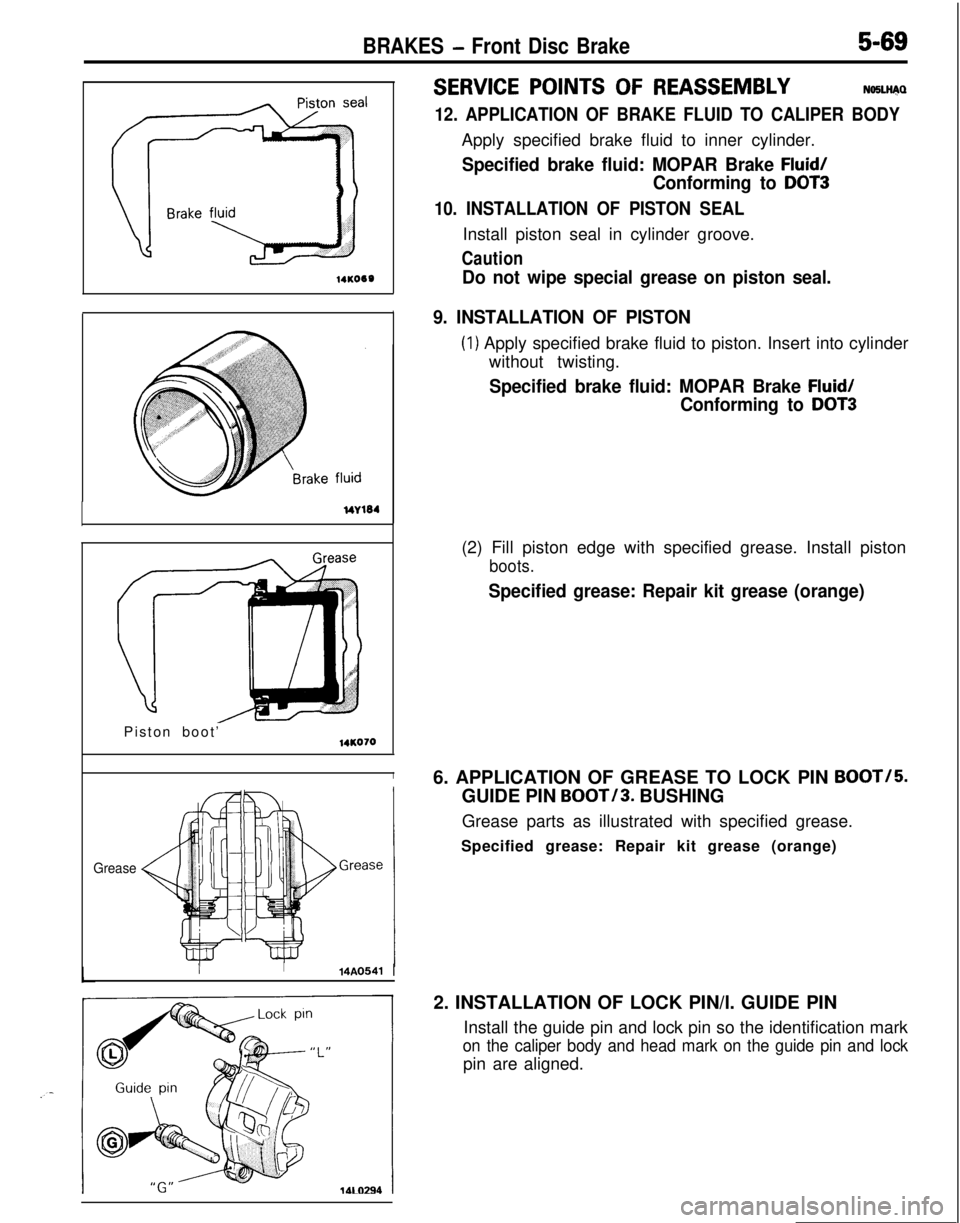
14KO60Do not wipe special grease on piston seal.
BRAKES - Front Disc Brake5-69
SERVICE POINTS OF REASSEMBLYNOSLli@
12. APPLICATION OF BRAKE FLUID TO CALIPER BODYApply specified brake fluid to inner cylinder.
Specified brake fluid: MOPAR Brake Fluid/
Conforming to DOT3
10. INSTALLATION OF PISTON SEALInstall piston seal in cylinder groove.
Caution
9. INSTALLATION OF PISTON
(1) Apply specified brake fluid to piston. Insert into cylinder
without twisting.
Specified brake fluid: MOPAR Brake Fluid/
Conforming to DOT3Piston boot’
14KO70
I
Grease
II14A0541 I(2) Fill piston edge with specified grease. Install piston
boots.
Specified grease: Repair kit grease (orange)6. APPLICATION OF GREASE TO LOCK PIN
BOOT/5.GUIDE PIN
BOOT/3. BUSHING
Grease parts as illustrated with specified grease.
Specified grease: Repair kit grease (orange)
2. INSTALLATION OF LOCK PIN/l. GUIDE PIN
Install the guide pin and lock pin so the identification mark
on the caliper body and head mark on the guide pin and lockpin are aligned.
Page 213 of 1216
BRAKES -Rear Disc Brake5-73
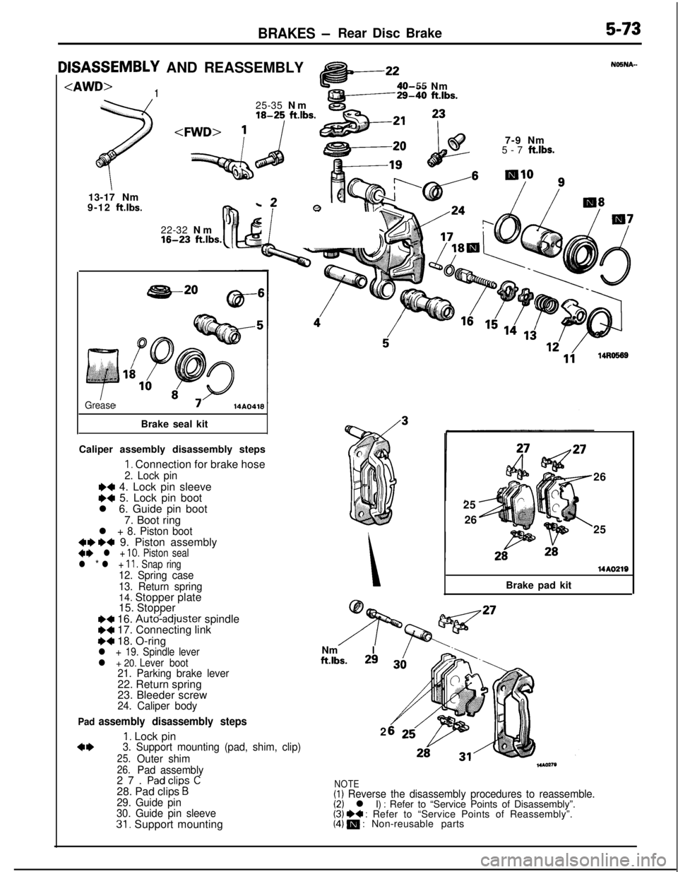
IISASSEMBLY AND REASSEMBLY
125-35 Nm
18-25 ft.lbs.
;
I13-17 Nm
9-12
ftlbs.
c*:O55 Nm29-40 ft.lbs.22-32 Nm
16-23 fi.J,,s.b- Q \\T;17-9 Nm
5-7
ft.lbs.
GreaseBrake seal kit
Caliper assembly disassembly steps
1. Connection for brake hose
2. Lock pin
N 4. Lock pin sleeveM 5. Lock pin boot
l 6. Guide pin boot
7. Boot ring
l + 8. Piston boot+e W+ 9. Piston assembly** l + 10. Piston seal
l * l + Il. Snap ring12. Spring case
13. Return spring14. Stopper plate
15. Stopper
~~ 16. Auto-adjuster spindleI)+ 17. Connecting link
I)+ 18. O-ringl + 19. Spindle leverl + 20. Lever boot21. Parking brake lever22. Return spring
23. Bleeder screw
24. Caliper body
Pad
assembly disassembly steps
1. Lock pinNm
Iftlbs.293.2
*I)3. Support mounting (pad, shim, clip)
25.Outer shim26.Pad assembly27. Padclips C28. Pad clips BNOTE
29. Guide pin
30. Guide pin sleeve
31. Support mounting
(I) Reverse the disassembly procedures to reassemble.(2) l I) : Refer to “Service Points of Disassembly”.(3) H : Refer to “Service Points of Reassembly”.(4) 19 : Non-reusable parts26
25
26
25
Brake pad kit
14AO219
Page 215 of 1216
BRAKES - Rear Disc Brake5-75
- Lever
boot14RDD52
grooves
a
0 0SERVICE POINTS OF REASSEMBLYNiSNDAF
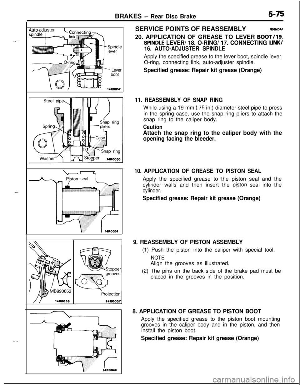
20. APPLICATION OF GREASE TO LEVER
BOOT/19.
SllNDLE LEVER/ 18. O-RING/ 17. CONNECTING LINK/
16. AUTO-ADJUSTER SPINDLEApply the specified grease to the lever boot, spindle lever,
O-ring, connecting link, auto-adjuster spindle.
Specified grease: Repair kit grease (Orange)
11. REASSEMBLY OF SNAP RINGWhile using a 19 mm
(.75 in.) diameter steel pipe to press
in the spring case, use the snap ring pliers to attach the
snap ring to the caliper body.
CautionAttach the snap ring to the caliper body with the
opening facing the bleeder.
10. APPLICATION OF GREASE TO PISTON SEALApply the specified grease to the piston seal and the
cylinder walls and then insert the
pi,ston seal into the
cylinder.
Specified grease: Repair kit grease (Orange)
9. REASSEMBLY OF PISTON ASSEMBLY(1) Push the piston into the caliper with special tool.
NOTEAlign the grooves as illustrated.
(2) The pins on the back side of the brake pad must be
placed in the grooves in the position.
8. APPLICATION OF GREASE TO PISTON BOOTApply the specified grease to the piston boot mounting
grooves in the caliper body and in the piston, and then
install the piston boot.
Specified grease: Repair kit grease (Orange)
Page 216 of 1216
5-76BRAKES - Rear Disc Brake
hide pin end
Caliper supportLock pin end
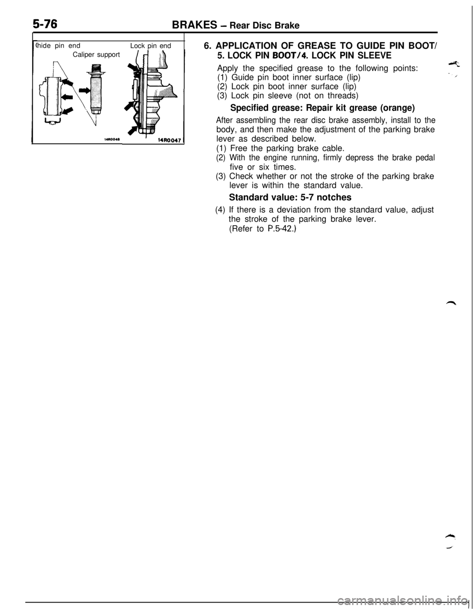
6. APPLICATION OF GREASE TO GUIDE PIN BOOT/
5. LOCK PIN BOOT/4. LOCK PIN SLEEVEApply the specified grease to the following points:
(1) Guide pin boot inner surface (lip)
(2) Lock pin boot inner surface (lip)
(3) Lock pin sleeve (not on threads)
Specified grease: Repair kit grease (orange)
After assembling the rear disc brake assembly, install to thebody, and then make the adjustment of the parking brake
lever as described below.
(1) Free the parking brake cable.
(2) With the engine running, firmly depress the brake pedalfive or six times.
(3) Check whether or not the stroke of the parking brake
lever is within the standard value.
Standard value: 5-7 notches
(4) If there is a deviation from the standard value, adjust
the stroke of the parking brake lever.
(Refer to
P.5-42.)
Page 241 of 1216
CLUTCH - Clutch Master Cylinder6-l 1
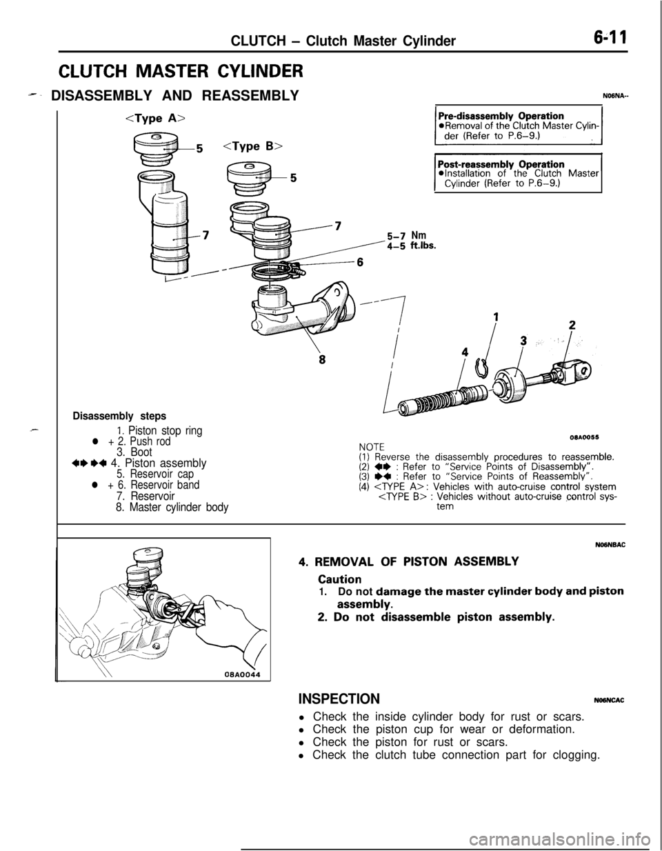
CLUTCH MASTER CYLINDER
-. DISASSEMBLY AND REASSEMBLYNOGNA-
Disassembly steps
1. Piston stop ringl + 2. Push rod3. Boot
+e W 4. Piston assembly5. Reservoir cap
l + 6. Reservoir band
7. Reservoir
8. Master cylinder body
@Installation of the Clutch MasterCylinder (Refer to P.6-9.)
Nmftlbs.
NOTE(I) Reverse the disassembly procedures to reassemble.(2)+e: Refer Points of (3)I)+: Refer to “Service Points of Reassembly’.(4)
\\08AOOi4
NO6NBAC
4.REMOVALOFPISTON ASSEMBLY
Caution
1.Do not damagethe master cylinder body and piston
assembly.
2. Do not disassemble piston assembly.
INSPECTIONNO9NCACl Check the inside cylinder body for rust or scars.
l Check the piston cup for wear or deformation.
l Check the piston for rust or scars.
l Check the clutch tube connection part for clogging.
Page 242 of 1216
6-12CLUTCH - Clutch Master CylinderResew&r
bandk
oaA0058
08Y517
Grease
SERVICE POINTS OF REASSEMBLYNaaNciAN
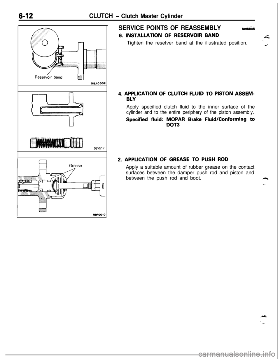
6. INSTALLATION OF RESERVOIR BAND
Tighten the resetver band at the illustrated position.
4. APPLICATION OF CLUTCH FLUID TO PISTON ASSEM-
BLYApply specified clutch fluid to the inner surface of the
cylinder and to the entire periphery of the piston assembly.
Specified fluid: MOPAR Brake Fluid/Conforming to
DOT3
2. APPLICATION OF GREASE TO PUSH RODApply a suitable amount of rubber grease on the contact
surfaces between the damper push rod and piston and
between the push rod and boot.
Page 243 of 1216
CLUTCH - Clutch Release Cvlinder6-13
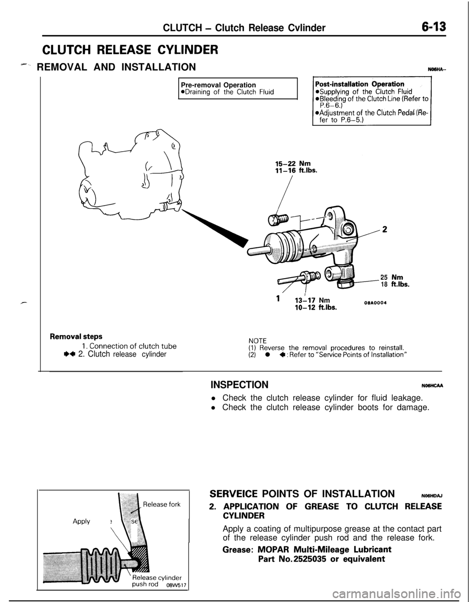
CLUTCH RELEASE CYLINDER
-‘- REMOVAL AND INSTALLATIONNaaHA--Pre-removal Operation
@Draining of the Clutch Fluid@Supplying of the Clutch Fluid@Bleeding of the Clutch Line (Refer to
@Adjustment of the Clutch Pedal (Re-
2518EL.
113117 Nm
IO-12 ftlbs.08A0004
Removal steps
1. Connection of clutch tube
I)4 2. Clutch release cylinder
NOTE(I) Reverse the removal procedures to reinstall.(2) l * : Refer to “Service Points of Installation”
INSPECTIONNOMCAAl Check the clutch release cylinder for fluid leakage.
l Check the clutch release cylinder boots for damage.
SERVEICE POINTS OF INSTALLATIONNO6HDAJ
2. APPLICATION OF GREASE TO CLUTCH RELEASE
CYLINDERApply grease
\\ :\Apply a coating of multipurpose grease at the contact part
of the release cylinder push rod and the release fork.
Grease: MOPAR Multi-Mileage Lubricant
Part No.2525035 or equivalent
Page 244 of 1216
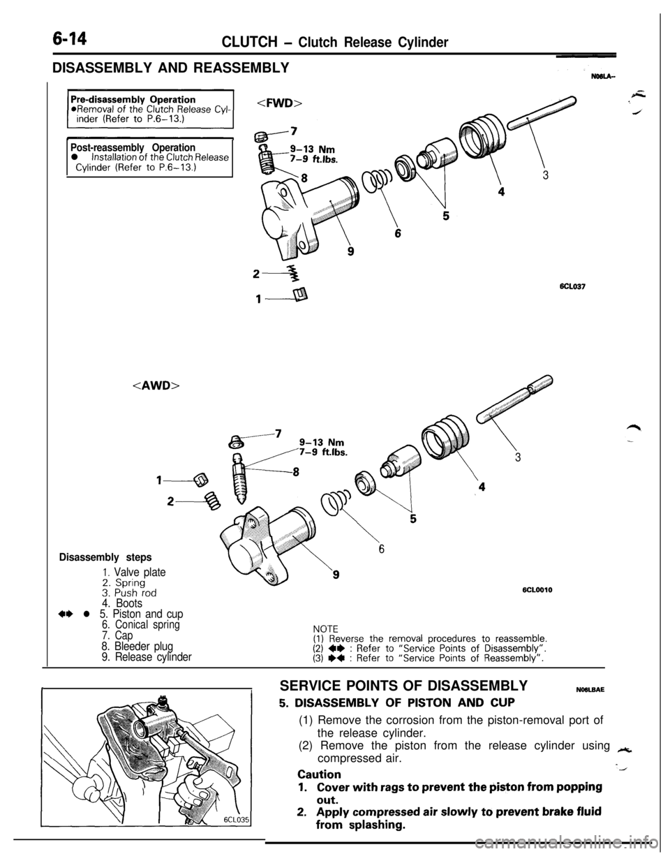
6-14CLUTCH - Clutch Release CylinderDISASSEMBLY AND REASSEMBLY
Post-reassembly Operationl installation of the Clutch ReleaseCylinder (Refer to P.6-13.)
,, #,,“”
7
3
2-36CLO37
,---a
#,J,,, ‘::.”/,,,,d$’ ’.,:..a
<
/ : i 01‘, ., 1
3
Disassembly steps
I. Valve plate2. Spring
6
3. Push rod4. Boots
6CLOOlO
*+ l 5. Piston and cup6. Conical spring
7. Cap
8. Bleeder plug
9. Release cylinder
NOTE(1) Reverse the removal procedures to reassemble.(2) W : Refer to “Service Points of Disassembly”.(3) I)4 : Refer to “Service Points of Reassembly”.
rISERVICE POINTS OF DISASSEMBLYNOOLBAE
5. DISASSEMBLY OF PISTON AND CUP(1) Remove the corrosion from the piston-removal port of
the release cylinder.
(2) Remove the piston from the release cylinder using
++,compressed air.
-JCaution
1.Cover with rags to prevent the piston from popping
out.
2.Apply compressed air slowly to prevent brake fluidfrom
splashing.
Page 246 of 1216
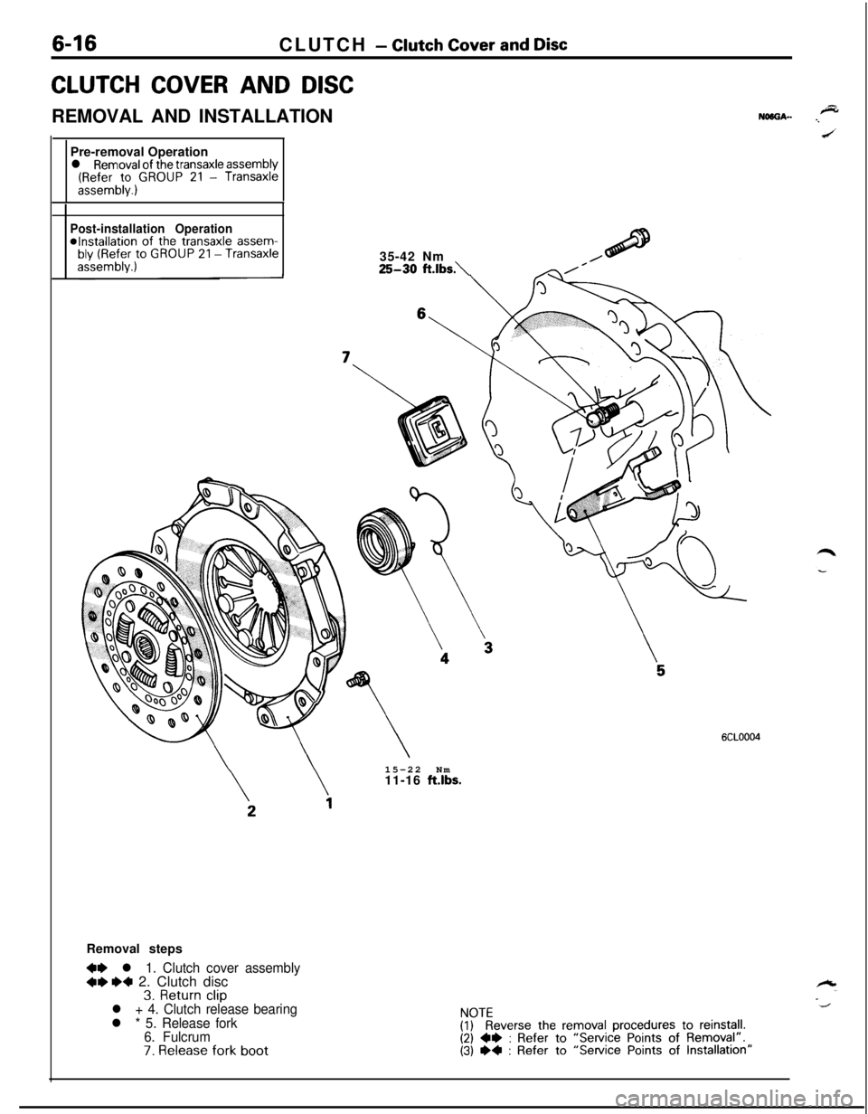
6-16CLUTCH - Clutch Cover and Disc
CLUTCH COVER AND DISCREMOVAL AND INSTALLATION
Pre-removal Operation
l Removal of the transaxle assembly(Refer to GROUP 21 - Transaxleassembly.)
Post-installation Operation*Installation of the transaxle assem-bly (Refer to GROUP 21 -Transaxleassembly.)35-42 Nm25-30 ft.lbs.\15-22 Nm
11-16
ft.lbs.
6CLOOO4Removal steps
+e l 1. Clutch cover assembly+**a 2. Clutch disc3. Return clipl + 4. Clutch release bearingl * 5. Release fork
6. Fulcrum
7. Release fork boot
FyEeverse the removal procedures to reinstall.(2) 4e : Refer to “Service Points of Removal”.(3) I)4 : Refer to “Service Points of Installation”
Page 600 of 1216
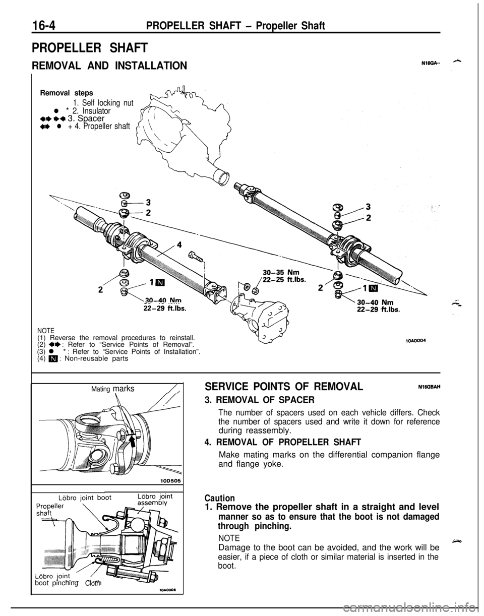
16-4PROPELLER SHAFT - Propeller Shaft
PROPELLER SHAFT
REMOVAL AND INSTALLATIONNlffiA--
Removal steps
1. Self locking nut
l * 2. Insulator*I)+* 3. Spacer+e l + 4. Propeller shaft
- -. - . . .ii-29 ftlbs.
NOTE(1) Reverse the removal procedures to reinstall.
(2)
+* : Refer to “Service Points of Removal”.
(3) l * : Refer to “Service Points of Installation”.
(4) m : Non-reusable parts
lOAOOO4
Mating marks/,
lOD505
LBbro jointboot pinching
Cloth
SERVICE POINTS OF REMOVALNlEGBAH
3. REMOVAL OF SPACER
The number of spacers used on each vehicle differs. Check
the number of spacers used and write it down for referenceduring reassembly.
4. REMOVAL OF PROPELLER SHAFTMake mating marks on the differential companion flange
and flange yoke.
Caution1. Remove the propeller shaft in a straight and level
manner so as to ensure that the boot is not damaged
through pinching.
NOTEDamage to the boot can be avoided, and the work will be
easier, if a piece of cloth or similar material is inserted in the
boot.