boot MITSUBISHI ECLIPSE 1991 Workshop Manual
[x] Cancel search | Manufacturer: MITSUBISHI, Model Year: 1991, Model line: ECLIPSE, Model: MITSUBISHI ECLIPSE 1991Pages: 1216, PDF Size: 67.42 MB
Page 603 of 1216
PROPELLER SHAFT - Propeller Shaft
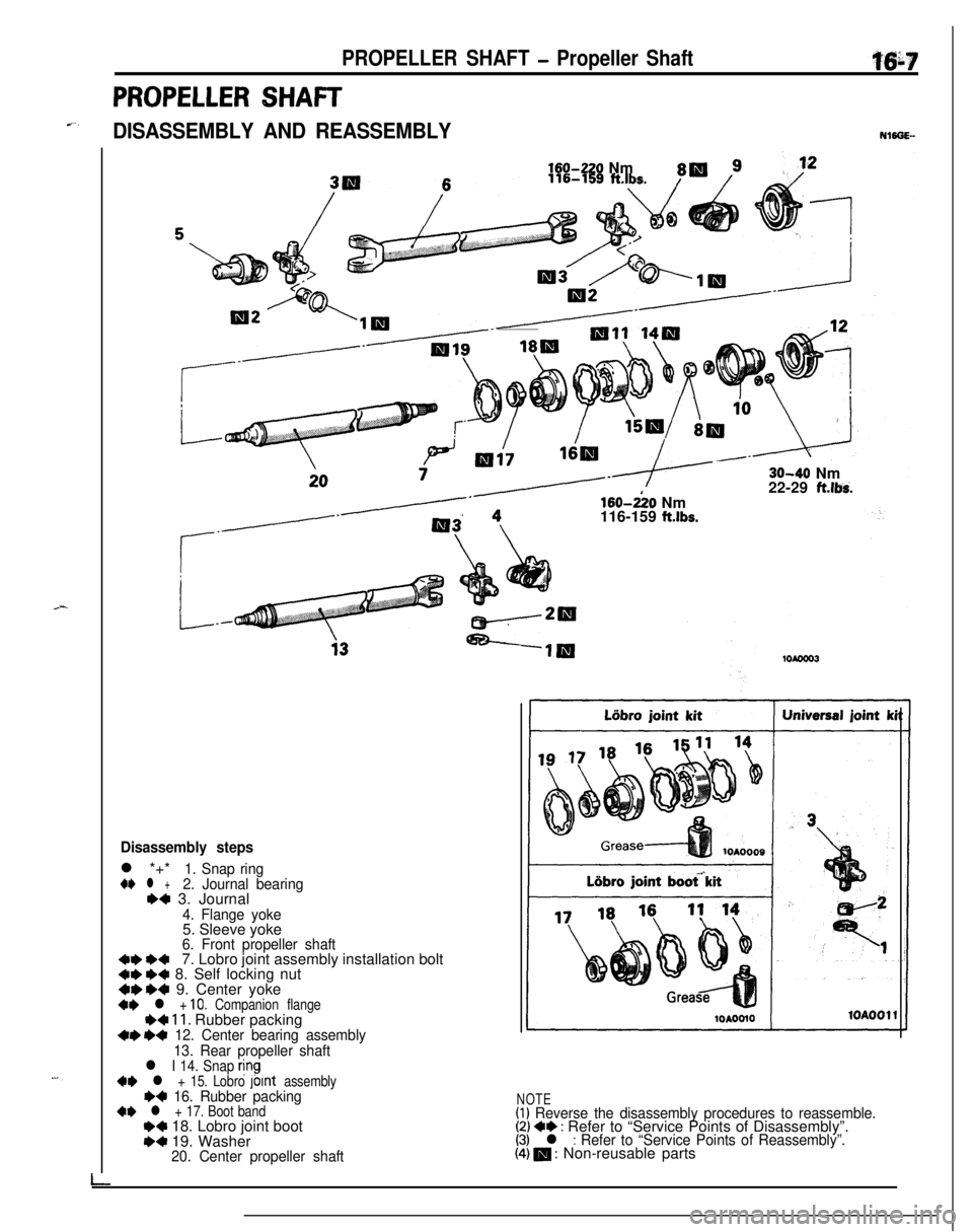
PROPELLER SHAFT
e-,DISASSEMBLY AND REASSEMBLY
l-
160420 Nm160-&O Nm
116-159
ft.lbs.30-40 Nm
22-29
ft.lbs.
Disassembly stepsl *+*
1. Snap ring+I) l +2. Journal bearing++ 3. Journal
4. Flange yoke5. Sleeve yoke
6. Front propeller shaft41) +47. Lobro joint assembly installation bolt~~ +4 8. Self locking nut4r)+4 9. Center yokea* l + 10. Companion flange~~ 11. Rubber packing++ I)+ 12. Center bearing assembly
13. Rear propeller shaft
l I 14. Snap rjng+* l + 15. Lobro fount assemblyH 16. Rubber packing~~ l + 17. Boot band++ 18. Lobro joint boot~~ 19. Washer20. Center propeller shaft
NOTE(1) Reverse the disassembly procedures to reassemble.(2) ++ : Refer to “Service Points of Disassembly”.(3) l : Refer to “Service Points of Reassembly”.(4) m : Non-reusable parts
Page 605 of 1216
PROPELLER SHAFT - Propeller ShaftMating marks
I1
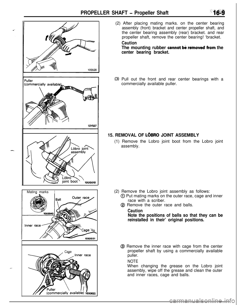
, Caae(2) After placing mating marks. on the center bearing
assembly (front) bracket and center propeller shaft, andthe center bearing assembly (rear) bracket. and rear
propeller shaft, remove the center bearing! ‘bracket.
Caution
The mounting rubber canndt b& rimoved’ frbm the
center bearing bracket.
(3) Pull out the front and rear center bearings with a
commercially available puller.
15. REMOVAL OF LOBRO JOINT ASSEMBLY(1) Remove the Lobro joint boot from the Lobro joint
assembly.(2) Remove the Lobro joint assembly as follows:
@ Put mating marks on the outer race, cage and inner
race with a scriber.
@ Remove the outer race and balls.
Caution
Note the positions of balls so that they can be
reinstalled in their’ original positions.@ Remove the inner race with cage from the center
propeller shaft by using a commercially available
puller.
NOTEWhen changing the grease on the Lobro joint
assembly, wipe off the grease and clean the outer
and inner races, cage and balls.
Page 606 of 1216
16-10PROPELLER SHAFT - ProDeller Shaft
Ldbro joint/ assemblvcommercially avail
10x0021
10x0018
Washer
Tape
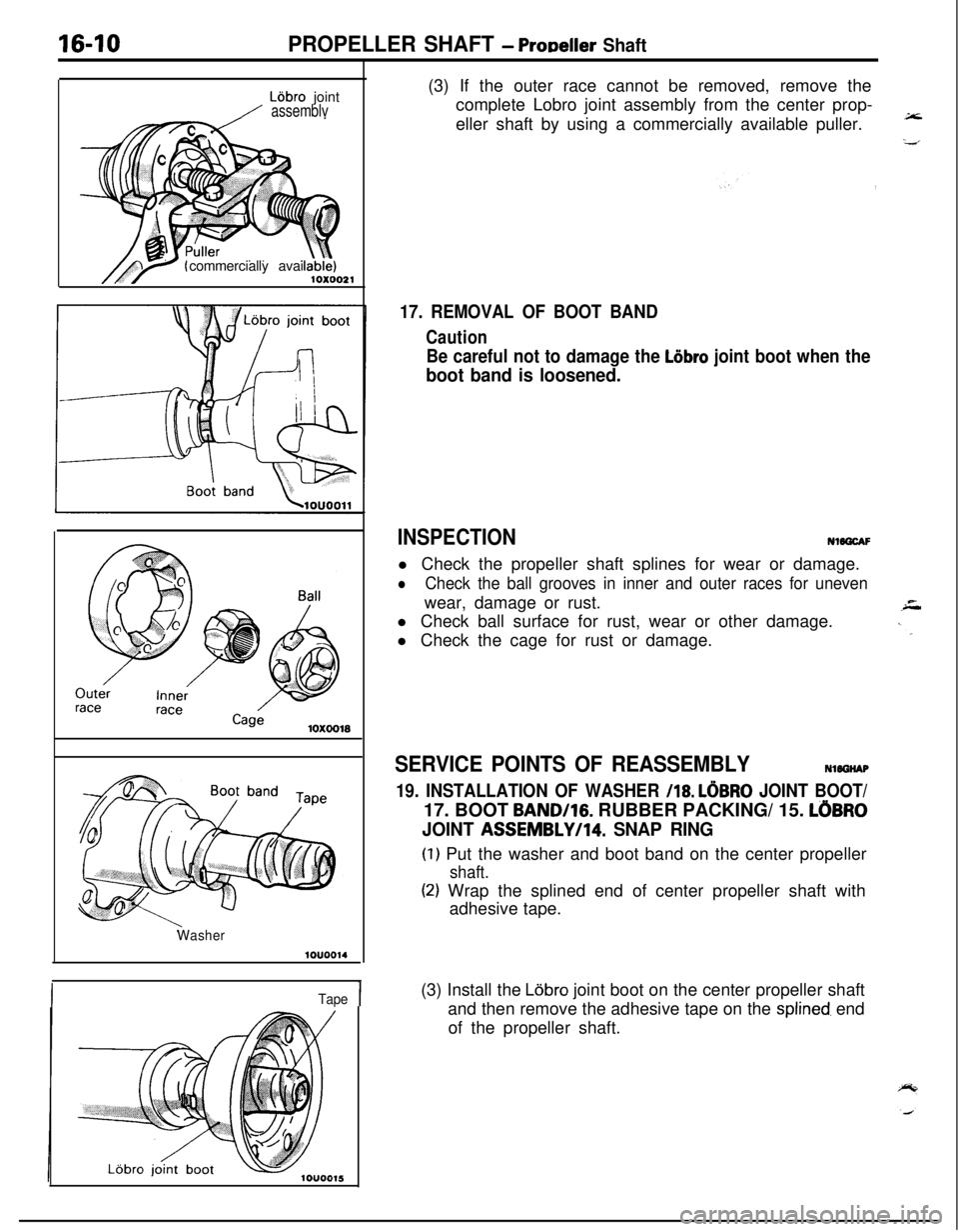
I(3) If the outer race cannot be removed, remove the
complete Lobro joint assembly from the center prop-
eller shaft by using a commercially available puller.
17. REMOVAL OF BOOT BAND
Caution
Be careful not to damage the Liibro joint boot when the
boot band is loosened.
INSPECTIONNWGCAF
l Check the propeller shaft splines for wear or damage.
lCheck the ball grooves in inner and outer races for unevenwear, damage or rust.
l Check ball surface for rust, wear or other damage.
l Check the cage for rust or damage.
SERVICE POINTS OF REASSEMBLYNlOGHAP
19. INSTALLATION OF WASHER /18. LOBRO JOINT BOOT/17. BOOT
BAND/lG. RUBBER PACKING/ 15. LOBRO
JOINT ASSEMBLYI14. SNAP RING
(I) Put the washer and boot band on the center propeller
shaft.
(2) Wrap the splined end of center propeller shaft with
adhesive tape.
(3) Install the Lijbro joint boot on the center propeller shaft
and then remove the adhesive tape on the
splined, end
of the propeller shaft.
Page 607 of 1216
PROPELLER SHAFT - ProDeller ShaftIS-91
10X0018Inner race
I BallRecessed end
of inner race
Chamfered en
10x0040
Rubber
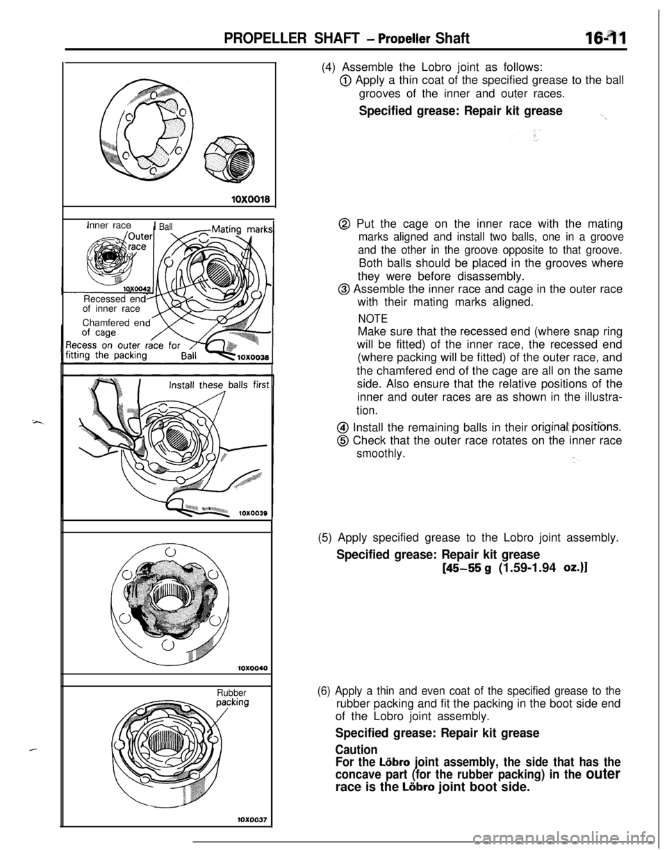
10x0037(4) Assemble the Lobro joint as follows:
@ Apply a thin coat of the specified grease to the ball
grooves of the inner and outer races.
Specified grease: Repair kit grease._,
@ Put the cage on the inner race with the mating
marks aligned and install two balls, one in a groove
and the other in the groove opposite to that groove.Both balls should be placed in the grooves where
they were before disassembly.
@ Assemble the inner race and cage in the outer race
with their mating marks aligned.
NOTEMake sure that the
recess.ed end (where snap ring
will be fitted) of the inner race, the recessed end
(where packing will be fitted) of the outer race, and
the chamfered end of the cage are all on the same
side. Also ensure that the relative positions of the
inner and outer races are as shown in the illustra-
tion.
@I Install the remaining balls in their original; positibns.
@ Check that the outer race rotates on the inner race
smoothly.‘l.(5) Apply specified grease to the Lobro joint assembly.
Specified grease: Repair kit grease
[45-55 g (1.59-1.94 oz.)1
(6) Apply a thin and even coat of the specified grease to therubber packing and fit the packing in the boot side end
of the Lobro joint assembly.
Specified grease: Repair kit grease
Caution
For the
L6bro joint assembly, the side that has the
concave part (for the rubber packing) in the
outerrace is the
Liibro joint boot side.
Page 608 of 1216
16-12PROPELLER SHAFT - Propeller Shaft
10X0036Mounting boltsLijbro joint bootlOUOO16
clip
position1 ABoot band 1
.:,q,,
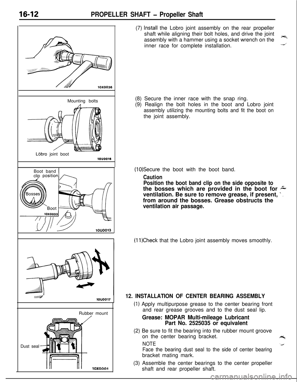
-
10x0001(7)
Install the Lobro joint assembly on the rear propeller
shaft while aligning their bolt holes, and drive the joint
assembly with a hammer using a socket wrench on the
;rinner race for complete installation.-4’
(8) Secure the inner race with the snap ring.
(9) Realign the bolt holes in the boot and Lobro joint
assembly utilizing the mounting bolts and fit the boot onthe joint assembly.
(1O)Secure the boot with the boot band.
Caution
Position the boot band clip on the side opposite tothe bosses which are provided in the boot for
Aventilation. Be sure to remove grease, if present,
’ _from around the bosses. Grease obstructs the
ventilation air passage.
(11)Check that the Lobro joint assembly moves smoothly.
12. INSTALLATION OF CENTER BEARING ASSEMBLY
(1) Apply multipurpose grease to the center bearing front
and rear grease grooves and to the dust seal lip.
Grease: MOPAR Multi-mileage Lubricant
Part No. 2525035 or equivalent(2) Be sure to fit the bearing into the rubber mount groove
on the center bearing bracket.
e;
NOTE-4
Face the bearing dust seal to the side of center bearingbracket mating mark.
(3) Assemble the center bearings to the center propeller
shaft and rear propeller shaft.
Page 609 of 1216
PROPELLER SHAFT - Propeller Shaft
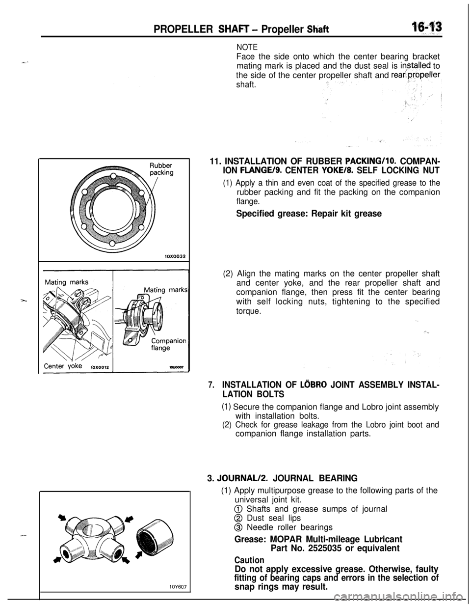
NOTEFace the side onto which the center bearing bracket
mating mark is placed and the dust seal is
in,stalled to
the side of the center propeller shaft and
rear.propeller
10X0032
1 OY607
shaft.
11. INSTALLATION OF RUBBER PACKING/lo. COMPAN-
ION FLANGE/S. CENTER YOKE/8. SELF LOCKING NUT
(1) Apply a thin and even coat of the specified grease to therubber packing and fit the packing on the companion
flange.
Specified grease: Repair kit grease(2) Align the mating marks on the center propeller shaft
and center yoke, and the rear propeller shaft and
companion flange, then press fit the center bearing
with self locking nuts, tightening to the specified
torque.
,.
7.INSTALLATION OF LOBRO JOINT ASSEMBLY INSTAL-
LATION BOLTS
(1) Secure the companion flange and Lobro joint assembly
with installation bolts.
(2) Check for grease leakage from the Lobro joint boot andcompanion flange installation parts.
3. JOURNAL/2. JOURNAL BEARING(1) Apply multipurpose grease to the following parts of the
universal joint kit.
@ Shafts and grease sumps of journal
@ Dust seal lips
@ Needle roller bearings
Grease: MOPAR Multi-mileage Lubricant
Part No. 2525035 or equivalent
Caution
Do not apply excessive grease. Otherwise, faulty
fitting of bearing caps and errors in the selection of
snap rings may result.
Page 666 of 1216
19-18STEERING - Steering Wheel and Shaft
DISASSEMBLY AND REASSEMBLYNlBGE-
4-5
Nm3-4;lbs. -6
18-z.
11-14 ft.lbs.
13AO287
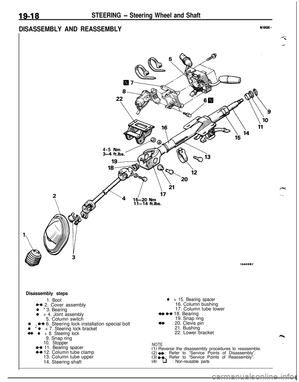
Disassembly steps
1. Boot*+ 2. Cover assemblyl * 3. Bearingl + 4. Joint assembly5. Column switch
l ,
.+ 6. Steering lock installation special boltl * l + 7. Steering lock bracket+I) l + 8. Steering lock9. Snap ring
10. Stopper~~ 11. Bearing spacerW 12. Column tube clamp
13. Column tube upper
14. Steering shaft
l + 15. Bearing spacer16. Column bushing
17. Column tube tower
4, ,+ 18. Bearing
19. Snap ring
4,20. Clevis pin
21. Bushing
22. Lower bracket
NOTE(I 1 Reverse the disassembly procedures to reassemble.(2) +I) : Refer to “Service Points of Disassembly”.(3) I)+ : Refer to “Service Points of Reassembly”.(4) q : Non-reusable parts
‘I
Page 670 of 1216
19-22STEERING - Manual Steering Gear Box
13Roo7!
J Mow&g clamp
SERVICE POINTS OF REMOVAL.dlSLl$iF
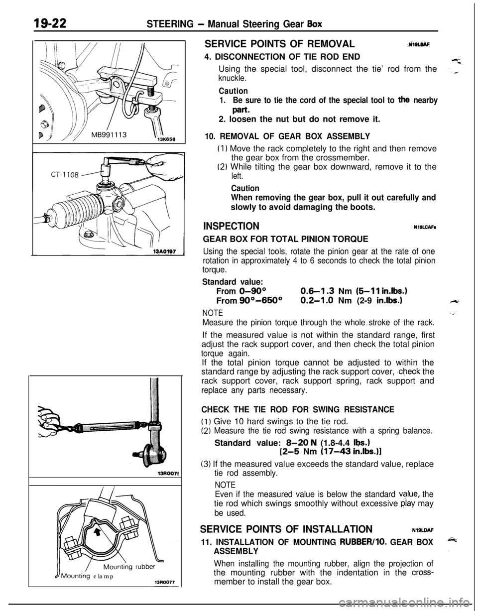
4. DISCONNECTION OF TIE ROD END
Using the special tool, disconnect the tie’ rod from the
knuckle.
Caution
1.Be sure to tie the cord of the special tool to the nearby
part*2. loosen the nut but do not remove it.
10. REMOVAL OF GEAR BOX ASSEMBLY
(1) Move the rack completely to the right and then remove
the gear box from the crossmember.
(2) While tilting the gear box downward, remove it to the
left.
Caution
When removing the gear box, pull it out carefully andslowly to avoid damaging the boots.
INSPECTIONNlSLCAFaGEAR BOX FOR TOTAL PINION TORQUE
Using the special tools, rotate the pinion gear at the rate of one
rotation in approximately 4 to 6 seconds to check the total pinion
torque.
Standard value:
From
0-90°0.6-l .3 Nm (5-11 in.lbs.1From
90°-650°0.2-1.0 Nm (2-9 in.lbs.1
NOTE
Measure the pinion torque through the whole stroke of the rack.If the measured value is not within the standard range, first
adjust the rack support cover, and then check the total pinion
torque again.If the total pinion torque cannot be adjusted to within the
standard range by adjusting the rack support cover,
,check the
rack support cover, rack support spring, rack support and
replace any parts necessary.
CHECK THE TIE ROD FOR SWING RESISTANCE
(1) Give 10 hard swings to the tie rod.
(2) Measure the tie rod swing resistance with a spring balance.Standard value:
B-20 N (1.8-4.4 Ikw.1
12-5 Nm (17-43 in.lbs.)l
(3) If the measured value exceeds the standard value, replace
tie rod assembly.
NOTE
Even if the measured value is below the standard vglue, thetie rod which swings smoothly without excessive
clay may
be used.
SERVICE POINTS OF INSTALLATIONNlSLDAF
11. INSTALLATION OF MOUNTING RUBBER/lo. GEAR BOX
ASSEMBLY
When installing the mounting rubber, align the projection ofthe mounting rubber with the indentation in the
cross-member to install the gear box.
Page 677 of 1216
STEERING - Power Steering Gear Box
lS1017S
I /Mounting rubber
IIMdting clamp13Roo77
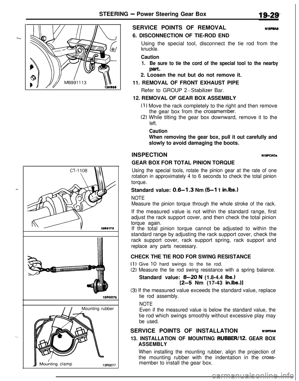
5SERVICE POINTS OF REMOVAL
NIBPNAB6. DISCONNECTION OF TIE-ROD END
Using the special tool, disconnect the tie rod from the
knuckle.
Caution
1.Be sure to tie the cord of the special tool to the nearby
part.2. Loosen the nut but do not remove it.
11. REMOVAL OF FRONT EXHAUST PIPE
Refer to GROUP
2-Stabilizer Bar.
12. REMOVAL OF GEAR BOX ASSEMBLY
(I 1 Move the rack completely to the right and then remove
the gear box from the
crossmember.
(2) While tilting the gear box downward, remove it to the
left.
Caution
When removing the gear box, pull it out carefully andslowly to avoid damaging the boots.
INSPECTION
NlSPCADaGEAR BOX FOR TOTAL PINION TORQUE
Using the special tools, rotate the pinion gear at the rate of one
rotation in approximately 4 to 6 seconds to check the total pinion
torque.Standard value:
0.6-l .3 Nm (5-l 1 in.lbs.1
NOTE
Measure the pinion torque through the whole stroke of the rack.If the measured value is not within the standard range, first
adjust the rack support cover, and then check the total pinion
torque again.If the total pinion torque cannot be adjusted to within the
standard range by adjusting the rack support cover, check the
rack support cover, rack support spring, rack support and
replace any parts necessary.CHECK THE TIE ROD FOR SWING RESISTANCE
(1) Give 10 hard swings to the tie rod.I
(2) Measure the tie rod swing resistance with a spring balance.
’Standard value: 8-20 N (1.8-4.4 Ibs.)
12-5 Nm (17-43 in.lbs.)l
(3) If the measured value exceeds the standard value, replace
tie rod assembly.
NOTE
Even if the measured value is below the standard value, thetie rod which swings smoothly without excessive play may
be used.SERVICE POINTS OF INSTALLATION
Nl9PDA9
13. INSTALLATION OF MOUNTING RUBBER/lZ. GEAR BOX
ASSEMBLY
When installing the mounting rubber, align the projection ofthe mounting rubber with the indentation in the
cross-member to install the gear box.
Page 679 of 1216
STEERING - Power Steering Gear Box
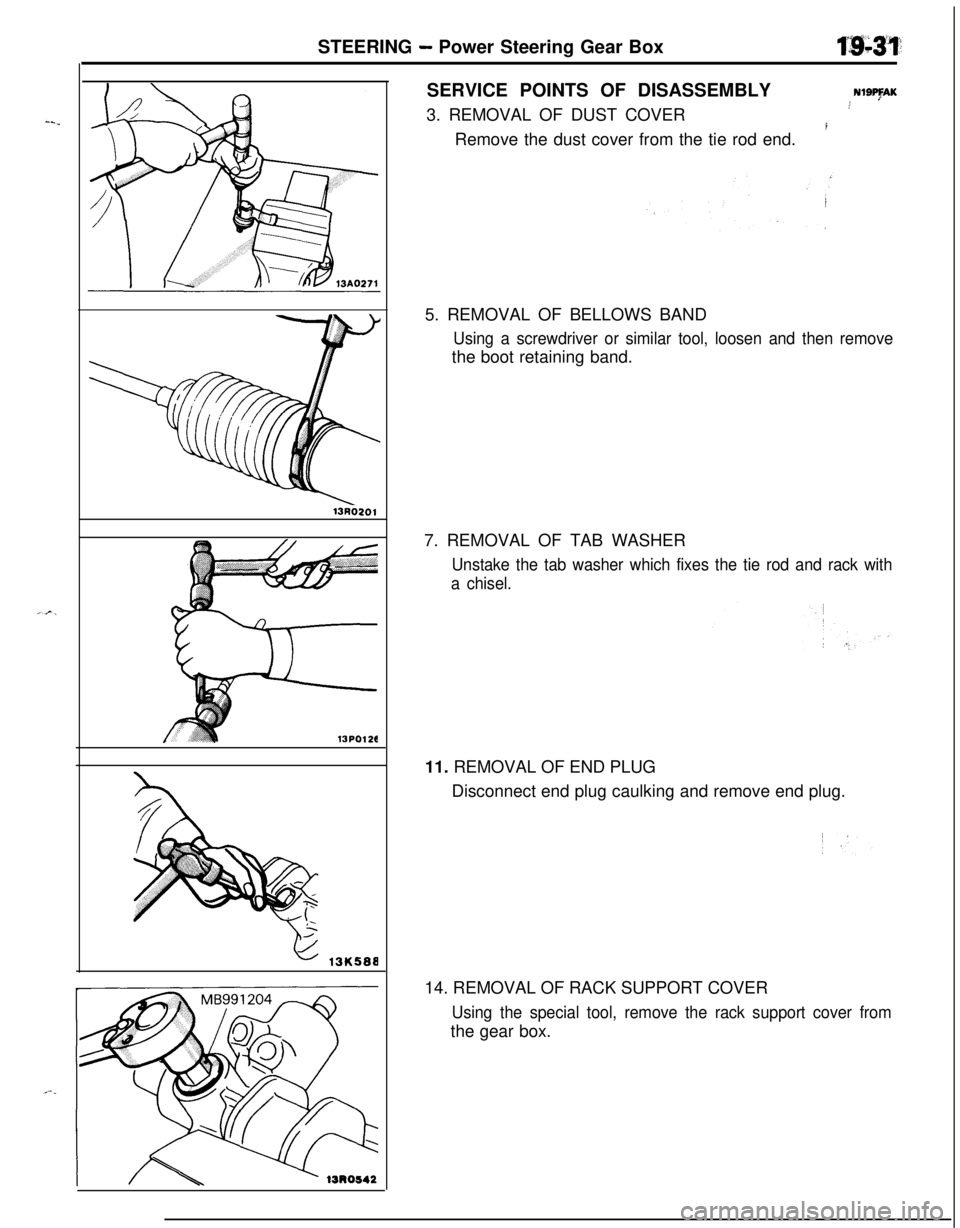
13PO126SERVICE POINTS OF DISASSEMBLY
NISAK3. REMOVAL OF DUST COVER.4
IRemove the dust cover from the tie rod end.
5. REMOVAL OF BELLOWS BAND
Using a screwdriver or similar tool, loosen and then removethe boot retaining band.
7. REMOVAL OF TAB WASHER
Unstake the tab washer which fixes the tie rod and rack with
a chisel.11. REMOVAL OF END PLUG
Disconnect end plug caulking and remove end plug.
14. REMOVAL OF RACK SUPPORT COVER
Using the special tool, remove the rack support cover fromthe gear box.