service MITSUBISHI ECLIPSE 1991 Owner's Manual
[x] Cancel search | Manufacturer: MITSUBISHI, Model Year: 1991, Model line: ECLIPSE, Model: MITSUBISHI ECLIPSE 1991Pages: 1216, PDF Size: 67.42 MB
Page 45 of 1216
LUBRICATION AND MAINTENANCE - Maintenance ServiceO:lllO.AUTOMATIC TRANSAXLE (Inspect fluid
I~~+v~!1. Drive until the fluid temperature reaches the usual
temperature
[70-80°C (160- 18O”F)l.2. Place vehicle on level floor.
3.Move selector lever sequentially to every position to fill
torque converter and hydraulic
circuitwith fluid, then
place lever in“N” Neutral position. This operation is
necessary to be sure that fluid level check is accurate.
4.Before removing dipstick, wipe all dirt from area arounddipstick. Then take out the dipstick and check the
condition of the fluid.
The transaxle should be overhauled under the following
conditions.l If there is a “burning” odor.
l If the fluid color has become noticeably blacker.
l If there is a noticeably great amount of metal
particles in the fluid.
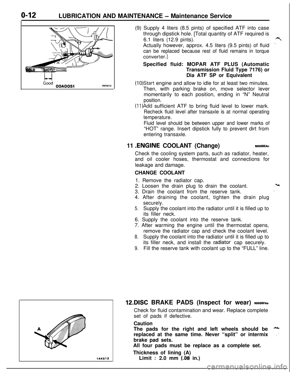
5.Check to see if fluid level is in “HOT” range on dipstick.If fluid level is low, add ATF until level reaches “HOT”
range.Low fluid level can cause a variety of conditions
because it allows pump to take in air along with fluid. Airtrapped in hydraulic circuit forms bubbles which make
fluid spongy. Therefore, pressures will be erratic.
Improper filling can also raise fluid level too high. Whentransaxle has too much fluid, gears churn up foam and
cause same conditions which occur with low fluid level,resulting in accelerated deterioration of ATF.
transmission fluid.
In either case, air bubbles can cause overheating, fluid
oxidation, which can interfere with normal valve, clutch,and servo operation. Foaming can also result in fluid
escaping from transaxle vent where it may be mistakenfor a leak.
6. Be sure to examine fluid on dipstick closely.lO.AUTOMATIC TRANSAXLE (Change fluid)
Drain the fluid and check whether there is any evidence of
contamination.
Replenish with new fluid after the cause of any contamina-tion has been corrected.
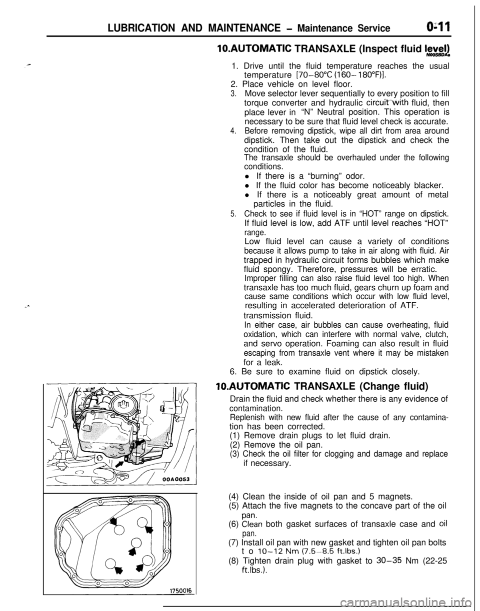
(1) Remove drain plugs to let fluid drain.
(2) Remove the oil pan.
(3) Check the oil filter for clogging and damage and replaceif necessary.
(4) Clean the inside of oil pan and 5 magnets.
(5) Attach the five magnets to the concave part of the oil
(6)
Elan both gasket surfaces of transaxle case and oil
pan.(7) Install oil pan with new gasket and tighten oil pan bolts
to
IO-12 Nm (7.5-8.5 ft.lbs.1(8) Tighten drain plug with gasket to
30-35 Nm (22-25
ftlbs.).
Page 46 of 1216
LUBRICATION AND MAINTENANCE - Maintenance Service
L-4GoodOOA0051C9FW1014K512(9) Supply 4 liters (8.5 pints) of specified ATF into case
through dipstick hole. [Total quantity of ATF required is
6.1 liters (12.9 pints).
Actually however, approx. 4.5 liters (9.5 pints) of fluid
can be replaced because rest of fluid remains in torque
converter.]Specified fluid: MOPAR ATF PLUS (Automatic
Transmission Fluid Type 7176) or
Dia ATF SP or Equivalent
(10)Start engine and allow to idle for at least two minutes.
Then, with parking brake on, move selector lever
momentarily to each position, ending in “N” Neutral
position.
(1 l)Add sufficient ATF to bring fluid level to lower mark.
Recheck fluid level after transaxle is at normal operating
temperature.
Fluid level should be between upper and lower marks of“HOT” range. Insert dipstick fully to prevent dirt from
entering transaxle.
11 .ENGINE COOLANT (Change)NOOSBEAcCheck the cooling system parts, such as radiator, heater,
and oil cooler hoses, thermostat and connections for
leakage and damage.
CHANGE COOLANT
1. Remove the radiator cap.
2. Loosen the drain plug to drain the coolant.
3. Drain the coolant from the reserve tank.
4. After draining the coolant, tighten the drain plug
securely.
5.Supply the coolant into the radiator until it is filled up to
its filler neck.
6. Supply the coolant into the reserve tank.
7. After warming the engine until the thermostat opens,
remove the radiator cap and check the coolant level.
8.Supply the coolant into the radiator until it is filled up to
its filler neck, and install the
.radiator, cap securely.
9.Fill the reserve tank with coolant up to the “FULL” line.12DISC BRAKE PADS (Inspect for wear)
NOOSBFA~Check for fluid contamination and wear. Replace complete
set of pads if defective.
Caution
The pads for the right and left wheels should be
replaced at the same time. Never “split” or intermix
brake pad sets.
All four pads must be replace as a complete set.
Thickness of lining (A)
Limit
:2.0 mm (.08 in.)
Page 47 of 1216
LUBRICATION AND MAINTENANCE - Maintenance Serviceo-13
OOAOlB6
13.BRAKE HOSES (Check for deteriorati.on or
leaks)NwBBnAs
Inspection of brake hoses and tubing should be included inall brake service operations.
The hoses should be checked for:
1. Correct length, severe surface cracking, pulling, scuf-
fing or worn spots. (If the fabric casing of the hoses is
exposed by cracks of abrasion in the rubber hose cover,
the hoses should be replaced. Eventual deterioration ofhose may occur with possible bursting failure.)
2. Faulty installation, casing twisting or interference with
wheel, tire of chassis.
14.BALL JOINT AND STEERING LINKAGE SEALS
(Inspect for grease leaks and damage)
NWSBJAb1. These components, which are permanently lubricated
at the factory, do not require periodic lubrication.
Damaged seals and boots should be replaced to
prevent leakage or contamination of the grease.
2. Inspect the dust cover and boots for proper sealing,
leakage and damage. Replace them if defective.
15.DRIVE SHAFT BOOTS (Inspect for grease leaksand damage)
NWSBJAc1. These components, which are permanently lubricated
at the factory, do not require periodic lubrication.
Damaged boots should be replaced to prevent leakage
or contamination of the grease.
2. Inspect the boots for proper sealing, leakage and
damage. Replace it if defective.
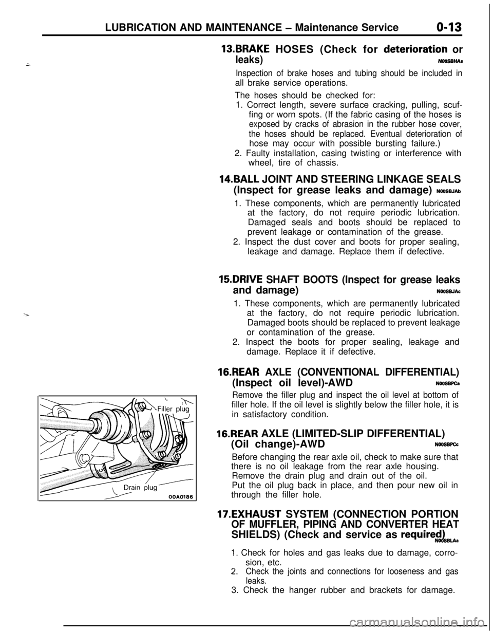
16.REAR AXLE (CONVENTIONAL DIFFERENTIAL)(Inspect oil level)-AWD
NWSBFCa
Remove the filler plug and inspect the oil level at bottom offiller hole. If the oil level is slightly below the filler hole, it is
in satisfactory condition.
16.REAR AXLE (LIMITED-SLIP DIFFERENTIAL)
(Oil change)-AWD
N66SBFCcBefore changing the rear axle oil, check to make sure that
there is no oil leakage from the rear axle housing.
Remove the drain plug and drain out of the oil.
Put the oil plug back in place, and then pour new oil in
through the filler hole.
17.EXHAUST SYSTEM (CONNECTION PORTION
OF MUFFLER, PIPING AND CONVERTER HEATSHIELDS) (Check and service as
require$dBu.
1. Check for holes and gas leaks due to damage, corro-
sion, etc.
2.Check the joints and connections for looseness and gas
leaks.3. Check the hanger rubber and brackets for damage.
Page 49 of 1216
FRONTSUSPENSION
’
CONTENTSNOZAA-CENTERMEMBER AND
CROSSMEMBER..............................................44
DRIVESHAFT..................................................15HUB AND KNUCKLE
......................................9
LOWERARM
...................................................33
~SERVICE ADJUSTMENT PROCEDURES.......8
FrontWheelAlignment................................8Hub End Play Inspection
.............................8
WheelBearingAdjustment..........................9
SPECIALTOOLS. . . . . . . . . . . . . . . . . . . . . . . . . . . . . . . . . . . . . . . . . . . . .6
SPECIFICATIONS.............................................2General Specifications
..................................2
Lubricants......................................................5Service Specifications
...................................4
TorqueSpecifications...................................4STABILIZER BAR
.............................................37
STRUTASSEMBLY.........................................29
Page 52 of 1216
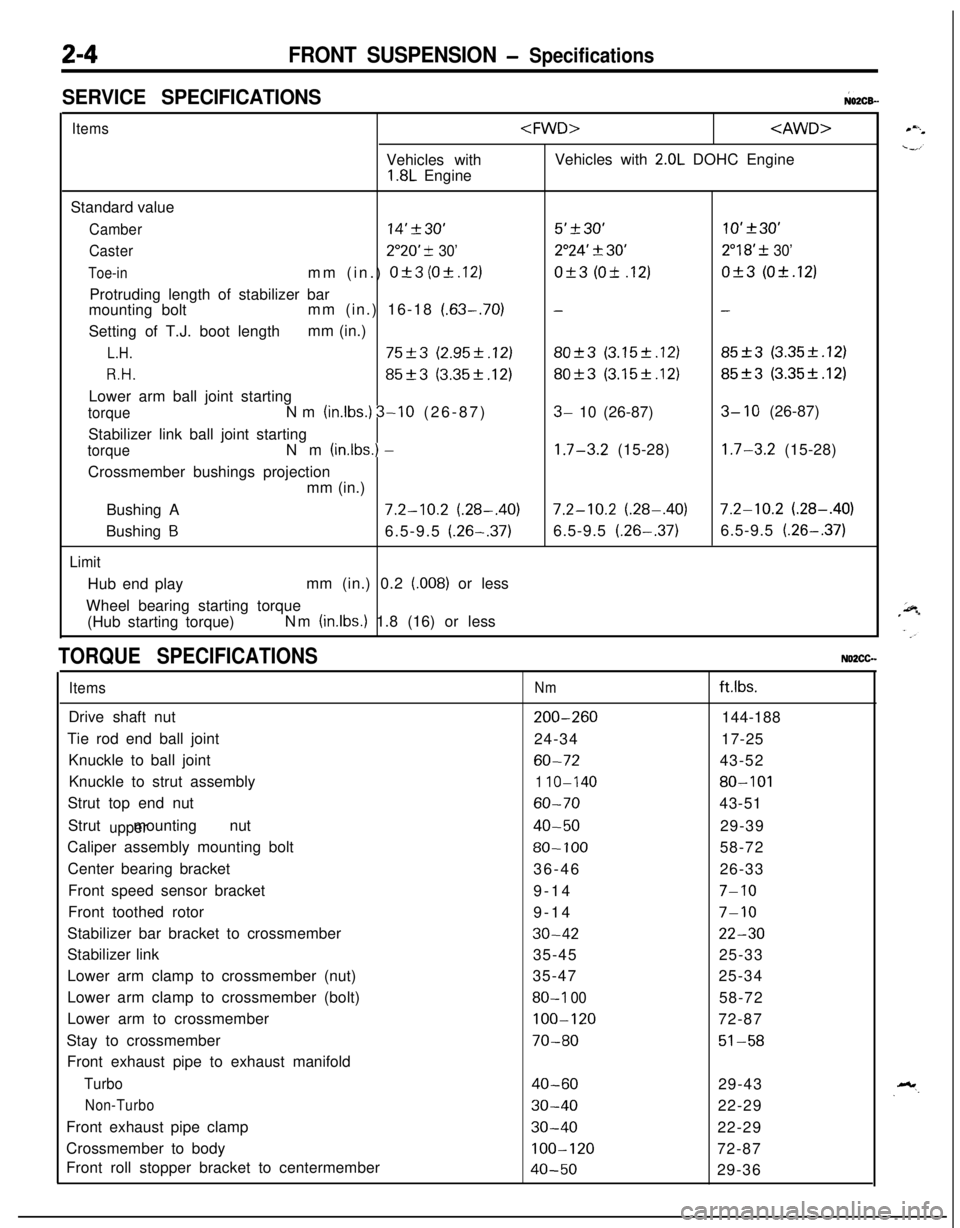
2-4FRONT SUSPENSION - Specifications
SERVICE SPECIFICATIONS;02CB-
ItemsVehicles with
1.8L Engine
2.0L DOHC Engine
Standard value
Camber14’230’5’+30’10’+30’
Caster2”20’ -t 30’2”24’ 3130’2”18’ f 30’
Toe-inmm (in.) Of3 (Ok.12)Of3 (Ok .12)Of3 (Ok.12)
Protruding length of stabilizer bar
mounting boltmm (in.) 16-18
(.63-.70)--Setting of T.J. boot lengthmm (in.)
L.H.75+3 (2.95f.12)80-+3 (3.15f.12)85_+3 (3.35k.12)
R.H.85f3 (3.35k.12)80+3 (3.15k.12)85f3 (3.35f.12)Lower arm ball joint starting
torqueNm (in.lbs.) 3-10 (26-87)3- 10 (26-87)3- 10 (26-87)
Stabilizer link ball joint starting
torqueNm (inlbs.) -1.7-3.2 (15-28)1.7-3.2 (15-28)
Crossmember bushings projection
mm (in.)
Bushing A
7.2-10.2 (.28-.40)7.2-10.2 (.28-.40)7.2-10.2 (.28-.40)
Bushing
B6.5-9.5 (.26-.37)6.5-9.5 (.26-.37)6.5-9.5 (.26-.37)
LimitHub end playmm (in.) 0.2
(.008) or less
Wheel bearing starting torque
(Hub starting torque)Nm
(in.lbs.) 1.8 (16) or less
TORQUE SPECIFICATIONSNO2CG.
ItemsDrive shaft nut
Tie rod end ball joint
Knuckle to ball joint
Knuckle to strut assembly
Strut top end nut
Strut mounting nut
upperCaliper assembly mounting bolt
Center bearing bracket
Front speed sensor bracket
Front toothed rotor
Stabilizer bar bracket to crossmember
Stabilizer link
Lower arm clamp to crossmember (nut)
Lower arm clamp to crossmember (bolt)
Lower arm to crossmember
Stay to crossmember
Front exhaust pipe to exhaust manifold
Turbo
Non-TurboFront exhaust pipe clamp
Crossmember to body
Front roll stopper bracket to centermember
Nmftlbs.
200-260144-188
24-3417-25
60-7243-52
1 IO-14080-101
60-7043-51
40-5029-39
80-10058-72
36-4626-33
9-14
7-109-14
7-10
30-4222-3035-4525-33
35-4725-34
80-I 0058-72
100-12072-87
70-8051-58
40-6029-43
30-4022-29
30-4022-29
100-12072-87
40-5029-36
Page 56 of 1216
2-8FRONT SUSPENSION - Service Adjustment Procedures
SERVICE ADJUSTMENT PROCEDURES
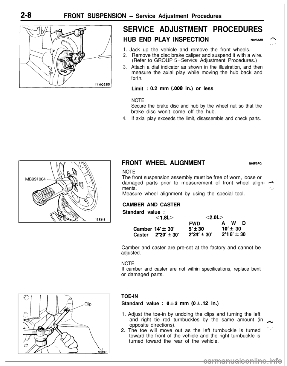
HUB END PLAY INSPECTIONNO2FAAB --- ’
1. Jack up the vehicle and remove the front wheels.
2.Remove the disc brake caliper and suspend it with a wire.
(Refer to GROUP
5-Service Adjustment Procedures.)
3.Attach a dial indicator as shown in the illustration, and thenmeasure the axial play while moving the hub back and
forth.Limit
: 0.2 mm (.008 in.) or less
NOTE
Secure the brake disc and hub by the wheel nut so that thebrake disc won’t come off the hub.
4.If axial play exceeds the limit, disassemble and check parts.
FRONT WHEEL ALIGNMENTNOZFBAQ
NOTEThe front suspension assembly must be free of worn, loose or
damaged parts prior to measurement of front wheel align-
A
ments.--l
Measure wheel alignment by using the special tool.
CAMBER AND CASTER
Standard value
:
<1.8L><2.0L>
FWDAWD
Camber
14’+ 30’5’k3010’f 30
Caster250 + 30’2”24’ + 30’29 8’ f 30Camber and caster are pre-set at the factory and cannot be
adjusted.
NOTE
If camber and caster are not within specifications, replace bentor damaged parts.
TOE-INStandard value
:Of3 mm (Of.12 in.)
1. Adjust the toe-in by undoing the clips and turning the left
and right tie rod turnbuckles by the same amount (in
-opposite directions).
2. The toe will move out as the left turnbuckle is turned
- ,’toward the front of the vehicle and the right turnbuckle is
turned toward the rear of the vehicle.
Page 57 of 1216
FRONT SUSPENSION - service Adjustment Procedures/Hub and Knuckle2-9
3.For each half turn of the left and right tie rods, the toe-in willbe adjusted by 6 mm
(24 in.).
4. After making the adjustments, use a turning radius gauge
to confirm that the steering wheel turning angle is within
the standard value range. (Refer to GROUP 19-Service
Adjustment Procedures.)
WHEEL BEARING ADJUSTMENTN02FCM
Bearing preload is pre-set to the specified value by design andtherefore can not be adjusted.
HUB AND KNUCKLE
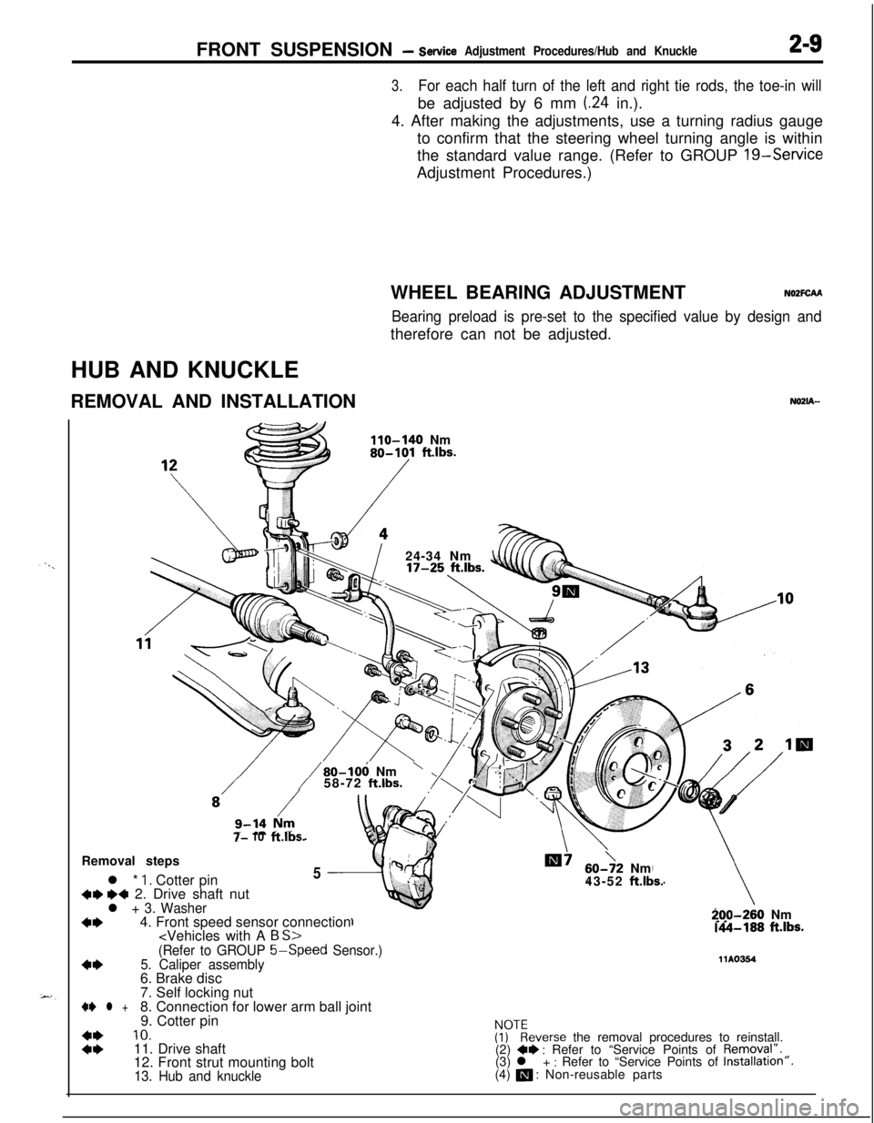
REMOVAL AND INSTALLATION
NOZIA-
110-140 Nm80-101 ft.lbs.
/24-34 Nm
7- 10ft.lbs.
/80-106 Nm’58-72 ft.lbs.Removal steps
l *
1. Cotter pin5
+w ~~ 2. Drive shaft nutl + 3. Washer
+I)4. Front speed sensor connection
60->2 Nm
43-52 ft.lbs.
-70-260 Nm.A-188 ft.lbs.
(Refer to GROUP 5-Speed
Sensor.)
4*5. Caliper assembly11Ams46. Brake disc
7. Self locking nut
+e l +8. Connection for lower arm ball joint
9. Cotter pin
::
10.ivkeverse the removal procedures to reinstall.
11. Drive shaft
(2) +* : Refer to “Service Points of Removql”.
12. Front strut mounting bolt(3) l + : Refer to “Service Points of Installation”.
13. Hub and knuckle(4) a : Non-reusable parts
Page 58 of 1216
z-10FRONT SUSPENSION - Hub and Knuckle
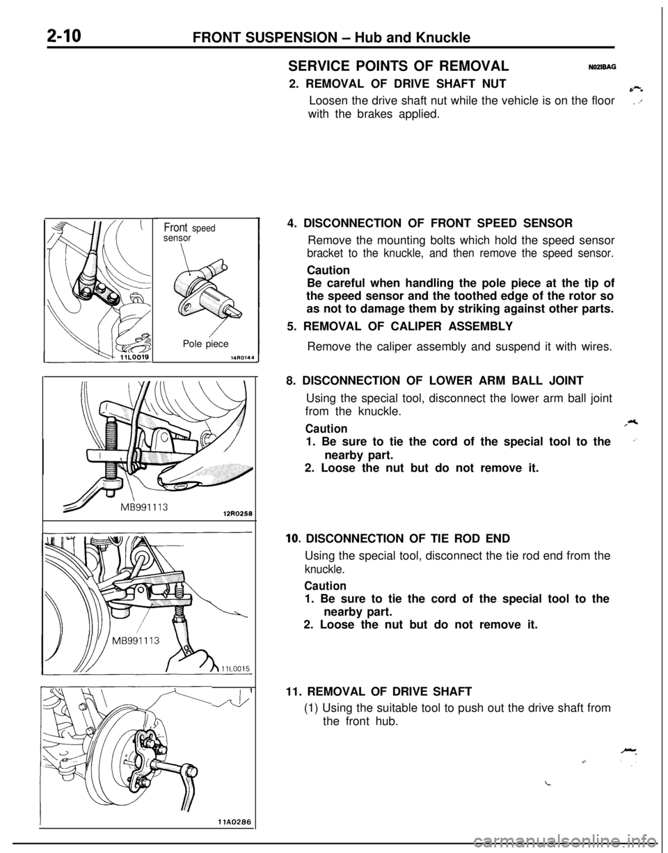
SERVICE POINTS OF REMOVAL
NOZIBAG2. REMOVAL OF DRIVE SHAFT NUT
6-eLoosen the drive shaft nut while the vehicle is on the floor
_ ,’with the brakes applied.
Front speedsensorPole piece
,4mx‘l4
J&14. DISCONNECTION OF FRONT SPEED SENSOR
Remove the mounting bolts which hold the speed sensor
bracket to the knuckle, and then remove the speed sensor.Caution
Be careful when handling the pole piece at the tip of
the speed sensor and the toothed edge of the rotor so
as not to damage them by striking against other parts.
5. REMOVAL OF CALIPER ASSEMBLY
Remove the caliper assembly and suspend it with wires.
8. DISCONNECTION OF LOWER ARM BALL JOINT
Using the special tool, disconnect the lower arm ball joint
from the knuckle.
Caution,*1. Be sure to tie the cord of the special tool to the
1nearby part.
2. Loose the nut but do not remove it.
IO. DISCONNECTION OF TIE ROD END
Using the special tool, disconnect the tie rod end from the
knuckle.
Caution1. Be sure to tie the cord of the special tool to the
nearby part.
2. Loose the nut but do not remove it.
11. REMOVAL OF DRIVE SHAFT
(1) Using the suitable tool to push out the drive shaft from
the front hub.
Page 59 of 1216
FRONT SUSPENSION - Hub and Knuckle2-11Pry bar
Transaxle
llE5&
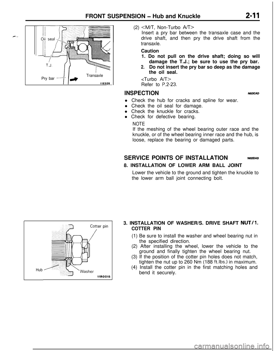
Huber pin(2)
Insert a pry bar between the transaxle case and the
drive shaft, and then pry the drive shaft from the
transaxle.Caution
1. Do not pull on the drive shaft; doing so will
damage the T.J.; be sure to use the pry bar.
2.Do not insert the pry bar so deep as the damage
the oil seal.
P.2-23.
INSPECTIONNO2lCADl Check the hub for cracks and spline for wear.
l Check the oil seal for damage.
l Check the knuckle for cracks.
l Check for defective bearing.
NOTEIf the meshing of the wheel bearing outer race and the
knuckle, or of the wheel bearing inner race and the hub, is
loose, replace the bearing or damaged parts.
SERVICE POINTS OF INSTALLATION
NOZIDAD8. INSTALLATION OF LOWER ARM BALL JOINT
Lower the vehicle to the ground and tighten the knuckle to
the lower arm ball joint connecting bolt.
3. INSTALLATION OF WASHER/S. DRIVE SHAFT
NUT/l.
COTTER PIN(1) Be sure to install the washer and wheel bearing nut in
the specified direction.
(2) After installing the wheel, lower the vehicle to the
ground and finally tighten the wheel bearing nut.
(3) If the position of the cotter pin holes does not match,
tighten the nut up to 260 Nm (188
ftlbs.) in maximum.
(4) Install the cotter pin in the first matching holes and
bend it securely.
Page 60 of 1216
2-12FRONT SUSPENSION - Hub and Knuckle
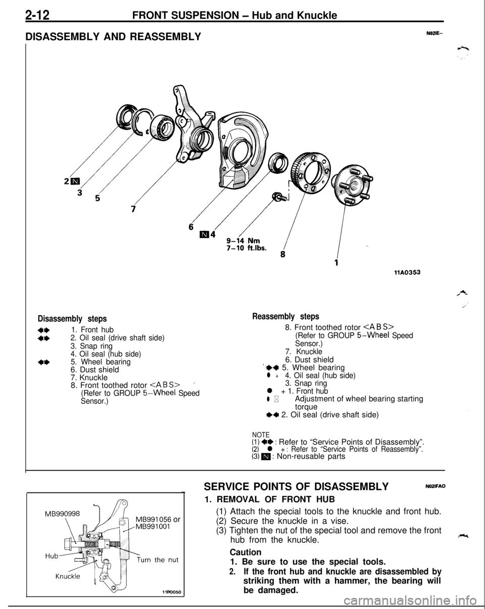
DISASSEMBLY AND REASSEMBLY
N02lE--
Disassembly steps
:t
1. Front hub
2. Oil seal (drive shaft side)
3. Snap ring
4. Oil seal (hub side)
5. Wheel bearing6. Dust shield
7. Knuckle
8. Front toothed rotor
’
(Refer to GROUP 5-Wheel Speed
Sensor.)
llA0353
Reassembly steps8. Front toothed rotor
(Refer to GROUP 5-Wheel Speed
Sensor.)
7. Knuckle6. Dust shield
‘.++ 5. Wheel bearingl +4. Oil seal (hub side)
3. Snap ring
l + 1. Front hub
l *Adjustment of wheel bearing starting
torque
~~ 2. Oil seal (drive shaft side)
NOTE(1) +e : Refer to “Service Points of Disassembly”.(2) l + : Refer to “Service Points of Reassembly”.(3) m : Non-reusable parts
MB991 056 or
11uo050SERVICE POINTS OF DISASSEMBLY
NO2lFAO-1. REMOVAL OF FRONT HUB
(1) Attach the special tools to the knuckle and front hub.
(2) Secure the knuckle in a vise.
(3) Tighten the nut of the special tool and remove the front
hub from the knuckle.
Caution
1. Be sure to use the special tools.
2.If the front hub and knuckle are disassembled bystriking them with a hammer, the bearing will
be damaged.