steering MITSUBISHI ECLIPSE 1991 Owner's Manual
[x] Cancel search | Manufacturer: MITSUBISHI, Model Year: 1991, Model line: ECLIPSE, Model: MITSUBISHI ECLIPSE 1991Pages: 1216, PDF Size: 67.42 MB
Page 101 of 1216
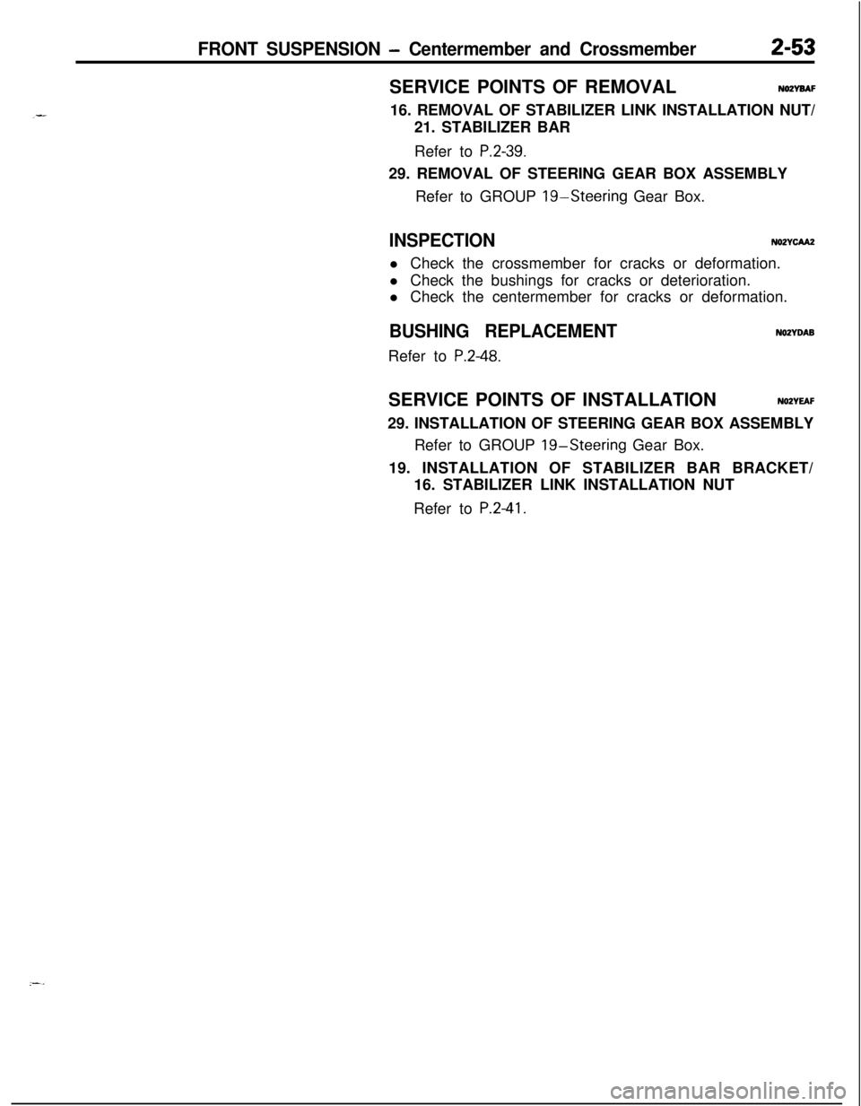
FRONT SUSPENSION - Centermember and Crossmember2-53SERVICE POINTS OF REMOVAL
NOZYBAF16. REMOVAL OF STABILIZER LINK INSTALLATION NUT/
21. STABILIZER BAR
Refer to
P.2-39.29. REMOVAL OF STEERING GEAR BOX ASSEMBLY
Refer to GROUP
19-Steering Gear Box.
INSPECTIONNOZYCAA2l Check the crossmember for cracks or deformation.
l Check the bushings for cracks or deterioration.
l Check the centermember for cracks or deformation.
BUSHING REPLACEMENTRefer to
P.2-48.
NOZYDABSERVICE POINTS OF INSTALLATION
N02YEAF29. INSTALLATION OF STEERING GEAR BOX ASSEMBLY
Refer to GROUP
19-Steering Gear Box.
19. INSTALLATION OF STABILIZER BAR BRACKET/
16. STABILIZER LINK INSTALLATION NUT
Refer to
P.2-41.
Page 149 of 1216
BRAKES - Anti-lock Braking System Troubleshooting5-9
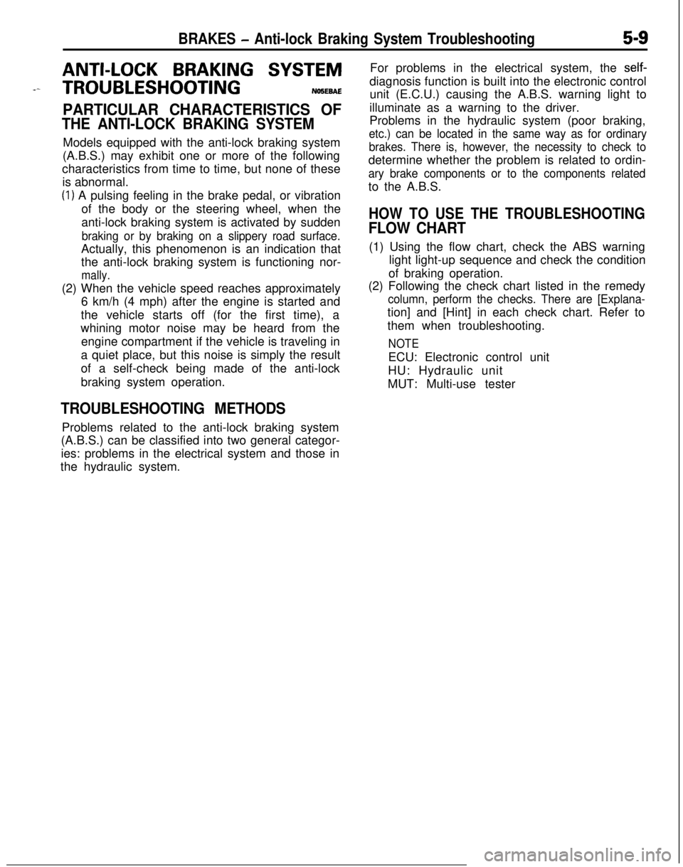
ANTI-LOCK BRAKING SYSTEM
-- TROUBLESHOOTINGNO!JEBAE
PARTICULAR CHARACTERISTICS OF
THE ANTI-LOCK BRAKING SYSTEMModels equipped with the anti-lock braking system
(A.B.S.) may exhibit one or more of the following
characteristics from time to time, but none of these
is abnormal.
(1) A pulsing feeling in the brake pedal, or vibration
of the body or the steering wheel, when the
anti-lock braking system is activated by sudden
braking or by braking on a slippery road surface.Actually, this phenomenon is an indication that
the anti-lock braking system is functioning nor-
mally.(2) When the vehicle speed reaches approximately
6 km/h (4 mph) after the engine is started and
the vehicle starts off (for the first time), a
whining motor noise may be heard from the
engine compartment if the vehicle is traveling in
a quiet place, but this noise is simply the result
of a self-check being made of the anti-lock
braking system operation.
TROUBLESHOOTING METHODSProblems related to the anti-lock braking system
(A.B.S.) can be classified into two general categor-
ies: problems in the electrical system and those in
the hydraulic system.For problems in the electrical system, the
self-diagnosis function is built into the electronic control
unit (E.C.U.) causing the A.B.S. warning light to
illuminate as a warning to the driver.
Problems in the hydraulic system (poor braking,
etc.) can be located in the same way as for ordinary
brakes. There is, however, the necessity to check todetermine whether the problem is related to ordin-
ary brake components or to the components relatedto the A.B.S.
HOW TO USE THE TROUBLESHOOTING
FLOW CHART(1) Using the flow chart, check the ABS warning
light light-up sequence and check the condition
of braking operation.
(2) Following the check chart listed in the remedy
column, perform the checks. There are [Explana-tion] and [Hint] in each check chart. Refer to
them when troubleshooting.
NOTEECU: Electronic control unit
HU: Hydraulic unit
MUT: Multi-use tester
Page 193 of 1216
BRAKES - Brake Pedal5-53
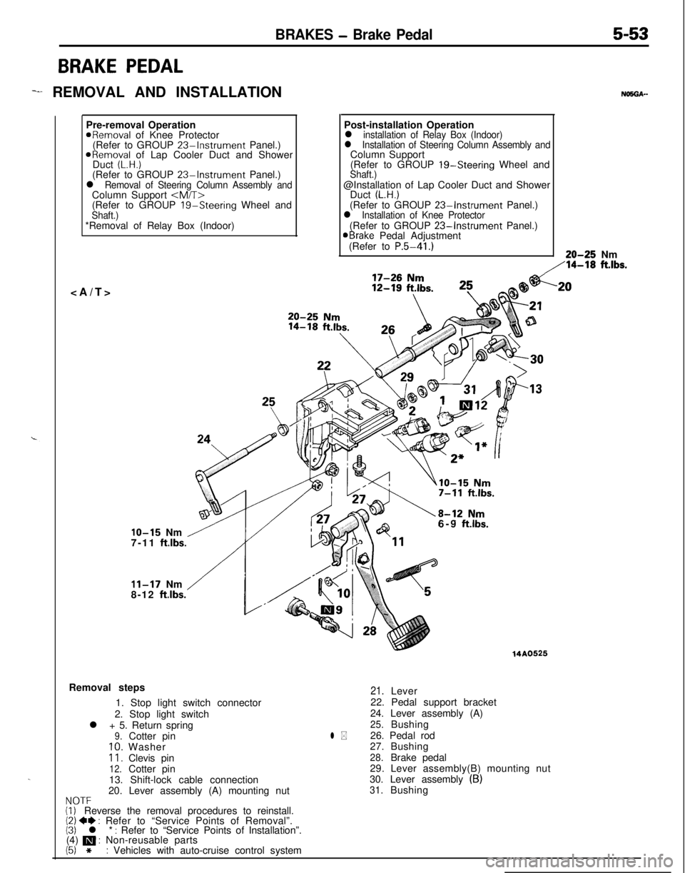
BRAKE PEDAL
-I REMOVAL AND INSTALLATION
.Pre-removal Operation
aRemoval of Knee Protector
(Refer to GROUP 23%Instrument Panel.)
ORemoval of Lap Cooler Duct and Shower
Duct (L.H.)(Refer to GROUP 23-Instrument Panel.)l Removal of Steering Column Assembly andColumn Support
(Refer to GROUP
19-Steering Wheel andShaft.)*Removal of Relay Box (Indoor)
NO5OA--Post-installation Operation
l installation of Relay Box (Indoor)l Installation of Steering Column Assembly andColumn Support
(Refer to GROUP 19-Steering Wheel and
Shaft.)@Installation of Lap Cooler Duct and Shower
Duct
(L.H.)(Refer to GROUP 23-Instrument Panel.)l Installation of Knee Protector(Refer to GROUP 23-Instrument Panel.)aBrake Pedal Adjustment
(Refer to P.5-41.)20-25 Nm
,‘14-18 ft.lbs.
IO-15 Nm /7-11 ft.lbs.
/
11-17 Nm
8-12 ftlbs.6-9
ftlbs.Removal steps
1. Stop light switch connector
2. Stop light switch
l + 5. Return spring
9.Cotter pin10.Washer11.Clevis pin12.Cotter pin
13. Shift-lock cable connection
20. Lever assembly (A) mounting nut
NOTF(i, Reverse the removal procedures to reinstall.(2) 4I) : Refer to “Service Points of Removal”.(3) l * : Refer to “Service Points of Installation”.
(4) m : Non-reusable parts
(5) *: Vehicles with auto-cruise control system
14A0525
l *
21.Lever
22. Pedal support bracket
24. Lever assembly (A)
25.Bushing
26. Pedal rod
27.Bushing
28.Brake pedal
29. Lever assembly(B) mounting nut
30. Lever assembly
(B)31.Bushing
.20
Page 237 of 1216
CLUTCH - Clutch Pedal6-7
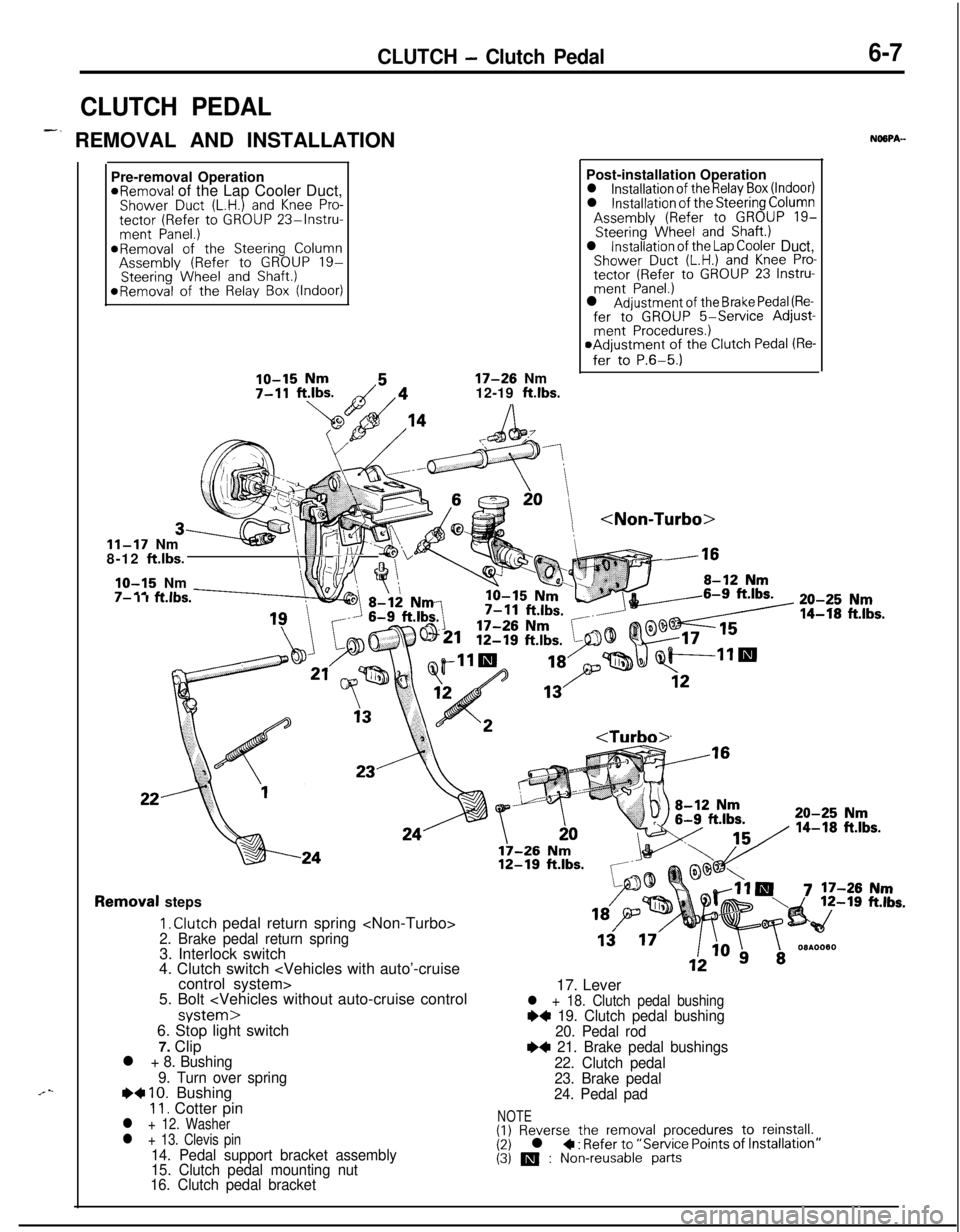
CLUTCH PEDAL
-. REMOVAL AND INSTALLATIONNOSPA-
.“-Pre-removal Operation
*Removal of the Lap Cooler Duct,Shower Duct (L.H.) and Knee Pro-tector (Refer to GROUP 23%lnstru-ment Panel.)*Removal of the Steering ColumnAssembly (Refer to GROUP 19-Steering Wheel and Shaft.)*Removal of the Relay Box (Indoor)
17-26 Nm
12-19 ft.lbs.
11-17 Nm
8-12 ft.lbs.
IO-15 Nm’ tl(i/\:/ Fl/Yv .1-m.---I- I I KIDS.Post-installation Operation
l installation of the Relay Box (Indoor)l installation of the Steering ColumnAssembly (Refer to GROUP 19-Steering Wheel and Shaft.)l installation of the Lap Cooler Duct,Shower Duct (L.H.) and Knee Pro-tector (Refer to GROUP 23 Instru-ment Panel.)l Adjustment of the Brake Pedal (Re-fer to GROUP 5-Service Adjust-ment Procedures.)aAdjustment of the Clutch Pedal (Re-
fer to P.6-5.)
:k -16
20-25 Nm
14-f8 ft.lbs.
Removal steps
I, Clutch pedal return spring
4. Clutch switch
5. Bolt
7. Clip
l + 8. Bushing
9. Turn over spring
e+ IO. Bushing11. Cotter pinl + 12. Washerl + 13. Clevis pin14. Pedal support bracket assembly
15. Clutch pedal mounting nut
16. Clutch pedal bracket17. Lever
l + 18. Clutch pedal bushing~~ 19. Clutch pedal bushing
20. Pedal rod
e+ 21. Brake pedal bushings
22. Clutch pedal
23. Brake pedal
24. Pedal pad
NOTE(1) Reverse the removal procedures to reinstall.(2) l + : Refer to “Service Points of (3) m : Non-reusable parts
Page 251 of 1216
COOLING - Specifications7-3
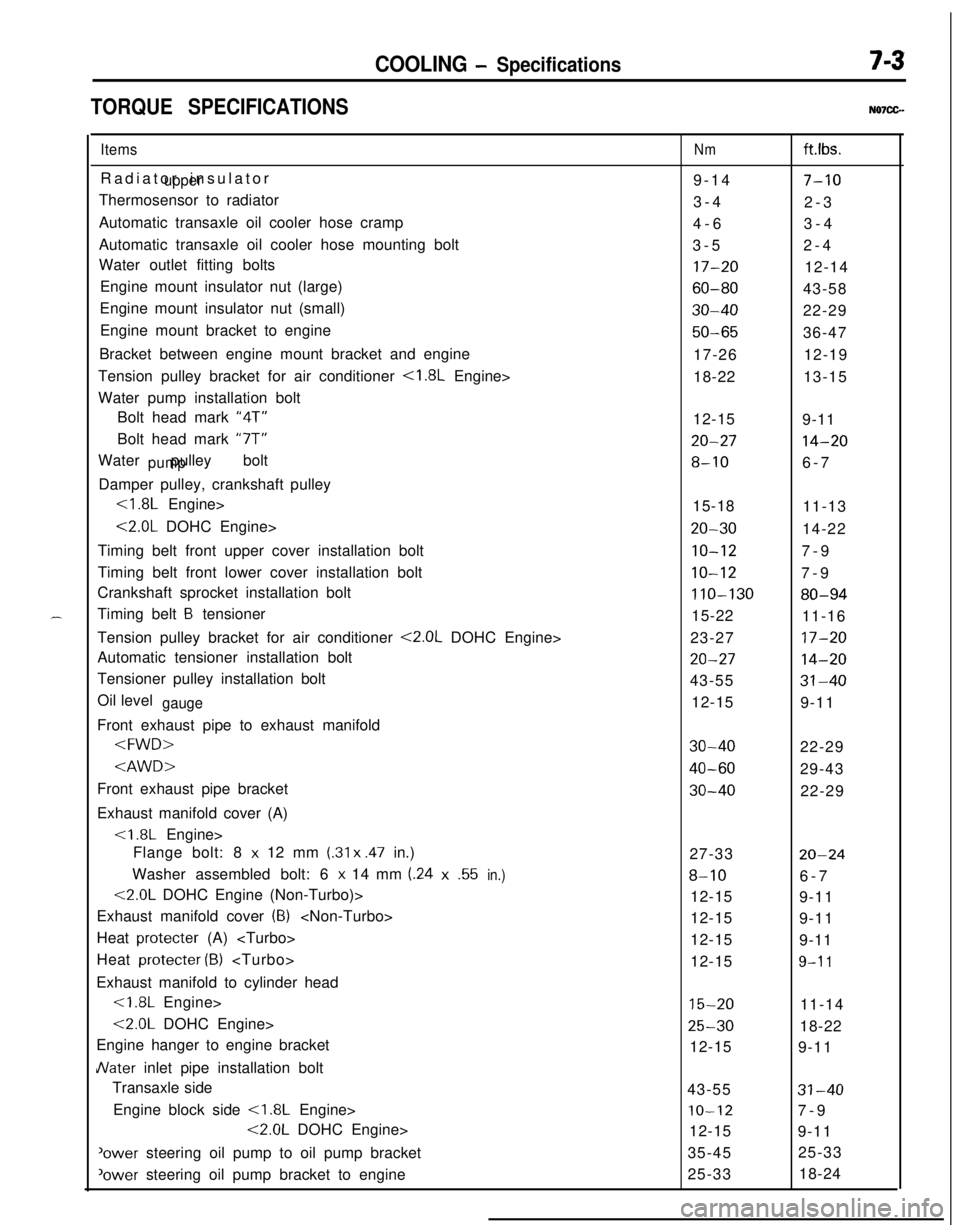
TORQUE SPECIFICATIONSN07CG.
ItemsRadiator insulator
upperThermosensor to radiator
Automatic transaxle oil cooler hose cramp
Automatic transaxle oil cooler hose mounting bolt
Water outlet fitting bolts
Engine mount insulator nut (large)
Engine mount insulator nut (small)
Engine mount bracket to engine
Bracket between engine mount bracket and engine
Tension pulley bracket for air conditioner
<1.8L Engine>
Water pump installation bolt
Bolt head mark “4T”
Bolt head mark “7T”
Water pulley bolt
pumpDamper pulley, crankshaft pulley
<1.8L Engine>
<2.0L DOHC Engine>
Timing belt front upper cover installation bolt
Timing belt front lower cover installation bolt
Crankshaft sprocket installation bolt
Timing belt
B tensioner
Tension pulley bracket for air conditioner
<2.0L DOHC Engine>
Automatic tensioner installation bolt
Tensioner pulley installation bolt
Oil level
gaugeFront exhaust pipe to exhaust manifold
Exhaust manifold cover (A)
Flange bolt: 8
x 12 mm (.31 x .47 in.)
Washer assembled bolt: 6
x 14 mm (.24x.55in.)
<2.0L DOHC Engine (Non-Turbo)>
Exhaust manifold cover
(8)
Heat protecter (A)
Heat protecter
(B)
Exhaust manifold to cylinder head<1.8L Engine>
<2.0L DOHC Engine>
Engine hanger to engine bracket
JVater inlet pipe installation bolt
Transaxle side
Engine block side
<1.8L Engine>
<2.0L DOHC Engine>
'ower steering oil pump to oil pump bracket
‘ower steering oil pump bracket to engine
Nmft.lbs.
9-14
7-103-4
2-3
4-63-4
3-52-4
17-2012-14
60-8043-58
30-4022-29
50-6536-47
17-2612-19
18-2213-15
12-15
9-11
20-2714-20
8-106-7
15-18
11-13
20-3014-22
IO-127-9
10-127-9
110-13080-9415-22
11-16
23-27
17-20
20-2714-2043-55
31-4012-15
9-11
30-4022-29
40-6029-43
30-4022-29
27-33
20-24
8-106-7
12-15
9-11
12-15
9-11
12-15
9-11
12-15
9-l 1
15-2011-14
25-3018-22
12-15
9-11
43-55
31-40
IO-127-9
12-15
9-11
35-4525-33
25-3318-24
Page 265 of 1216
COOLING - Water Pump <1.8L Engine>
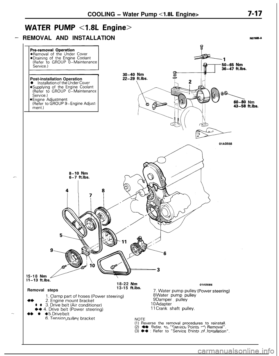
WATER PUMP 4.8L Engine>
7-17
- REMOVAL AND INSTALLATION
c.
-_*Draining of
the Engine Coolant(Refer to GROUP O-Maintenance
Post-installation Operation
l installation of the Under Cover@Supplying of the Engine Coolant(Refer to GROUP O-MaintenanceService.)@Engine Adjustment(RR:; to GROUP g-Engine Adjust-
8-10 Nm6-7 ftlbs.
48NOlMB-A
30-40 Nm
22-2g Fbs.
0
60-80 Nm43-58 ft.lbs.5-18
Nm1-13 ft.lbs.18-22 NmRemoval steps13-15 ft.lbs.
1. Clamp part of hoses (Power steering)4+2. Engine mount bracketl +3. Drive belt (Air conditioner)I)+ 4. Drive belt (Power steering)
4+ l + 5. Drive belt
7. Water pump pulleyWater pump pulleyDamper pullevAdapter. ’Crank shaft pulley.
OlAO566
(Powersteering)
6. Tension tx~llev bra&&I\lnTFr--‘--I -‘--‘.--I.VIL(I) Reverse the removal procedures to reinstall.I?\ CI Refer tn “Smvirr rh:-*- -‘ D---./al”,\-, --. I.VIw, .”..-..,u; r”llllb “I “allI”\(3) +4 : Refer to “Service Points nf Instalk_ - .,.__ -. _.._ .-Jion”.
Page 268 of 1216
7-20COOLING - Water Pump <1.8L Engine>
aWater pump*<
l-----r,//
O-ringWater
pipe
04ROO24Identification
mark04lJoo25Alternater
brace
404uoo22
J
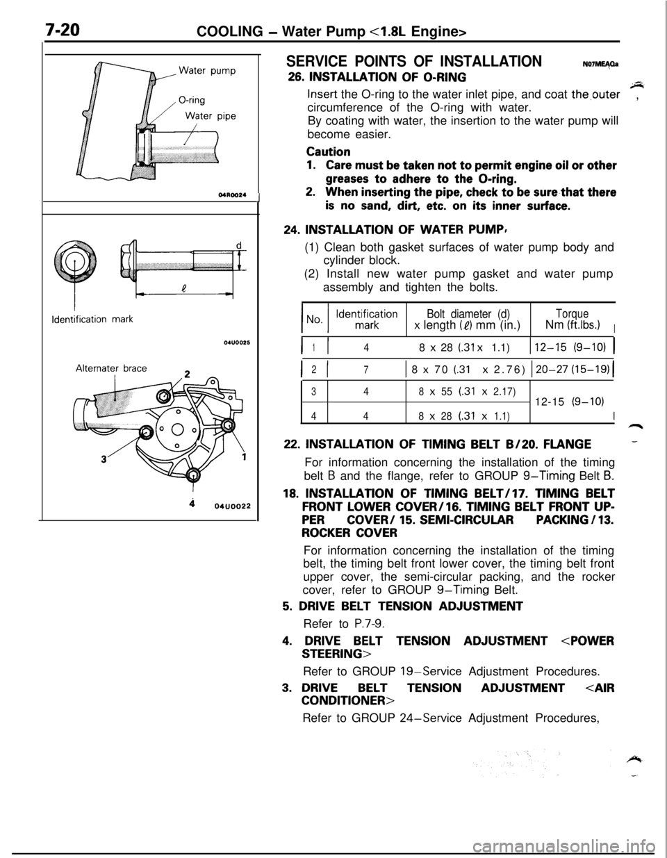
SERVICE POINTS OF INSTALLATIONN07ME40a
26. INSTALLATION OF O-RINGsInsert the O-ring to the water inlet pipe, and coat the,buter
circumference of the O-ring with water.,
By coating with water, the insertion to the water pump will
become easier.
Caution
1.Care must be taken not to permit engine oil or other
greases to adhere to the O-ring.
2.When inserting the pipe, check to be sure,that there
is no sand, dirt, etc. on its inner surface.
24. INSTALLATION OF WATER PUMP,
(1) Clean both gasket surfaces of water pump body and
cylinder block.
(2) Install new water pump gasket and water pump
assembly and tighten the bolts.
Bolt diameter (d)Torque
x length (e) mm (in.)Nm (ftlbs.)I
I I148 x 28 (.31 x 1.1)112-15 (9-10) 1
I I2
71 8 x 70 (.31 x 2.76) 120-27 (15-19)(
348x55(.31x2.17)12-15(9-10)
448x28(.31x1.1)I
22. INSTALLATION OF TIMING BELT B/20. FLANGE-For information concerning the installation of the timing
belt
B and the flange, refer to GROUP g-Timing Belt B.
18. INSTALLATION OF TIMING BELT/l7. TIMING BELT
FRONT LOWER COVER/lG. TIMING BELT FRONT UP-
PERCOVER/ 15. SEMI-CIRCULARPACKING / 13.
ROCKER COVERFor information concerning the installation of the timing
belt, the timing belt front lower cover, the timing belt front
upper cover, the semi-circular packing, and the rocker
cover, refer to GROUP
g-Timing Belt.
5. DRIVE BELT TENSION ADJUSTMENT
Refer to
P.7-9.
4. DRIVE BELT TENSION ADJUSTMENT
Refer to GROUP
19-Service Adjustment Procedures.
3. DRIVEBELTTENSIONADJUSTMENT
Refer to GROUP
24-Service Adjustment Procedures,
Page 269 of 1216
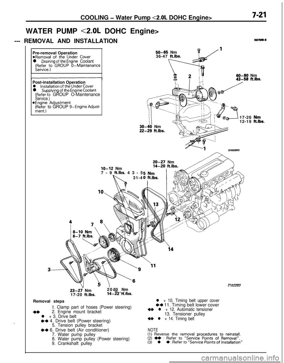
COOLING - Water Pump <2.0L DOHC Engine>7-21WATER PUMP <2.0L DOHC Engine>
--- REMOVAL AND INSTALLATION
No7Ms-B
_Pre-removal Operation
@Removal of the Under Coverl Draining of the Engine Coolant(Refer to GROUP O-MaintenanceService.)
50-65 Nm136-47 ft.lbs.
60-60 Nm
Post-installation Operation
l installation of the Under Coverl supplying of the Engine Coolant(Refer to GROUP O-MaintenanceService.)*Engine Adjustment
(Ri+&; to GROUP g-Engine Adjust-
lo-12 Nm
7-9 ft.lbs. 43-5
31-4
III-40 Nm!-29 ft.lbs.17-26
12-19OlAO560
20-27 Nm14-20 ft.lbs.
23-27 Nm
17-20 ft.lbs.
”20-’ 30 Nm” .““*wY--
-~ . .14-22 ft.ll3s.Removal steps
I. Clamp part of hoses (Power steering)
+*2. Engine mount bracket
l + 3. Drive belte+ 4. Drive belt (Power steering)5. Tension pulley bracket
I)4 6. Drive belt (Air conditioner)7. Water pump pulley
8. Water pump pulley (Power steering)
9. Crankshaft pulley
l + 10. Timing belt upper coverI)4 11. Timing belt lower cover+I) l + 12. Automatic tensioner13. Tensioner pulley
+I) l + 14. Timing belt
NOTE(1) Reverse the removal procedures to reinstall.(2) +e : Refer to “Service Points of Removal”.(3) l 4 : Refer to “Service Points of Installation”
,“k.
Page 272 of 1216
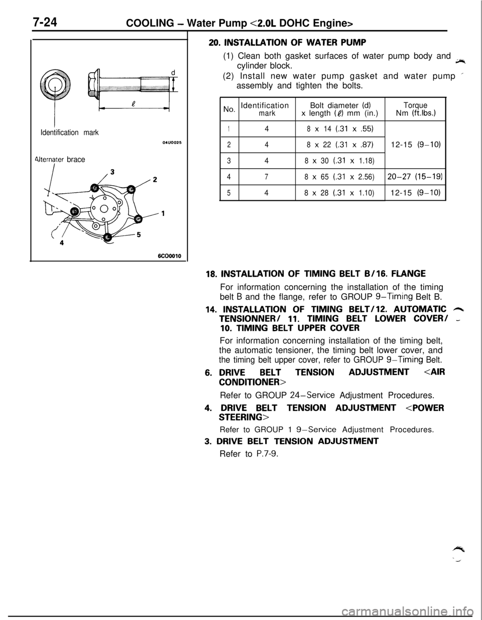
7-24COOLING - Water Pump <2.0L DOHC Engine>
Identification mark
4lternater brace
6COOOlO
20. INSTALLATION OF WATER PUMP
(1) Clean both gasket surfaces of water pump body and
jir,cylinder block.
(2) Install new water pump gasket and water pump ’
assembly and tighten the bolts.
No, IdentificationBolt diameter (d)Torquemarkx length (I?) mm (in.)Nm (ft.lbs.1
148x14(.31x.55)
248x22(.31x.87)12-15(g-10)
348x30(.31x1.18)
4
78x65(.31x2.56)20-27(15-191
548x28(.31x1.10)12-15(g-10)
18. INSTALLATION OF TIMING BELT B/16. FLANGEFor information concerning the installation of the timing
belt
B and the flange, refer to GROUP g-Timing Belt B.
14. INSTALLATION OF TIMING BELT/lZ. AUTOMATIC 6TENSlONNER/
11. TIMING BELT LOWER COVER/ -
10. TIMING BELT UPPER COVERFor information concerning installation of the timing belt,
the automatic tensioner, the timing belt lower cover, and
the timing belt upper cover, refer to GROUP g-Timing Belt.
6. DRIVEBELT TENSIONADJUSTMENT
Refer to GROUP
24-Service Adjustment Procedures.
4. DRIVE BELT TENSION ADJUSTMENT
Refer to GROUP 1
g-Service Adjustment Procedures.
3. DRIVE BELT TENSION ADJUSTMENT
Refer to
P.7-9.
Page 279 of 1216
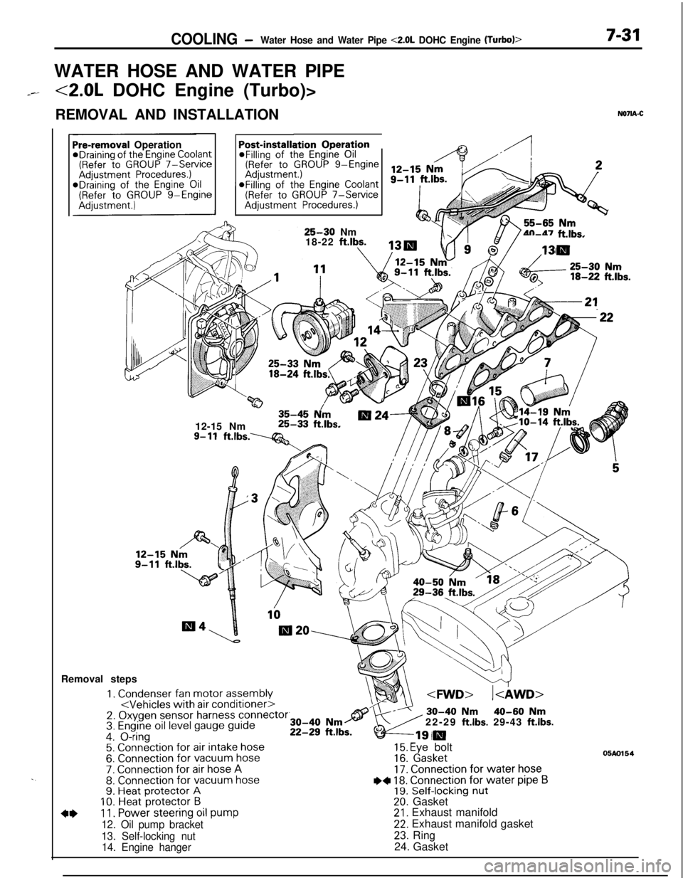
COOLING -Water Hose and Water Pipe <2.0L DOHC Engine (Turbo)>7-31WATER HOSE AND WATER PIPE
7--<2.0L DOHC Engine (Turbo)>
REMOVAL AND INSTALLATION
N071A-C
. .
ation OperationPost-installi@Filling of the Engine Oil(Refer to GROUP g-EngineaFilling of the
Engine Coolant(Refer to GROUP 7-ServiceAdjustment Procedures.)
Pre-removal OperationeDraining of the Engine Coolant(Refer to GROUP 7-ServiceAdjustment Procedures.)*Draining of the Engine Oil(Refer to GROUP g-Engine
25-30 Nm
18-22 ftlbs.4n-47 ft.lbs.
w35-45 N/m12-15 Nm25-33 ft.lbs.
9- 11ft.lbs.----Q&Removal steps
1. Condenser fan motor assembly
4*11. Power steering oil pump
12. Oil pump bracket
13. Self-locking nut
14. Engine hanger22-29
ft.lbs. 29-43 ft.lbs.
15. Eye bolt16. Gasket17. Connection for water hose
I)+ 18. Connection for water pipe B19. Self-locking nut20. Gasket21. Exhaust manifold22. Exhaust manifold gasket
23. Ring
24. Gasket
05m154