steering MITSUBISHI ECLIPSE 1991 Workshop Manual
[x] Cancel search | Manufacturer: MITSUBISHI, Model Year: 1991, Model line: ECLIPSE, Model: MITSUBISHI ECLIPSE 1991Pages: 1216, PDF Size: 67.42 MB
Page 325 of 1216
ENGINE <1.8L Engine> - Timing Belt
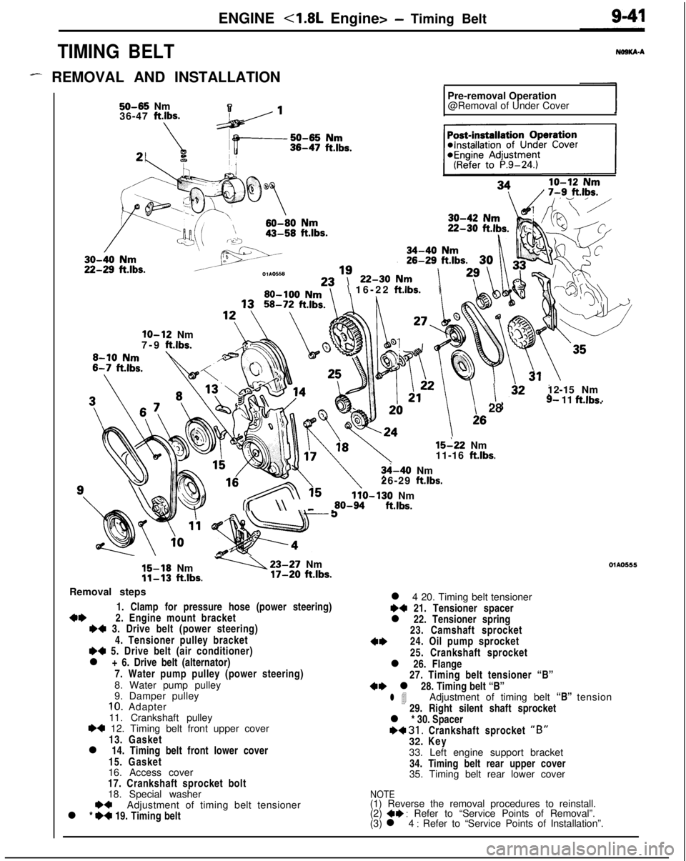
TIMING BELT
- REMOVAL AND INSTALLATION,
50-65 Nm
36-47 ft.lbs.Pre-removal Operation
@Removal of Under Cover
\ 16-22 ftlbs.\
lo-12 Nm
7-9 ft.lbs.
I28
15-22 Nm
11-16 ft.lbs.
3hO Nm
26-29 ft.lbs.
110-130 Nm(( \\ _ 60-94 ftlbs.
15-16 Nm-23-27 Nm
11-13 ft.lbs.17-20 ft.lbs.12-15 Nm
9- 11 ft.lbs.OlAO555
Removal steps
1. Clamp for pressure hose (power steering)
4*2. Engine mount bracketI)* 3. Drive belt (power steering)
4. Tensioner pulley bracket
H 5. Drive belt (air conditioner)
l + 6. Drive belt (alternator)
7. Water pump pulley (power steering)
8. Water pump pulley
9. Damper pulley
10. Adapter
11. Crankshaft pulley
I)4 12. Timing belt front upper cover
13. Gasket
l 14. Timing belt front lower cover
15. Gasket
16. Access cover
17. Crankshaft sprocket bolt
18. Special washer
Adjustment of timing belt tensioner
l *
:: 19. Timing beltl 4 20. Timing belt tensioner
I)+ 21. Tensioner spacer
l 22. Tensioner spring
23. Camshaft sprocket
4*24. Oil pump sprocket
25. Crankshaft sprocket
l 26. Flange
27. Timing belt tensioner “B”
~~ l 28. Timing belt “B”
l 4Adjustment of timing belt “B” tension
29. Right silent shaft sprocket
l * 30. Spacer
~~ 31. Crankshaft sprocket “B”32. Key
33. Left engine support bracket
34. Timing belt rear upper cover
35. Timing belt rear lower cover
NOTE(1) Reverse the removal procedures to reinstall.
(2)
4* : Refer to “Service Points of Removal”.
(3) l 4 : Refer to “Service Points of Installation”.
Page 331 of 1216
ENGINE <1.8L Engine> - Timing Belt9-47
Timing mark
Nut
;olt diameter x lengthim (in.)
6x50(.23 x 1.97)
6
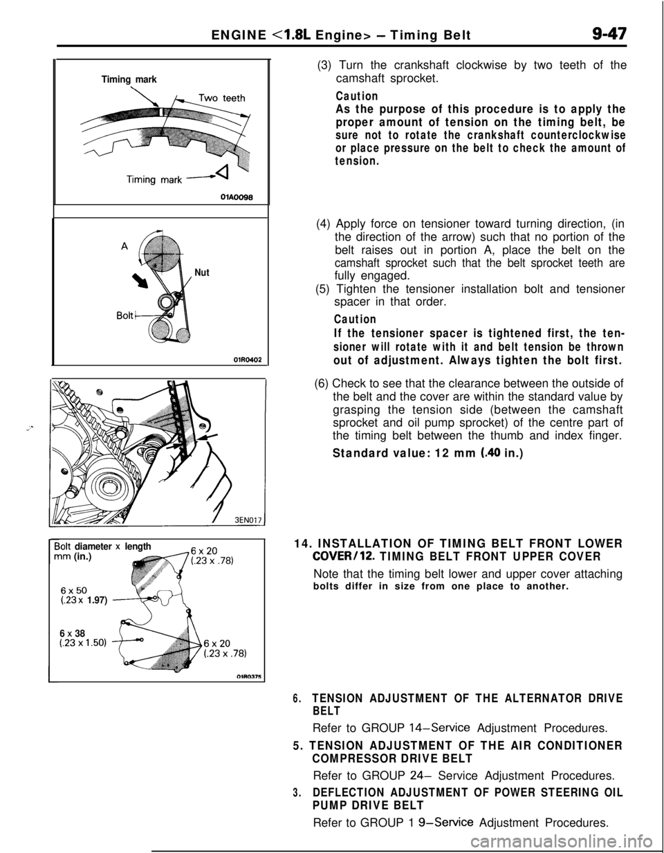
x 38(.23 x 1.50)(3) Turn the crankshaft clockwise by two teeth of the
camshaft sprocket.
Caution
As the purpose of this procedure is to apply the
proper amount of tension on the timing belt, be
sure not to rotate the crankshaft counterclockwise
or place pressure on the belt to check the amount of
tension.(4) Apply force on tensioner toward turning direction, (in
the direction of the arrow) such that no portion of the
belt raises out in portion A, place the belt on the
camshaft sprocket such that the belt sprocket teeth arefully engaged.
(5) Tighten the tensioner installation bolt and tensioner
spacer in that order.
Caution
If the tensioner spacer is tightened first, the ten-
sioner will rotate with it and belt tension be thrown
out of adjustment. Always tighten the bolt first.(6) Check to see that the clearance between the outside of
the belt and the cover are within the standard value by
grasping the tension side (between the camshaft
sprocket and oil pump sprocket) of the centre part of
the timing belt between the thumb and index finger.
Standard value: 12 mm (.40 in.)
14. INSTALLATION OF TIMING BELT FRONT LOWER
COVER/12. TIMING BELT FRONT UPPER COVERNote that the timing belt lower and upper cover attaching
bolts differ in size from one place to another.
6.TENSION ADJUSTMENT OF THE ALTERNATOR DRIVE
BELTRefer to GROUP
14-Service Adjustment Procedures.
5. TENSION ADJUSTMENT OF THE AIR CONDITIONER
COMPRESSOR DRIVE BELTRefer to GROUP
24- Service Adjustment Procedures.
3.DEFLECTION ADJUSTMENT OF POWER STEERING OIL
PUMP DRIVE BELTRefer to GROUP 1
g-Service Adjustment Procedures.
Page 359 of 1216
_-
a--ENGINE
<2.0L DOHC Engine> -Service Adjustment Procedures9-75
JMANIFOLD VACUUM INSPECTION
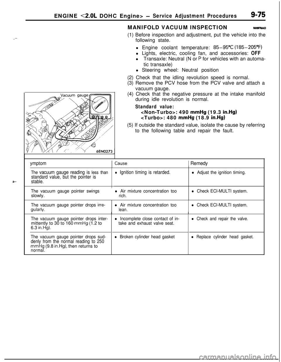
NO9FNAO(1) Before inspection and adjustment, put the vehicle into the
following state.
l Engine coolant temperature:
85-g5”C (185-205°F)
l Lights, electric, cooling fan, and accessories: OFF
lTransaxle: Neutral (N or
P for vehicles with an automa-
tic transaxle)
l Steering wheel: Neutral position
(2) Check that the idling revolution speed is normal.
(3) Remove the PCV hose from the PCV valve and attach a
vacuum gauge.
(4) Check that the negative pressure at the intake manifold
during idle revolution is normal.
Standard value:
mmHg (19.3 in.Hg)
mmHg (18.9 in.Hg)(5) If outside the standard value, isolate the cause by referring
to the following table and repair the fault.
ymptomICause1 Remedy
The vacuum gauge reading is less than
standard value, but the pointer is
stable.
The vacuum gauge pointer swingsslowly.
l Ignition timing is retarded.
l Air mixture concentration too
rich.
l Adjust the ignition timing.
l Check ECI-MULTI system.
The vacuum gauge pointer drops
irre-gularly.l Air mixture concentration too
lean.
l Check ECI-MULTI system.
The vacuum gauge pointer drops inter-mittently to 30 to 160
mmHg (1.2 to
6.3 in.Hg).
The vacuum gauge pointer drops sud-
denly from the normal reading to 250
mmHg (9.8 in.Hg), then returns tonormal.
l Incomplete close contact of in-
take and exhaust valve seat.
l Broken cylinder head gasket
l Check and repair the valve.
l Replace cylinder head gasket.
Page 361 of 1216
ENGINE <2.0L DOHC Engine> - Engine Mounting
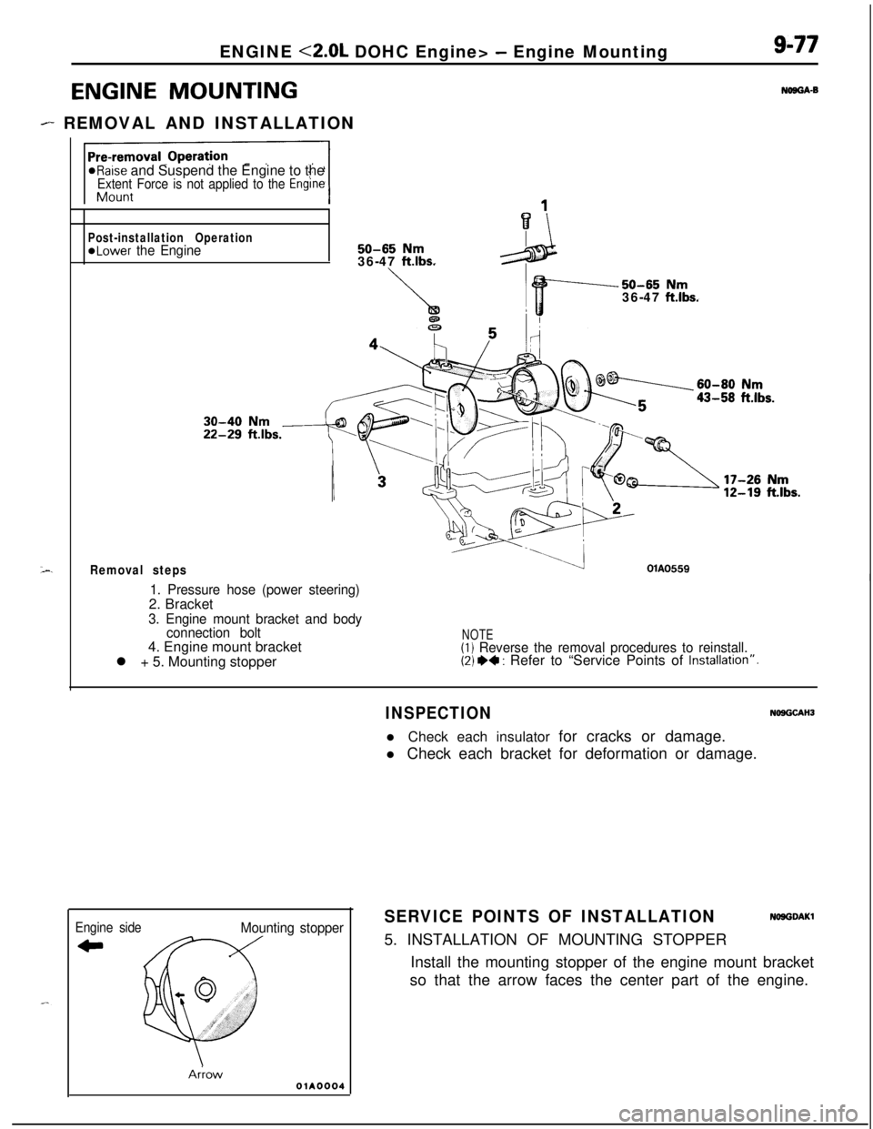
ENGINE MOUNTING
- REMOVAL AND INSTALLATION
9-77
NOBGA-B
*Raise and Suspend the Engine to theExtent Force is not applied to the Engine
Post-installation Operation@Lower the Engine50-65 Nm36-47 ftlbs.
Removal steps
50-65 Nm36-47 ftlbs.
OlAO559I1. Pressure hose (power steering)2. Bracket
3. Engine mount bracket and body
connection bolt4. Engine mount bracket
l + 5. Mounting stopper
NOTE(1) Reverse the removal procedures to reinstall.(2) *+ : Refer to “Service Points of Installatron”.
Engine side
CI
Mounting stopper
AnowOlA0004
INSPECTIONNOSGCAHJl Check each insulator for cracks or damage.
l Check each bracket for deformation or damage.
SERVICE POINTS OF INSTALLATIONNOSGDAKl5. INSTALLATION OF MOUNTING STOPPER
Install the mounting stopper of the engine mount bracket
so that the arrow faces the center part of the engine.
Page 366 of 1216
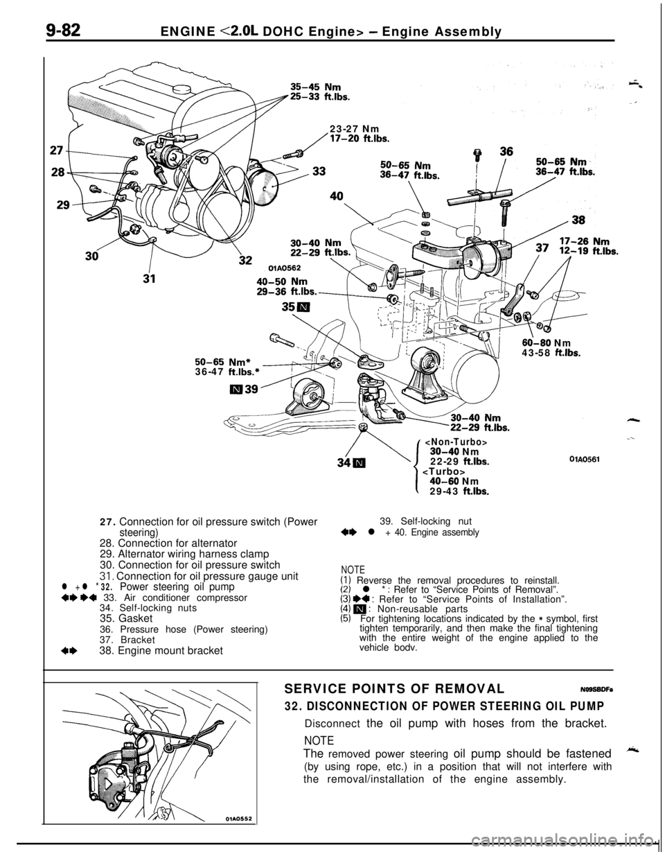
9-82ENGINE <2.0L DOHC Engine> - Engine Assembly
23-27 Nm
/17-20 ftlbs.
60-60 Nm
43-58 ft.lbs.50-65 Nm*36-47 ft.lbs.*27. Connection for oil pressure switch (Power
steering)28. Connection for alternator
29. Alternator wiring harness clamp
30. Connection for oil pressure switch
31, Connection for oil pressure gauge unitl + l * 32.Power steering oil pump+9 ~~ 33. Air conditioner compressor
34. Self-locking nuts
35. Gasket
36. Pressure hose (Power steering)
37. Bracket
4*38. Engine mount bracket
22-29 ftlbs.
.--
OlAO561
1
I40-60 Nm
29-43 ft.lbs.39. Self-locking nut
+e l + 40. Engine assembly
NOTE(I) Reverse the removal procedures to reinstall.(2) l * : Refer to “Service Points of Removal”.(3) I)+ : Refer to “Service Points of Installation”.(4) m : Non-reusable parts(5)For tightening locations indicated by the * symbol, first
tighten temporarily, and then make the final tightening
with the entire weight of the engine applied to the
vehicle bodv.
SERVICE POINTS OF REMOVALNOSSBDFa
32. DISCONNECTION OF POWER STEERING OIL PUMPDisconnect the oil pump with hoses from the bracket.
NOTEThe removed power steering oil pump should be fastened
A(by using rope, etc.) in a position that will not interfere with
the removal/installation of the engine assembly.
Page 367 of 1216
r-.ENGINE <2.0L DOHC Engine>
- Engine AssemblyS-83
OlA0177
-mpp.-/- --OlA0553
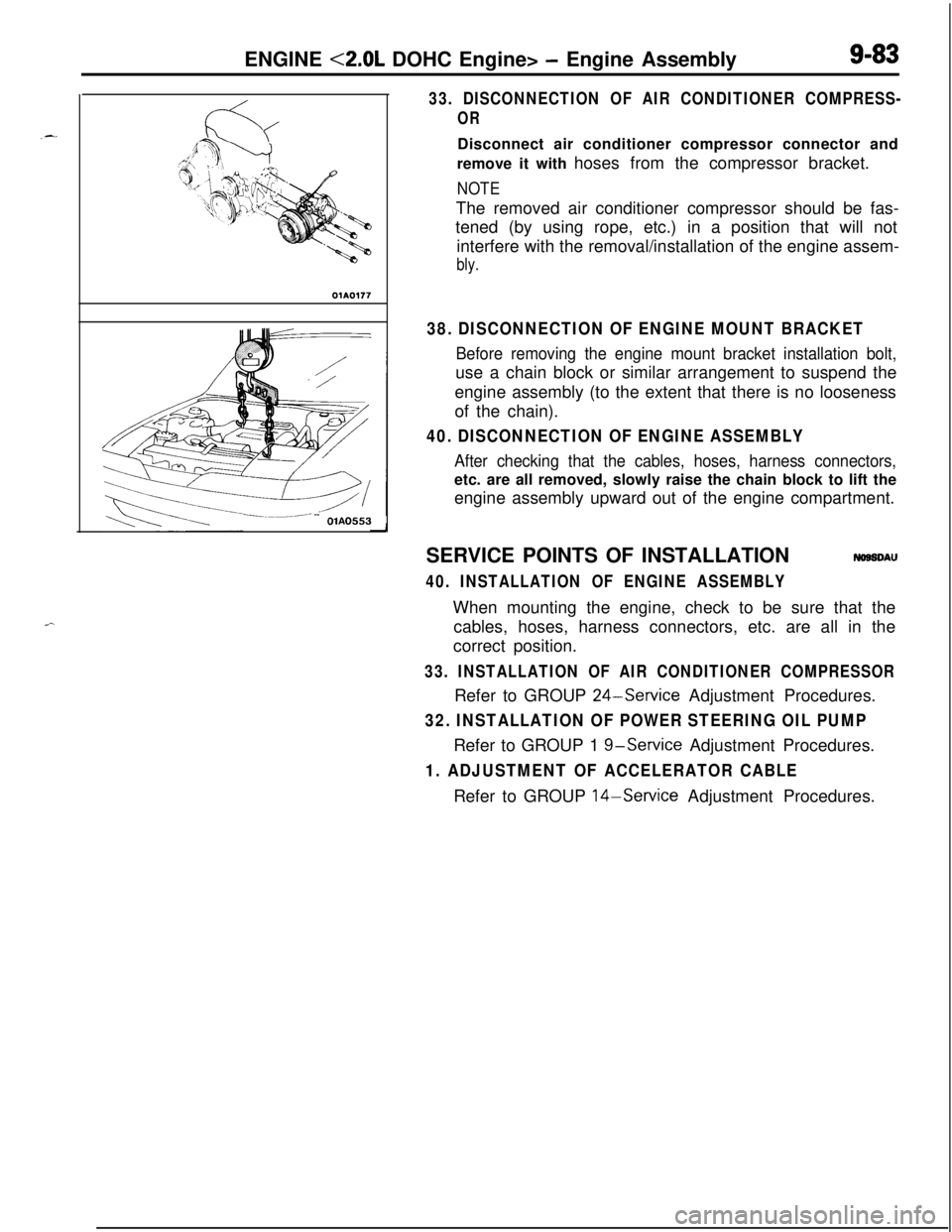
33. DISCONNECTION OF AIR CONDITIONER COMPRESS-
ORDisconnect air conditioner compressor connector and
remove it with hoses from the compressor bracket.
NOTEThe removed air conditioner compressor should be fas-
tened (by using rope, etc.) in a position that will not
interfere with the removal/installation of the engine assem-
bly.
38. DISCONNECTION OF ENGINE MOUNT BRACKET
Before removing the engine mount bracket installation bolt,use a chain block or similar arrangement to suspend the
engine assembly (to the extent that there is no looseness
of the chain).
40. DISCONNECTION OF ENGINE ASSEMBLY
After checking that the cables, hoses, harness connectors,etc. are all removed, slowly raise the chain block to lift the
engine assembly upward out of the engine compartment.
SERVICE POINTS OF INSTALLATION
NOSSDAU
40. INSTALLATION OF ENGINE ASSEMBLYWhen mounting the engine, check to be sure that the
cables, hoses, harness connectors, etc. are all in the
correct position.
33. INSTALLATION OF AIR CONDITIONER COMPRESSORRefer to GROUP
24-Service Adjustment Procedures.
32. INSTALLATION OF POWER STEERING OIL PUMPRefer to GROUP 1
g-service Adjustment Procedures.
1. ADJUSTMENT OF ACCELERATOR CABLERefer to GROUP 14-Service Adjustment Procedures.
Page 379 of 1216
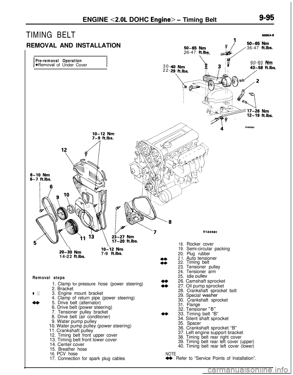
ENGINE <2.0L DOHC Engine> - Timing Belt
TIMING BELT
REMOVAL AND INSTALLATION
I
Pre-removal Operation*Removal of Under Cover
I
50-65 Nm36-47 ft.lbs.
50-65“Nm36-47 ft:lbs.30-60-80
Nm22-20-3\0
Nm14-22 ftlbs.
lo-i2 Nm7-9 ftlbs.
Removal steps
1. Clamp for pressure hose (power steering)2. Bracket
3. Engine mount bracket
4. Clamp of return pipe (power steering)
5. Drive belt (alternator)6. Drive belt (power steering)
7. Tensioner pulley bracket
8. Drive belt (air conditioner)9. Water pump pulley
10. Water pump pulley (power steering)11. Crankshaft pulley12. Timing belt front upper cover13. Timing belt front lower cover
14. Center cover
15. Breather hose16. PCV hose
17. Connection for spark plug cables
l *
4*
NOTE4+ : Refer to “Service Points of Installation”.
WA0581
18.Rocker cover19.Semi-circular packing
20.Plug rubber2 1.Auto tensioner
22.Timing belt
23.Tensioner pulley
24.Tensioner arm
25.Idle oullev26. Camshaft sprocket
27. Oil pump sprocket
28. Crankshaft sprocket bolt
29. Special wastier
30. Crankshaft sprocket
31. Flange32. Tensioner
“B”33. Timing belt “B”
34. Silent shaft sprocket
35. Spacer36. Crankshaft sprocket “B”
37. Left engine support bracket
38. Timing belt rear right cover
39. Timing belt rear left cover (upper)
40. Timing belt rear left cover (lower)
Page 380 of 1216
9-96ENGINE <2.0L DOHC Engine> - Timing Belt
116
/18
Iv- IL 1’11117-9 ftlbs.
\43-49
Nm-_---. . .
30-42 Nm$0
22-30 ftlbs.
\
j2 \ 36
33
15-22 Nm
11-16 ftlbs.
I20-27 Nm\h \
14-20 f&.lbs.110-130 Nm cI,60-94 f
\z/OIAOS83-ama .I~..su--Du Nrnt Ibs .,iJ 36-43 ft.lbs.. .
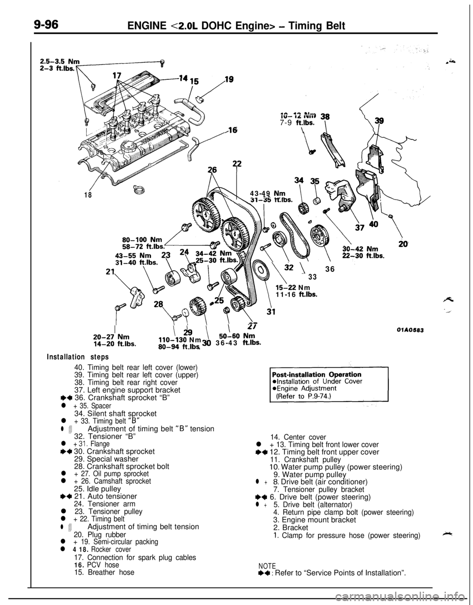
Installation steps
40. Timing belt rear left cover (lower)
39. Timing belt rear left cover (upper)
38. Timing belt rear right cover37. Left engine support bracket
I)+ 36. Crankshaft sprocket “B”
l + 35. Spacer34. Silent shaft sprocket
l + 33. Timing belt “B”
l 4Adjustment of timing belt “B” tension
32. Tensioner “B”
l + 31. Flange++ 30. Crankshaft sprocket
29. Special washer
28. Crankshaft sprocket bolt
l + 27. Oil pump sprocketl + 26. Camshaft sprocket25. Idle pulley
e+ 21. Auto tensioner24. Tensioner arml 23. Tensioner pulleyl + 22. Timing belt
l 4Adjustment of timing belt tension20. Plug rubberl + 19. Semi-circular packingl 4 18. Rocker cover
17. Connection for spark plug cables16. PCV hose15. Breather hose14. Center cover
l + 13. Timing belt front lower covere+ 12. Timing belt front upper cover11. Crankshaft pulley10. Water pump pulley (power steering)
9. Water pump pulley
l +8. Drive belt (air conditioner)7. Tensioner pulley bracketI)+ 6. Drive belt (power steering)l +5. Drive belt (alternator)
4. Return pipe clamp bolt (power steering)3. Engine mount bracket
2. Bracket
1. Clamp for pressure hose (power steering)
NOTE+4 : Refer to “Service Points of Installation”.
Page 392 of 1216
9-l 08ENGINE <2.0L DOHC Engine> - Timing Belt
.hread diameter
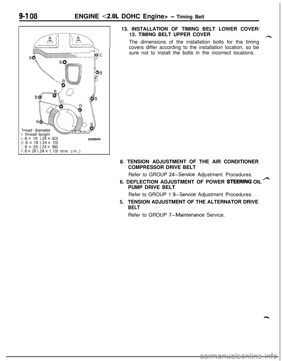
\: 6 x 16(24 x .63)OlAOO45I: 6 x 18 (.24x .70)‘. 6 x 25 (.24 x .98);. 6x28 (.24~1.10) mm (in,)13. INSTALLATION OF TIMING BELT LOWER COVER/
12. TIMING BELT UPPER COVER
F-sThe dimensions of the installation bolts for the timing
covers differ according to the installation location, so be
sure not to install the bolts in the incorrect locations.
8. TENSION ADJUSTMENT OF THE AIR CONDITIONER
COMPRESSOR DRIVE BELT
Refer to GROUP
24-Service Adjustment Procedures.
6. DEFLECTION ADJUSTMENT OF POWER
STEERING OIL .++PUMP DRIVE BELT
Refer to GROUP 1
g-Service Adjustment Procedures.
5.TENSION ADJUSTMENT OF THE ALTERNATOR DRIVE
BELTRefer to GROUP
7-Maintenance Service.
Page 442 of 1216
II-20INTAKE AND EXHAUST - Turbocharger
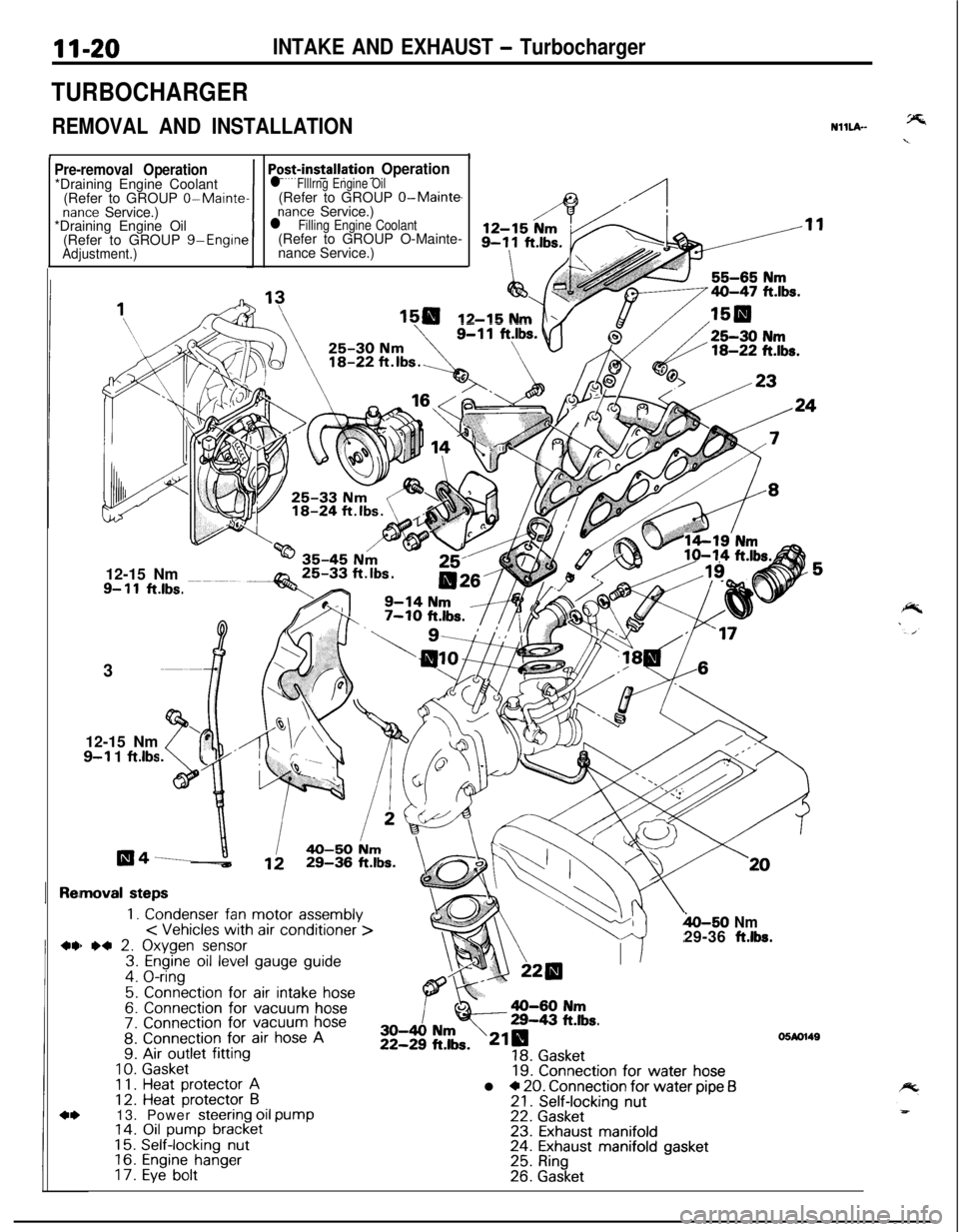
TURBOCHARGER
REMOVAL AND INSTALLATION
II
NHLA-
Pre-removal Operation*Draining Engine Coolant
(Refer to GROUP
0-Maintenance Service.)
*Draining Engine Oil
(Refer to GROUP g-Engine
Adjustment.)1
Po+installation Operationl Flllrng Engine Oil(Refer to GROUP O-Main@
nance Service.)l Filling Engine Coolant(Refer to GROUP O-Mainte-
nance Service.)
12-15 Nm12-15 Nm
9- 11ft.lbs.3
12-15 Nm
9-l 1 ftlbs
moval steps
1. Condenser fan motor assembly< Vehicles with air conditioner >) *4 2. Oxygen sensor3. Engine oil level gauge guide4. O-ring
5. Connection for air intake hose6. Connection for vacuum hose7. Connection for vacuum hose8. Connection for air hose A9. Air outlet fitting
10.Gasket1 1.Heat protector A12. Heat protector B13. Power steering oil pump14. Oil pump bracket15.Self-locking nut16.Engine hanger17.Eye bolt
h-50 Nm29-36 ft.lbs.
19. Connection for water hosel * 20. Connection for water pipe f321. Self-locking nut22. Gasket23. Exhaust manifold24. Exhaust manifold gasket25. Ring26. Gasket
05M1149