steering MITSUBISHI ECLIPSE 1991 User Guide
[x] Cancel search | Manufacturer: MITSUBISHI, Model Year: 1991, Model line: ECLIPSE, Model: MITSUBISHI ECLIPSE 1991Pages: 1216, PDF Size: 67.42 MB
Page 38 of 1216
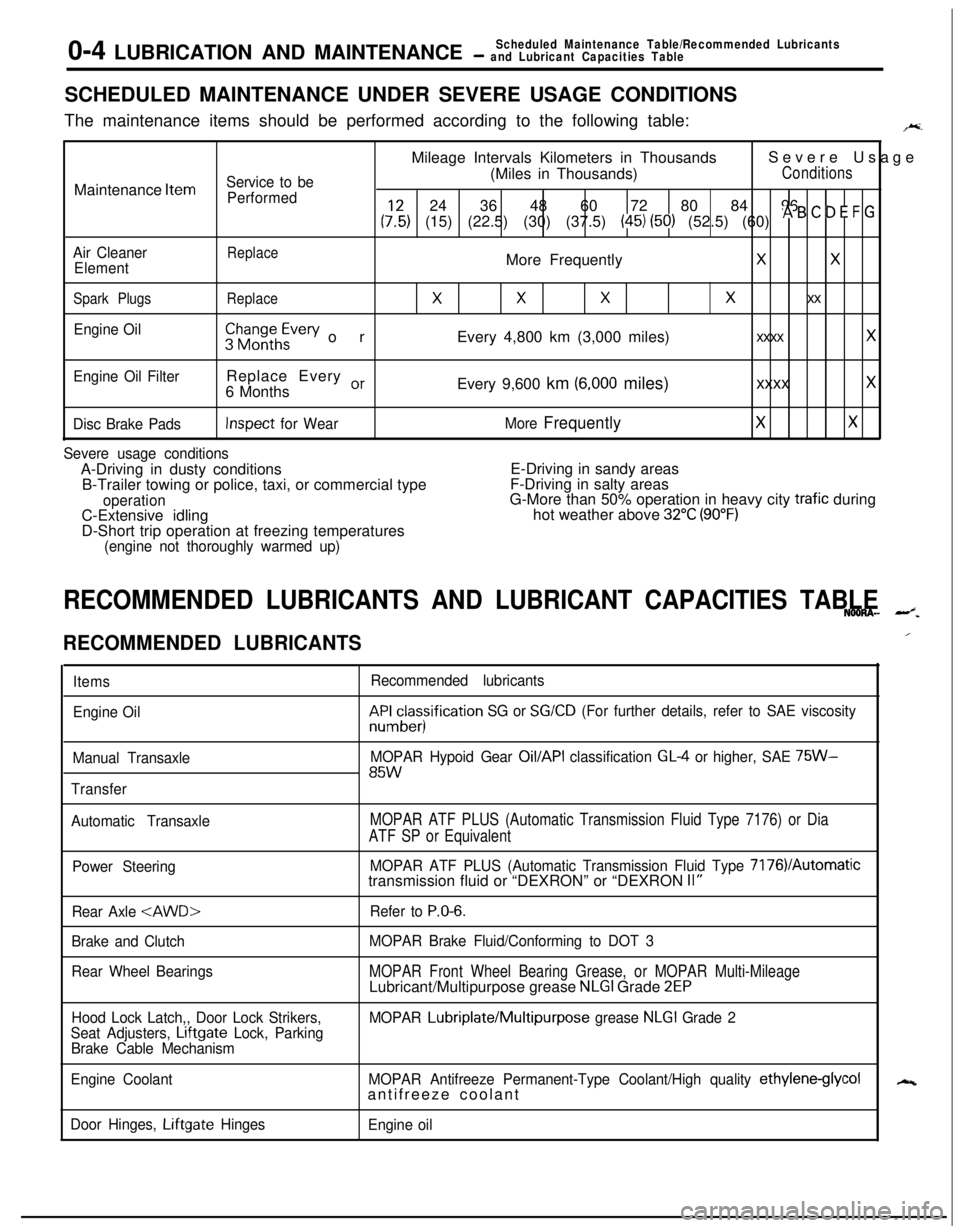
0-4 LUBRICATION AND MAINTENANCEScheduled Maintenance Table/Recommended Lubricants- and Lubricant Capacities TableSCHEDULED MAINTENANCE UNDER SEVERE USAGE CONDITIONS
The maintenance items should be performed according to the following table:
F.Mileage Intervals Kilometers in ThousandsSevere Usage
Service to be(Miles in Thousands)ConditionsMaintenance
Item
Performed24 36 48 60 72 80 84 96
(:,:) (15) (22.5) (30) (37.5) (45) (50) (52.5) (60) * B ’ D E F G
Air CleanerReplaceElementMore FrequentlyXX
Spark PlugsReplace
XXXx xx
Engine Oil$$~~~h~vev orEvery 4,800 km (3,000 miles)xxxx x
Engine Oil FilterReplace Every or6 MonthsEvery 9,600 km (6,000 miles)xxxx x
Disc Brake PadsInspect for WearMore FrequentlyXX
Severe usage conditionsA-Driving in dusty conditionsE-Driving in sandy areas
B-Trailer towing or police, taxi, or commercial typeF-Driving in salty areas
operationG-More than 50% operation in heavy city trafic during
C-Extensive idlinghot weather above 32°C (90°F)D-Short trip operation at freezing temperatures
(engine not thoroughly warmed up)
RECOMMENDED LUBRICANTS AND LUBRICANT CAPACITIES TABLENOONA- --z.
RECOMMENDED LUBRICANTS
Items
Engine Oil
Manual Transaxle
TransferRecommended lubricantskF&cesisification
SG or SG/CD (For further details, refer to SAE viscosity
MOPAR Hypoid Gear
Oil/API classification GL4 or higher, SAE 75W-85W
Automatic TransaxleMOPAR ATF PLUS (Automatic Transmission Fluid Type 7176) or Dia
ATF SP or Equivalent
Power SteeringMOPAR ATF PLUS (Automatic Transmission Fluid Type 7176VAutomatictransmission fluid or “DEXRON” or “DEXRON II”
Rear Axle
Brake and Clutch
Rear Wheel BearingsRefer to
P.O-6.
MOPAR Brake Fluid/Conforming to DOT 3
MOPAR Front Wheel Bearing Grease, or MOPAR Multi-MileageLubricant/Multipurpose grease NLGI Grade 2EP
Hood Lock Latch,, Door Lock Strikers,
Seat Adjusters, Lrftgate Lock, Parking
Brake Cable MechanismMOPAR Lubriplate/Multipurpose grease NLGI Grade 2
Engine CoolantMOPAR Antifreeze Permanent-Type Coolant/High quality
ethylene-glycolantifreeze coolant
Door Hinges, Liftgate Hinges
Engine oil
/
N
Page 39 of 1216
LUBRICATION AND MAINTENANCE - Recommended Lubrie’ntsand Lubrtcant Capacttles Table
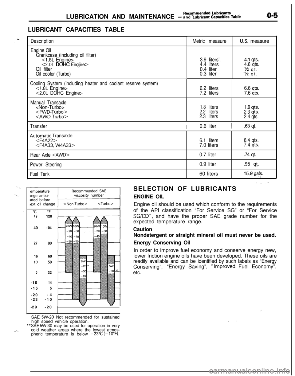
LUBRICANT CAPACITIES TABLE
Description
Engine Oil Engine Oil
Crankcase (including oil filter) Crankcase (including oil filter)
<1.8L Engine><1.8L Engine><2.0L DOHC Engine><2.0L DOHC Enaine>Oil filter Oil filter
Oil cooler (Turbo) Oil cooler (Turbo)
Metric measureU.S. measure
3.9 liters’.4.4 liters
0.4 liter
0.3 liter
4.‘1 qts.4.6 qts.
‘h qt.Y2 qt.
Cooling System (including heater and coolant reserve system)
<2.0L DOHC Engine>6.2 liters
7.2 liters6.6
qts.
7.6 qts.
Manual Transaxle
1.8liters1.9qts.2.2liters2.3qts.
2.3liters
2.4qts.
Transfer
I0.6 literI.63 qt.
Au:oFmqaAtF2pnsaxle
Rear Axle
Power Steering
Fuel Tank
"C“F4912040
104
27
80
1660
1050
032-10
14-15
5-20-4
-23-10
-29-20
6.1 liters6.4 qts.
7.0 liters7.4 qts.
0.7 liter.74 qt.
0.9 liter.95 sf.60 liters
15.9 gal?.
’ ~ “.SELECTION OF LUBRICANTS
ENGINE OIL
Engine oil should be used which conform to the requirements
of the API classification “For Service SG” or “For Service
SGKD”, and have the proper SAE grade number for the
expected temperature range.
Caution
Nondetergent or straight mineral oil must never be used.
Energy Conserving Oil
In order to improve fuel economy and conserve energy new,
lower friction engine oils have been developed. These oils are
readily available and can be identified by such labels as “EnergyConserving”,“Energy Saving”,“Improved Fuel Economy”,
etc.
/”SAE
5W-20 Not recommended for sustained
high speed vehicle operation.**SAE
5W-30 may be used for operation in very
cold weather areas where the lowest atmos-
pheric temperature is below
-23°C (-10°F).
Page 47 of 1216
LUBRICATION AND MAINTENANCE - Maintenance Serviceo-13
OOAOlB6
13.BRAKE HOSES (Check for deteriorati.on or
leaks)NwBBnAs
Inspection of brake hoses and tubing should be included inall brake service operations.
The hoses should be checked for:
1. Correct length, severe surface cracking, pulling, scuf-
fing or worn spots. (If the fabric casing of the hoses is
exposed by cracks of abrasion in the rubber hose cover,
the hoses should be replaced. Eventual deterioration ofhose may occur with possible bursting failure.)
2. Faulty installation, casing twisting or interference with
wheel, tire of chassis.
14.BALL JOINT AND STEERING LINKAGE SEALS
(Inspect for grease leaks and damage)
NWSBJAb1. These components, which are permanently lubricated
at the factory, do not require periodic lubrication.
Damaged seals and boots should be replaced to
prevent leakage or contamination of the grease.
2. Inspect the dust cover and boots for proper sealing,
leakage and damage. Replace them if defective.
15.DRIVE SHAFT BOOTS (Inspect for grease leaksand damage)
NWSBJAc1. These components, which are permanently lubricated
at the factory, do not require periodic lubrication.
Damaged boots should be replaced to prevent leakage
or contamination of the grease.
2. Inspect the boots for proper sealing, leakage and
damage. Replace it if defective.
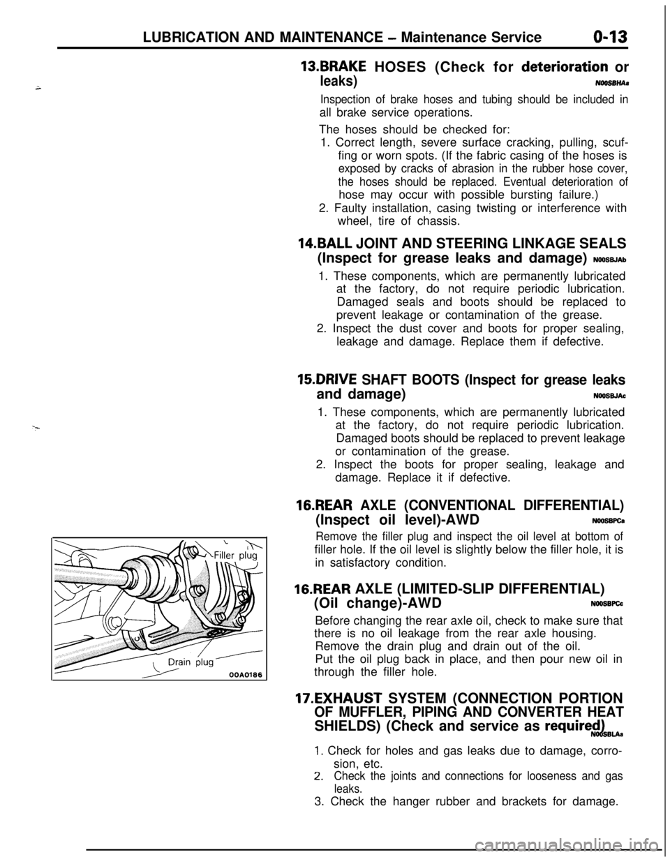
16.REAR AXLE (CONVENTIONAL DIFFERENTIAL)(Inspect oil level)-AWD
NWSBFCa
Remove the filler plug and inspect the oil level at bottom offiller hole. If the oil level is slightly below the filler hole, it is
in satisfactory condition.
16.REAR AXLE (LIMITED-SLIP DIFFERENTIAL)
(Oil change)-AWD
N66SBFCcBefore changing the rear axle oil, check to make sure that
there is no oil leakage from the rear axle housing.
Remove the drain plug and drain out of the oil.
Put the oil plug back in place, and then pour new oil in
through the filler hole.
17.EXHAUST SYSTEM (CONNECTION PORTION
OF MUFFLER, PIPING AND CONVERTER HEATSHIELDS) (Check and service as
require$dBu.
1. Check for holes and gas leaks due to damage, corro-
sion, etc.
2.Check the joints and connections for looseness and gas
leaks.3. Check the hanger rubber and brackets for damage.
Page 53 of 1216
FRONT SUSPENSION - Specifications2-5Items
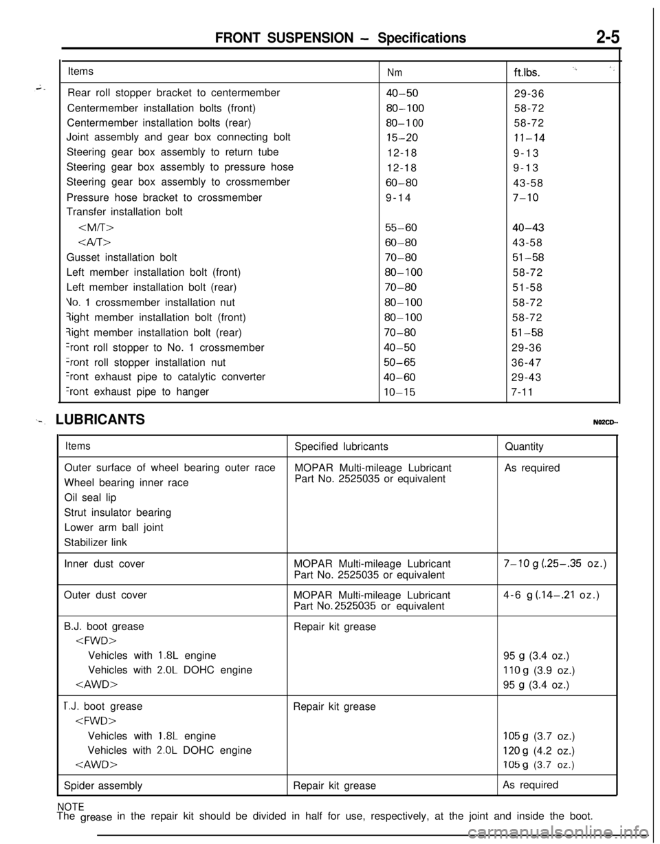
Rear roll stopper bracket to centermember
Centermember installation bolts (front)
Centermember installation bolts (rear)
Joint assembly and gear box connecting bolt
Steering gear box assembly to return tube
Steering gear box assembly to pressure hose
Steering gear box assembly to crossmember
Pressure hose bracket to crossmember
Transfer installation bolt
Nmftlbs. I’, ‘,
40-5029-36
80-10058-72
80-I 0058-72
15-20II-1412-18
9-13
12-189-13
60-8043-58
9-14
7-10
55-6040-43
Gusset installation bolt
70-8051-58Left member installation bolt (front)
80-10058-72
Left member installation bolt (rear)
70-8051-58
Vo. 1 crossmember installation nut80-10058-72qight member installation bolt (front)
80-10058-72?ight member installation bolt (rear)
70-8051-58
+ont roll stopper to No. 1 crossmember40-5029-36
?ont roll stopper installation nut50-6536-47
Iront exhaust pipe to catalytic converter40-6029-43
‘rant exhaust pipe to hangerIO-157-11
‘-. LUBRICANTSNO2CD--
ItemsSpecified lubricantsQuantity
Outer surface of wheel bearing outer race
MOPAR Multi-mileage LubricantAs required
Wheel bearing inner racePart No. 2525035 or equivalent
Oil seal lip
Strut insulator bearing
Lower arm ball joint
Stabilizer link
Inner dust coverMOPAR Multi-mileage Lubricant
Part No. 2525035 or equivalent
7-10 g (.25-.35 oz.)
Outer dust cover
MOPAR Multi-mileage Lubricant
Part
No.2525035 or equivalent4-6
g (.14-.21 oz.)
B.J. boot grease
Repair kit grease
1.8L engine
95 g (3.4 oz.)
Vehicles with
2.0L DOHC engine110 g (3.9 oz.)
T.J. boot grease
Repair kit grease
1.8L engine105 g (3.7 oz.)
Vehicles with
2.0L DOHC engine120 g (4.2 oz.)
Spider assemblyRepair kit greaseAs required
NOTEThe grease in the repair kit should be divided in half for use, respectively, at the joint and inside the boot.
Page 57 of 1216
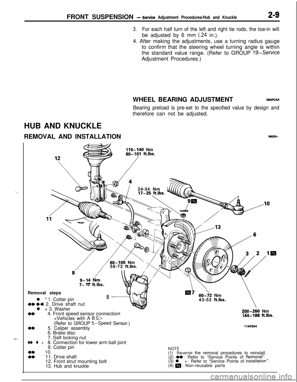
FRONT SUSPENSION - service Adjustment Procedures/Hub and Knuckle2-9
3.For each half turn of the left and right tie rods, the toe-in willbe adjusted by 6 mm
(24 in.).
4. After making the adjustments, use a turning radius gauge
to confirm that the steering wheel turning angle is within
the standard value range. (Refer to GROUP 19-Service
Adjustment Procedures.)
WHEEL BEARING ADJUSTMENTN02FCM
Bearing preload is pre-set to the specified value by design andtherefore can not be adjusted.
HUB AND KNUCKLE
REMOVAL AND INSTALLATION
NOZIA-
110-140 Nm80-101 ft.lbs.
/24-34 Nm
7- 10ft.lbs.
/80-106 Nm’58-72 ft.lbs.Removal steps
l *
1. Cotter pin5
+w ~~ 2. Drive shaft nutl + 3. Washer
+I)4. Front speed sensor connection
60->2 Nm
43-52 ft.lbs.
-70-260 Nm.A-188 ft.lbs.
(Refer to GROUP 5-Speed
Sensor.)
4*5. Caliper assembly11Ams46. Brake disc
7. Self locking nut
+e l +8. Connection for lower arm ball joint
9. Cotter pin
::
10.ivkeverse the removal procedures to reinstall.
11. Drive shaft
(2) +* : Refer to “Service Points of Removql”.
12. Front strut mounting bolt(3) l + : Refer to “Service Points of Installation”.
13. Hub and knuckle(4) a : Non-reusable parts
Page 92 of 1216
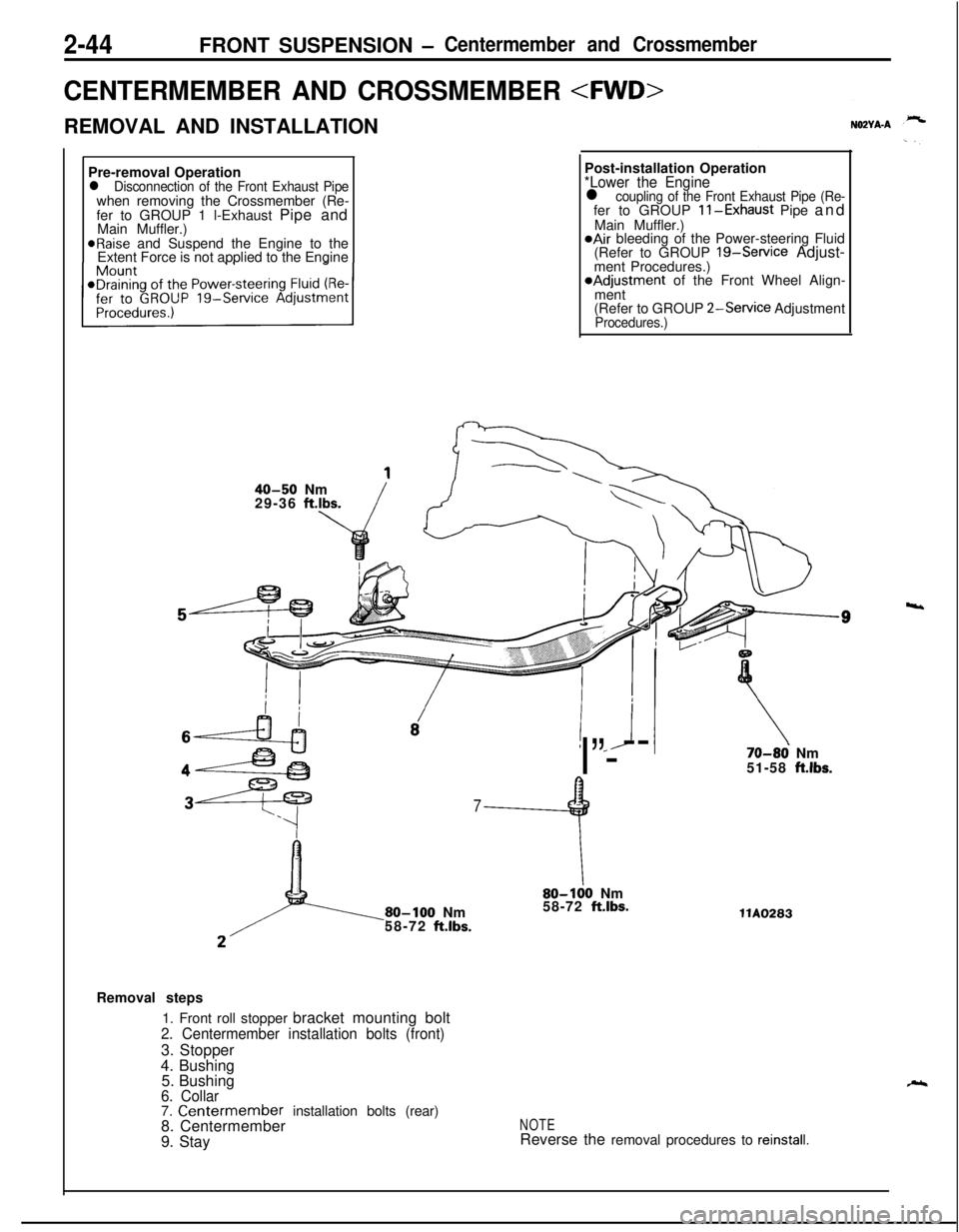
2-44FRONT SUSPENSION -Centermember and Crossmember
CENTERMEMBER AND CROSSMEMBER
REMOVAL AND INSTALLATION
Pre-removal Operation
l Disconnection of the Front Exhaust Pipewhen removing the Crossmember (Re-
fer to GROUP 1 l-Exhaust Pipe and
Main Muffler.)
@Raise and Suspend the Engine to the
Extent Force is not applied to the EnginePost-installation Operation
*Lower the Enginel coupling of the Front Exhaust Pipe (Re-fer to GROUP ll-Exhaust Pipe and
Main Muffler.)
@Air bleeding of the Power-steering Fluid
(Refer to GROUP 19-Service Adjust-
ment Procedures.)*Adjustment of the Front Wheel Align-
ment
(Refer to GROUP
2-Service AdjustmentProcedures.)
40-50 Nm
29-36 ft.lbs.
! *J
I”---
7
9
80-100 Nm
58-72 ft.lbs.
\80-100 Nm
58-72 ft.lbs.
70-86 Nm
51-58 ft.lbs.llA0283
Removal steps
1. Front roll stopper bracket mounting bolt
2. Centermember installation bolts (front)3. Stopper
4. Bushing
5. Bushing
6. Collar7. Centermember installation bolts (rear)
8. Centermember
9. StayNOTEReverse the removal procedures to reinstall.
4
Page 94 of 1216
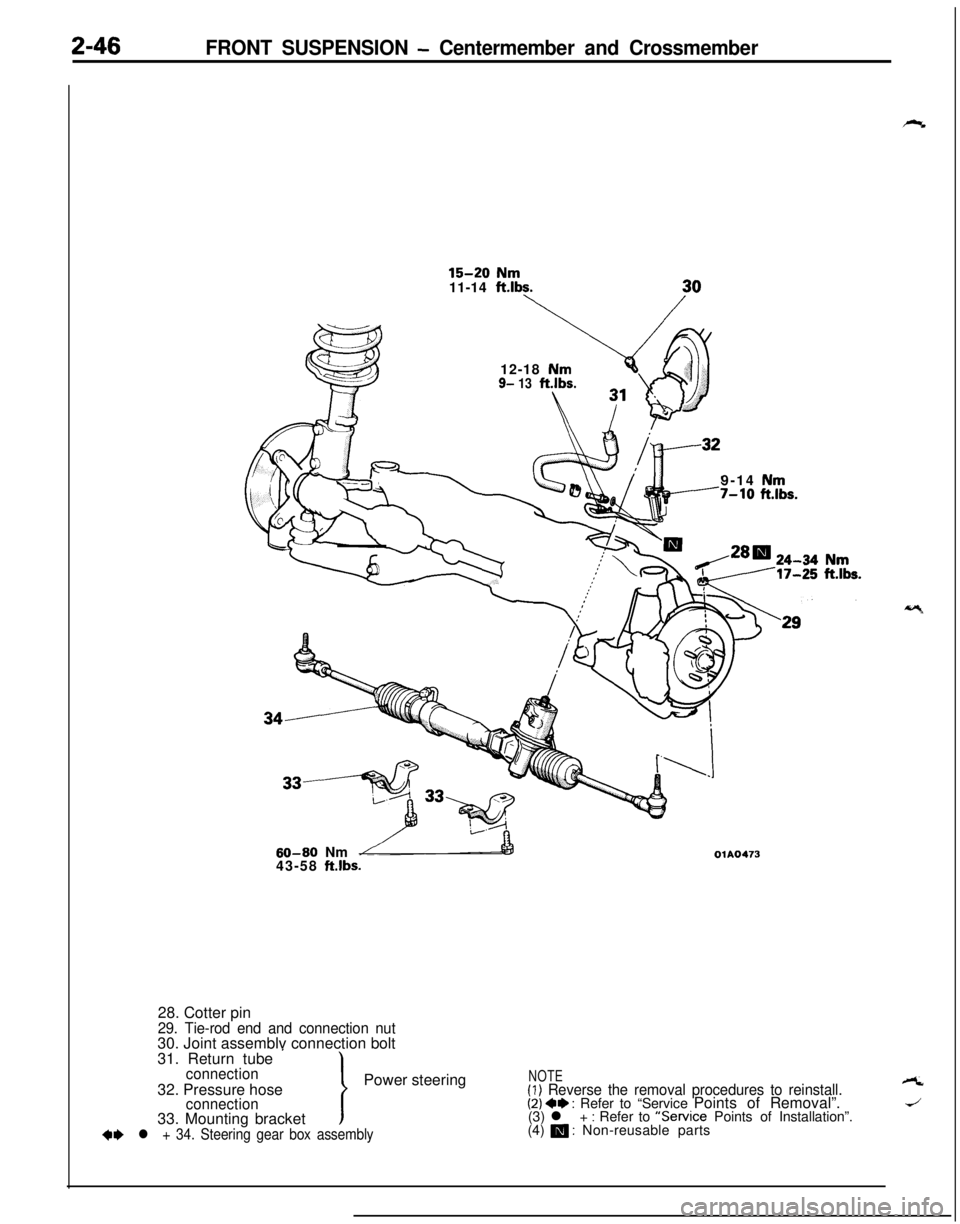
2-46FRONT SUSPENSION - Centermember and Crossmember
15-20 Nm
11-14 ft.lbs.12-18
Nm9- 13ft.lbs.9-14
Nm7-10 ft.lbs.
60-60 Nm
43-58 ft.lbs.OlA047328. Cotter pin
29. Tie-rod end and connection nut30. Joint assemblv connection bolt
31. Return tube
’connectionPower steering
32. Pressure hose
connection33. Mounting bracket
+e l + 34. Steering gear box assembly
NOTE(1) Reverse the removal procedures to reinstall.A
(2) 4+ : Refer to “Service Points of Removal”.J(3) l + : Refer to “Service Points of Installation”.
(4) m : Non-reusable parts
Page 96 of 1216
2-48FRONT SUSPENSION - Centermember and CrossmemberSERVICE POINTS OF REMOVAL
22. REMOVAL OF NUT
Refer to
P.2-39.
N02YBAEa27. REMOVAL OF STABILIZER BAR
Refer to
P.2-39.34. REMOVAL OF STEERING GEAR BOX ASSEMBLY
Refer to GROUP
19-Steering Gear Box.
INSPECTIONN02YCMl
l Check the crossmember for cracks or deformation.
l Check the bushings for cracks or deterioration.
l Check the centermember for cracks or deformation.
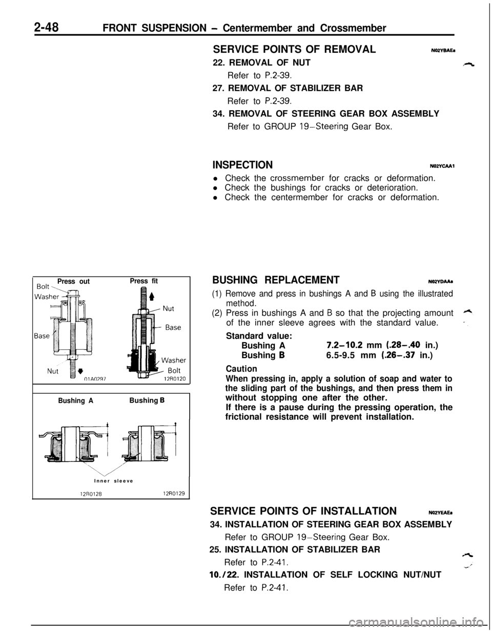
Press outPress fit
Bushing ABushing
BInner sleeve
12R012812RO129
BUSHING REPLACEMENTNOZYDAAa
(1) Remove and press in bushings A and B using the illustrated
method.(2) Press in bushings A and
B so that the projecting amount
of the inner sleeve agrees with the standard value.
Standard value:
Bushing A
7.2-10.2 mm (.28-.40 in.)
Bushing
B6.5-9.5 mm (.26-.37 in.)
Caution
When pressing in, apply a solution of soap and water to
the sliding part of the bushings, and then press them inwithout stopping one after the other.
If there is a pause during the pressing operation, the
frictional resistance will prevent installation.
SERVICE POINTS OF INSTALLATION
NOZYEAEa34. INSTALLATION OF STEERING GEAR BOX ASSEMBLY
Refer to GROUP
19-Steering Gear Box.
25. INSTALLATION OF STABILIZER BAR
Refer to
P.2-41.
10./22. INSTALLATION OF SELF LOCKING NUT/NUT
Refer to
P.2-41.
Page 97 of 1216
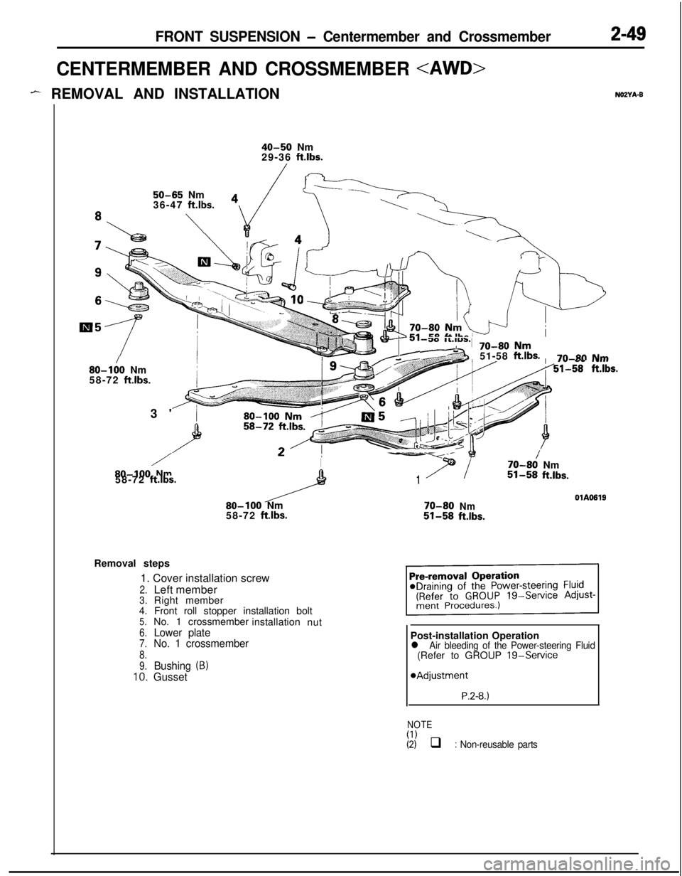
FRONT SUSPENSION - Centermember and Crossmember2-49
CENTERMEMBER AND CROSSMEMBER
- REMOVAL AND INSTALLATIONNOZYA-B
40-50 Nm
29-36 ft.lbs.
50-65 Nm
36-47 ft.lbs.
\
80-I:0 Nm
58-72 ft.lbs.3'
/I-Y--
7t
/70-80Nm80-100 Nm151-58ft.lbs.58-72 ft.lbs.OlA0619
80-100 Nm70-80Nm58-72 ftlbs.51-58ftlbs.
-30 ll.l”S.,
e ~
70-80 Nm51-58
ft.lbs.7n-~0 NmI” .s- .w...51-58 ft.lbs.Removal steps
1. Cover installation screw
2.Left member3.Right member
4. Front roll stopper installation bolt
5.No. 1 crossmember
installation
nut
6.Lower plate7.No. 1 crossmember
8.
9.Bushing (B)10.GussetPost-installation Operation
l Air bleeding of the Power-steering Fluid(Refer to GROUP 19-Service
*Adjustment
P.2-8.)
NOTE
(I)(2) q : Non-reusable parts
Page 99 of 1216
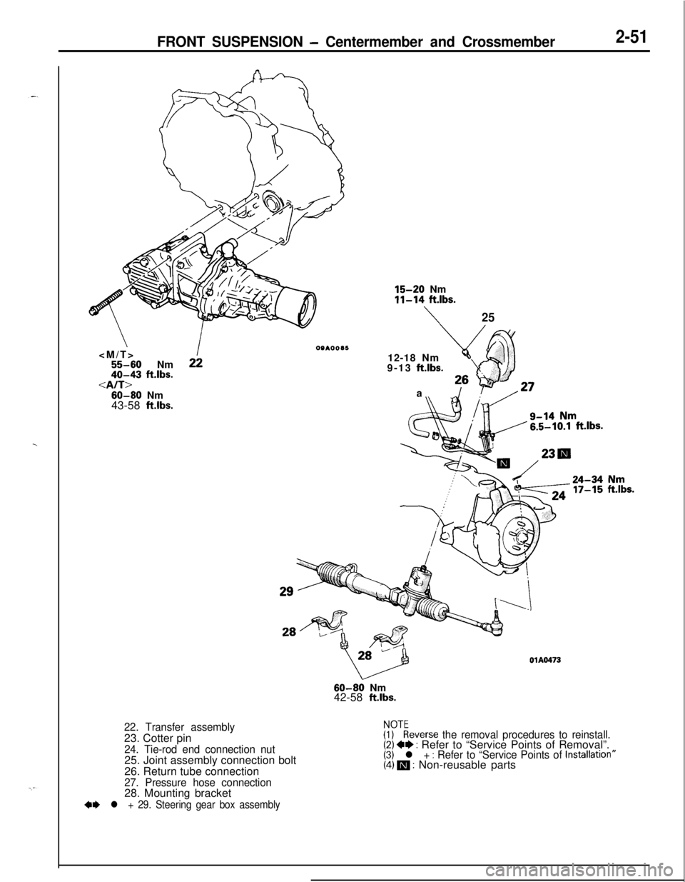
FRONT SUSPENSION - Centermember and Crossmember2-51
\
2240-43 ftlbs.60-80 Nm
43-58
ftlbs.
15-20 Nm11-14 ft.lbs.
\2512-18 Nm
9-13
ft.lbs.a
22. Transfer assembly23. Cotter pin
24. Tie-rod end connection nut25. Joint assembly connection bolt
26. Return tube connection
27. Pressure hose connection28. Mounting bracket
+e l + 29. Steering gear box assembly
OlA047360-80 Nm
42-58
ft.lbs.
Fykeverse the removal procedures to reinstall.(2) ~~ : Refer to “Service Points of Removal”.(3) l + : Refer to “Service Points of lnstallatron”(4) m : Non-reusable parts