engine MITSUBISHI ECLIPSE 1991 Service Manual
[x] Cancel search | Manufacturer: MITSUBISHI, Model Year: 1991, Model line: ECLIPSE, Model: MITSUBISHI ECLIPSE 1991Pages: 1216, PDF Size: 67.42 MB
Page 514 of 1216
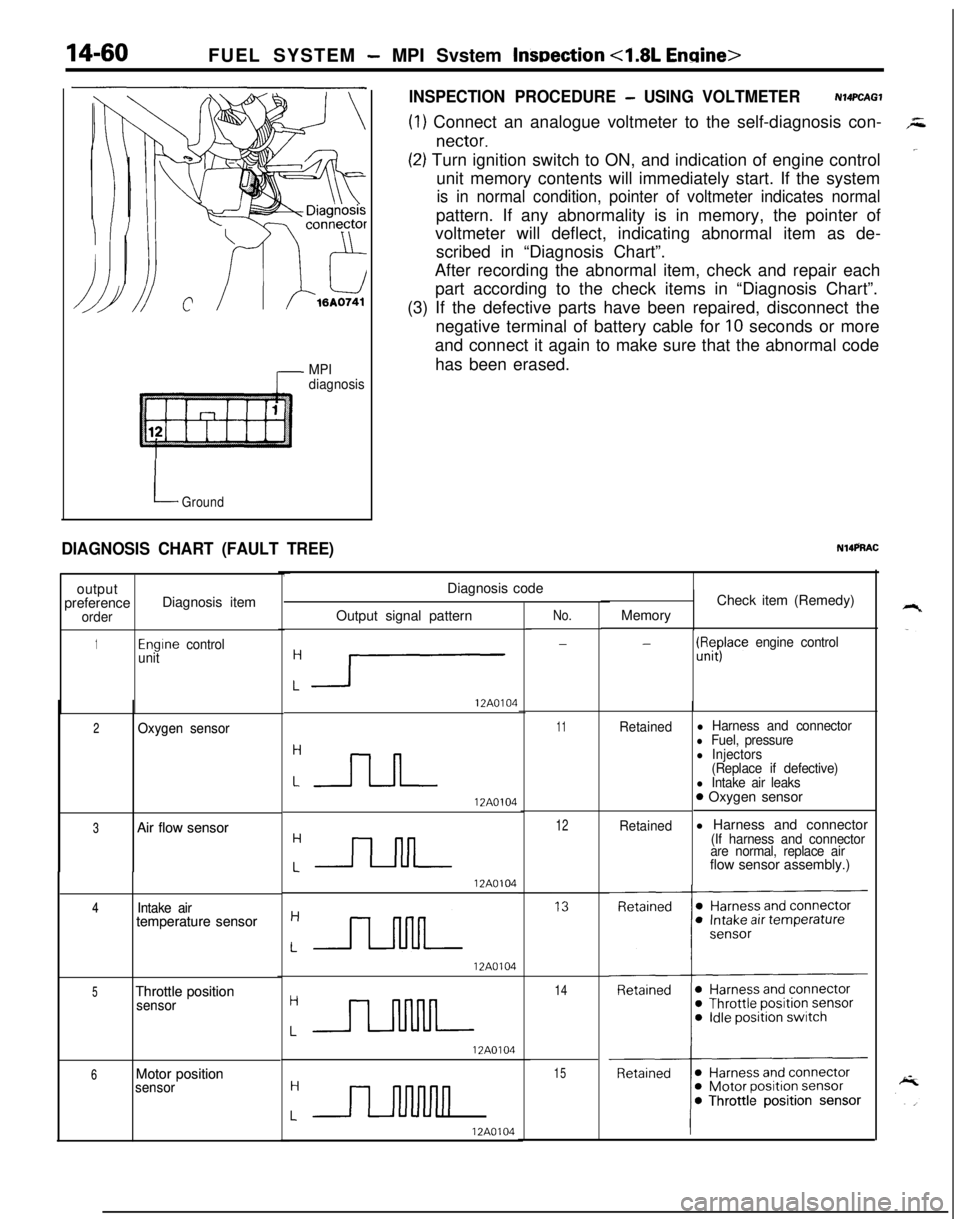
14-60FUEL SYSTEM - MPI Svstem lnwection <1.8L Engine>
7 MPI
diagnosis
LGround
DIAGNOSIS CHART (FAULT TREE)output
preference
orderDiagnosis item
1Engrne control
unit
2 2Oxygen sensor Oxygen sensor
3 3Air flow sensor Air flow sensor
4 4Intake air Intake airtemperature sensor temperature sensor
5 5Throttle position Throttle positionsensor sensor
6 6Motor position Motor positionsensor sensor
INSPECTION PROCEDURE - USING VOLTMETERN14PCAGl
(1) Connect an analogue voltmeter to the self-diagnosis con-,z
nectar.
‘~(2) Turn ignition switch to ON, and indication of engine control
unit memory contents will immediately start. If the system
is in normal condition, pointer of voltmeter indicates normalpattern. If any abnormality is in memory, the pointer of
voltmeter will deflect, indicating abnormal item as de-
scribed in “Diagnosis Chart”.
After recording the abnormal item, check and repair each
part according to the check items in “Diagnosis Chart”.
(3) If the defective parts have been repaired, disconnect the
negative terminal of battery cable for
10 seconds or more
and connect it again to make sure that the abnormal code
has been erased.
N14PRACDiagnosis code
Output signal pattern
:1
12A0104
12A0104
12A0104
12A0104
:JJlJJ--
12A0104
LII
12A0104
No.
-
11Retained
12Retained
14
15MemoryCheck item (Remedy)
-(ll#ace engine control
l Harness and connectorl Fuel, pressurel Injectors
(Replace if defective)
l Intake air leaks0 Oxygen sensor
l Harness and connector
(If harness and connector
are normal, replace airflow sensor assembly.)
Page 515 of 1216
FUEL SYSTEM - MPI System Inspection <1.8L Engine>
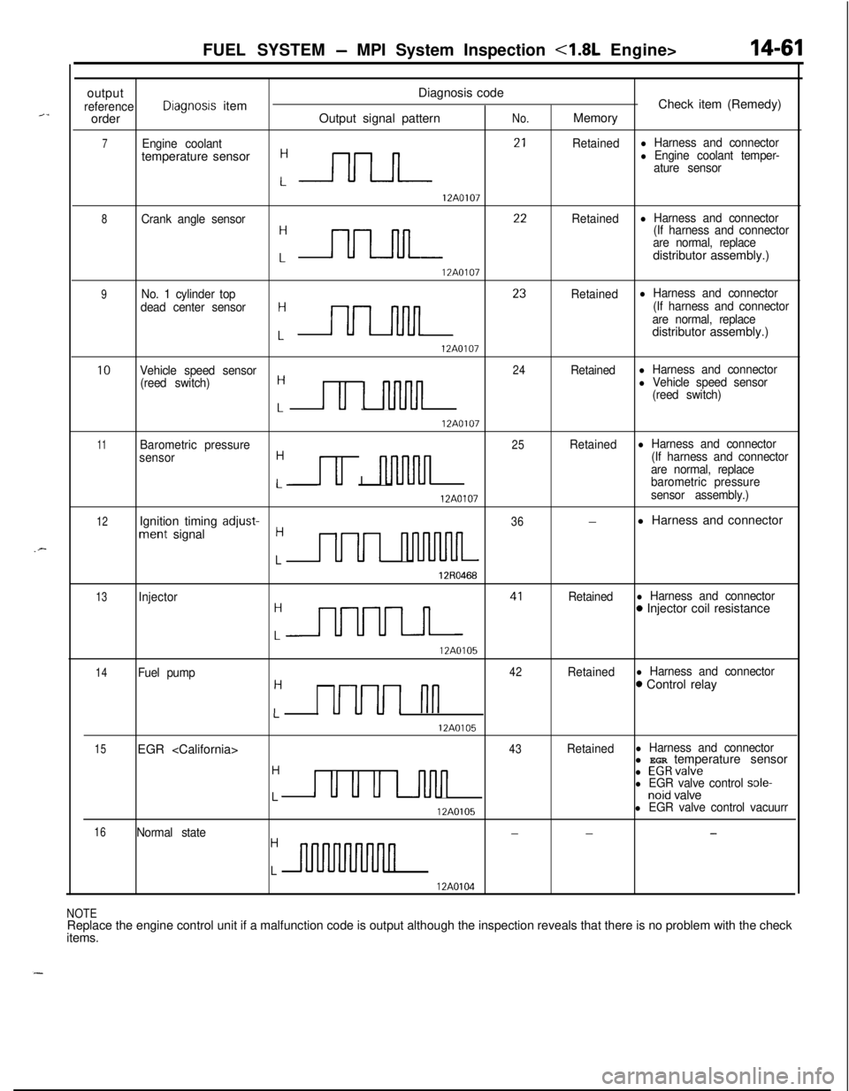
outputDiagnosis code
referenceDiagnosis itemCheck item (Remedy)
orderOutput signal patternNo.Memory
7Engine coolantRetainedl Harness and connectortemperature sensor
:-rlrLn- 2’
l Engine coolant temper-
ature sensor
12A0107
8Crank angle sensor
:nn 22
Retainedl Harness and connector
(If harness and connector
are normal, replacedistributor assembly.)
12A0107
9No. 1 cylinder top
dead center sensorH
Lnn 23
Retainedl Harness and connector
(If harness and connector
are normal, replacedistributor assembly.)
12A0107
10Vehicle speed sensor24Retainedl Harness and connector
(reed switch)H
Lu 1 nnJln
l Vehicle speed sensor
(reed switch)
12A0107
11Barometric pressure25Retainedl Harness and connector
sensorH
u I nl-uvln
(If harness and connector
are normal, replace
Lbarometric pressure
12A0107sensor assembly.)
12Ignition timing adjust-36-l Harness and connectorment signalH
LUUI nluvuuL
12R0468
13Injector
:m 41
Retainedl Harness and connector0 Injector coil resistance
12A0105
14Fuel pump42Retainedl Harness and connectorH0 Control relay
LUUUI nn
12A0105
15EGR
H
u u u u-inn
l EGRvalvel EGR valve control sole-Lnoid valve
12A0105l EGR valve control vacuurr
16Normal state---H
Ln
12A0104
NOTEReplace the engine control unit if a malfunction code is output although the inspection reveals that there is no problem with the check
items.
Page 516 of 1216
14-62FUEL SYSTEM - MPI System Inspection <1.8L Engine>
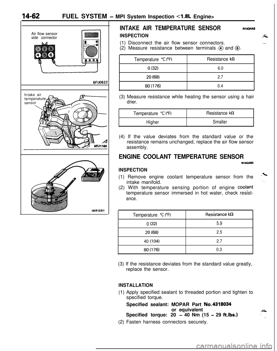
INTAKE AIR TEMPERATURE SENSORNlmNABAir flow sensor
side connectorINSPECTION(1) Disconnect the air flow sensor connectors.
(2) Measure resistance between terminals
@ and @.
6FUO622
Temperature “C PF)Resistance kR
0 (32)6.0
20(68)2.780(176)
0.4(3) Measure resistance while heating the sensor using a hair
drier.
Temperature “C (“F)Resistance kfi
HigherSmaller(4) If the value deviates from the standard value or the
resistance remains unchanged, replace the air flow sensor
assembly.
ENGINE COOLANT TEMPERATURE SENSOR
NWQABE
INSPECTION(1) Remove engine coolant temperature sensor from the
intake manifold.
(2) With temperature sensing portion of engine
cool?nttemperature sensor immersed in hot water, check resist-
ance.16R1251
Temperature “C (“F)Resi’stance kQ
0 (32)5.920(68)
2.5
40 (104)2.7
80(176)0.3(3) If the resistance deviates from the standard value greatly,
replace the sensor.
INSTALLATION(1) Apply specified sealant to threaded portion and tighten to
specified torque.
Specified sealant: MOPAR Part No.4318034
or equivalent
Specified torque: 20
- 40 Nm (15 - 29 ftlbs.)(2) Fasten harness connectors securely.
Page 517 of 1216
FUEL SYSTEM - MPI Svstem Inspection <1.8L Engine>18-63
Throttle position sensor
Groundoutput
Sensorpower
SUPPlY(5V)
1 FUO507
6FU1244Motor
Dosition sensor connector
(motor ‘side, front view)
T
6FU1247Motor position sensor
connector(motor side, front view)
6FU1252
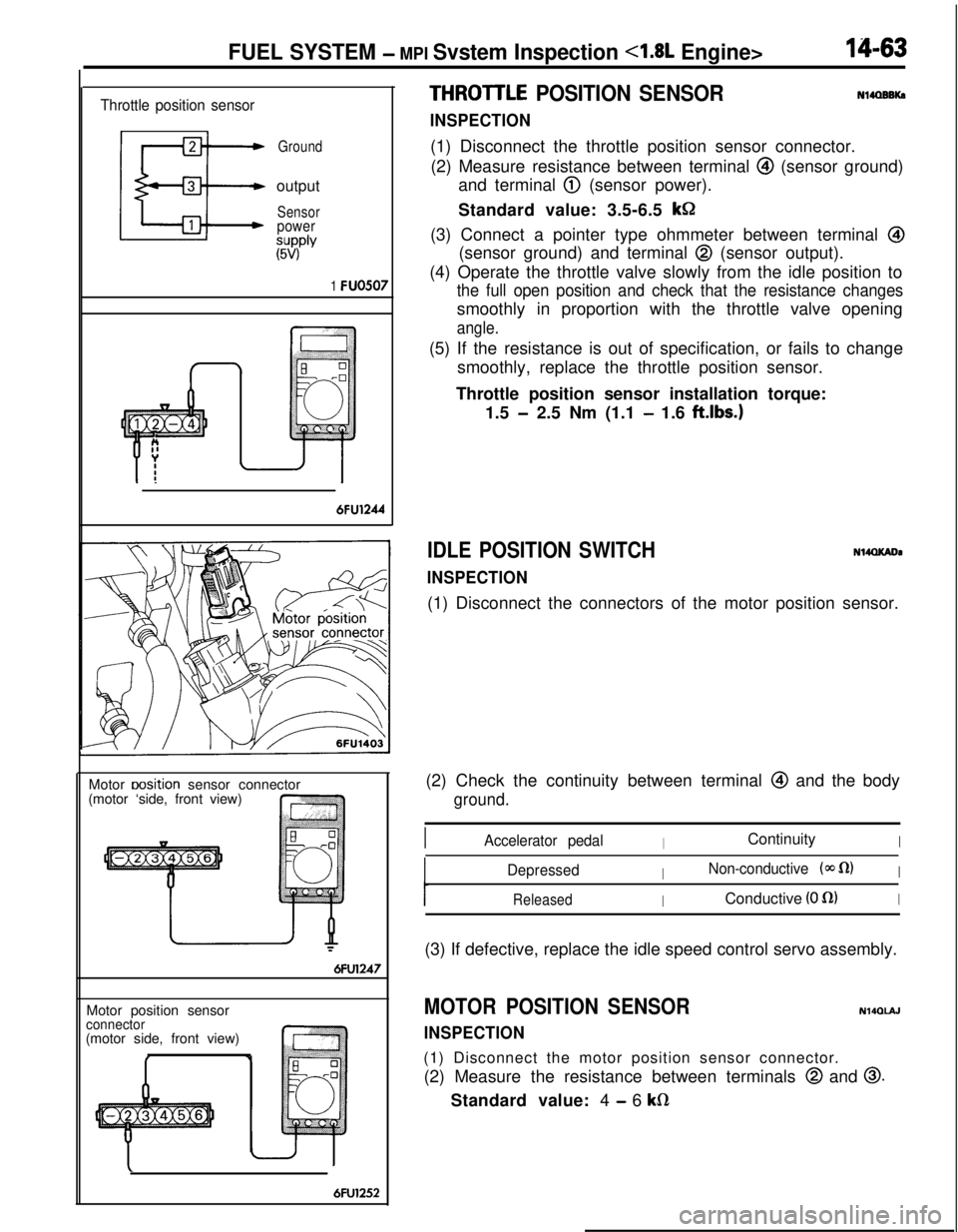
THROITLE POSITION SENSOR
INSPECTION
Nl4OBBKa(1) Disconnect the throttle position sensor connector.
(2) Measure resistance between terminal
@I (sensor ground)
and terminal
@ (sensor power).
Standard value: 3.5-6.5
kGI(3) Connect a pointer type ohmmeter between terminal
@(sensor ground) and terminal
@ (sensor output).
(4) Operate the throttle valve slowly from the idle position to
the full open position and check that the resistance changessmoothly in proportion with the throttle valve opening
angle.(5) If the resistance is out of specification, or fails to change
smoothly, replace the throttle position sensor.
Throttle position sensor installation torque:
1.5
- 2.5 Nm (1.1 - 1.6 ftlbs.)
IDLE POSITION SWITCH
INSPECTION
N14QKADa(1) Disconnect the connectors of the motor position sensor.
(2) Check the continuity between terminal
@ and the body
ground.
IAccelerator pedalIContinuityI
DepressedINon-conductive (@J fl)I
ReleasedIConductive (0 fl)I(3) If defective, replace the idle speed control servo assembly.
MOTOR POSITION SENSOR
INSPECTION
N140lAJ(1) Disconnect the motor position sensor connector.
(2) Measure the resistance between terminals
@ and 0.Standard value: 4
- 6 kfi
Page 518 of 1216
14-64FUEL SYSTEM -MPI System Inspection <1.8L Engine>
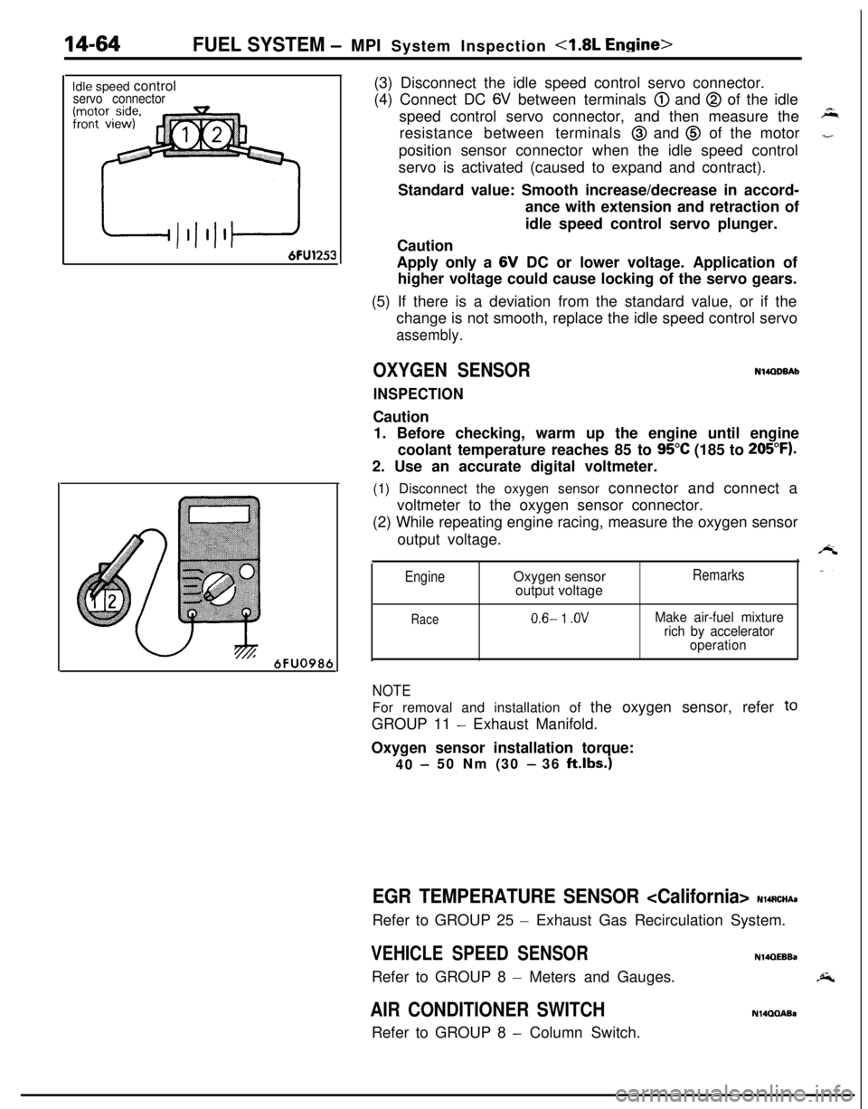
Idle speed controlservo connector
6FU098t(3) Disconnect the idle speed control servo connector.
(4) Connect DC
6V between terminals @) and @ of the idle
speed control servo connector, and then measure the
resistance between terminals
@ and @ of the motor
position sensor connector when the idle speed control
servo is activated (caused to expand and contract).
Standard value: Smooth increase/decrease in accord-
ance with extension and retraction of
idle speed control servo plunger.
Caution
Apply only a 6V DC or lower voltage. Application of
higher voltage could cause locking of the servo gears.
(5) If there is a deviation from the standard value, or if the
change is not smooth, replace the idle speed control servo
assembly.
OXYGEN SENSORN14QDBAb
INSPECTIONCaution
1. Before checking, warm up the engine until engine
coolant temperature reaches 85 to
95°C (185 to 205°F).2. Use an accurate digital voltmeter.
(1) Disconnect the oxygen sensor connector and connect a
voltmeter to the oxygen sensor connector.
(2) While repeating engine racing, measure the oxygen sensor
output voltage.
EngineOxygen sensor
output voltageRemarks
Race0.6- 1 .OVMake air-fuel mixture
rich by accelerator
operation
NOTEFor removal and installation of the oxygen sensor, refer
toGROUP 11
- Exhaust Manifold.
Oxygen sensor installation torque:
40
-50 Nm (30 - 36 klbs.)
EGR TEMPERATURE SENSOR
- Exhaust Gas Recirculation System.
VEHICLE SPEED SENSORN14QEEBaRefer to GROUP 8
- Meters and Gauges.
AIR CONDITIONER SWITCHRefer to GROUP 8
- Column Switch.
N14QQABa
Page 519 of 1216
FUEL SYSTEM - MPI Svstem InsDection <1.8L Engine>14-65
3FUO349
/--
’ 3FU03991
Idle speed controlservo connector(motor side, front view)
3FUO393
INHIBITOR SWITCHN14QRACsRefer to GROUP 21
- Service Adjustment Procedures.
POWER STEERING OIL PRESSURE SWITCH
N14flCJBRefer to GROUP 19 for power steering system inspection.
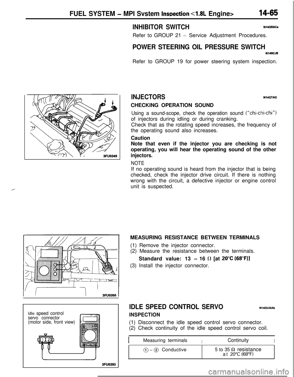
INJECTORSN14QTAGCHECKING OPERATION SOUND
Using a sound-scope, check the operation sound (“chi-chi-chi”)of injectors during idling or during cranking.
Check that as the rotating speed increases, the frequency of
the operating sound also increases.
Caution
Note that even if the injector you are checking is not
operating, you will hear the operating sound of the other
injectors.
NOTEIf no operating sound is heard from the injector that is being
checked, check the injector drive circuit. If there is nothing
wrong with the circuit, a defective injector or engine control
unit is suspected.
MEASURING RESISTANCE BETWEEN TERMINALS
(1) Remove the injector connector.
(2) Measure the resistance between the terminals.
Standard value: 13
- 16 L(Z [at 20°C (68”F)I(3) Install the injector connector.
IDLE SPEED CONTROL SERVO
INSPECTION
NlQQUAAb(1) Disconnect the idle speed control servo connector.
(2) Check continuity of the idle speed control servo coil.
IMeasuring terminalsIContinuityI
@ - @ Conductive5 to 35 fi resistance
at 20°C (68°F)
Page 520 of 1216
14-66FUEL SYSTEM -MPI System Inspection 4.8L Engine>
6FU1253
-1 Batterv
I6FUO751
03AOO50
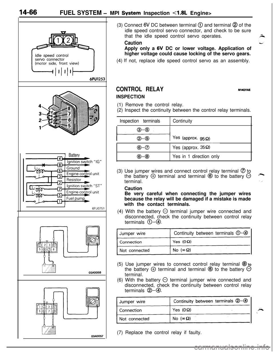
03AOO57(3) Connect
6V DC between terminal @ and terminal @ of the
idle speed control servo connector, and check to be sure
that the idle speed control servo operates.
CautionApply only a 6V DC or lower voltage. Application of
higher voltage could cause locking of the servo gears.
(4)
If not, replace idle speed control servo as an assembly.
CONTROL RELAY
INSPECTION
NWWAE(1) Remove the control relay.
(2) Inspect the continuity between the control relay terminals.
Inspection terminalsContinuity
l---$+-l Yes (approx. 9552)
B-0
@-@
~~~
Yes (approx. 35Q)
Yes in 1 direction only(3) Use jumper wires and connect control relay terminal
@ to
the battery
@ terminal and terminal @ to the battery @
terminal.Caution
Be very careful when connecting the jumper wires
because the relay will be damaged if a mistake is made
with the contact terminals.
(4) With the battery
0 terminal jumper wire connected and
disconnected, check the continuity between control relay
terminals @-@I.
Continuity between terminals 0-B(5) Use jumper wires to connect control relay terminal
@I to
the battery
@ terminal and terminal @ to the battery 0
terminal.(6) With the battery
0 terminal jumper wire connected and
disconnected, check the continuity between control relay
terminals @-@I.
Continuity between terminals 0-a
1(7) Replace the control relay if faulty.
Page 521 of 1216

FUEL SYSTEM - MPI System Inspection <1.8L Engine>
POWER TRANSISTOR
Refer to GROUP 8
- Ignition System
14-67
NlQRCGAAIR CONDITIONER POWER RELAY
Refer to GROUP 24
- Air Conditioner.
N14RCLBPURGE CONTROL SOLENOID VALVE
N14RCKARefer to GROUP 25
- Evaporative Emission Control System.
EGR CONTROL SOLENOID VALVE
N14RCLARefer to GROUP 25
- Exhaust Gas Recirculation System.
Page 522 of 1216
14-68FUEL SYSTEM - MPI System Inspection <2.0L DOHC Engine>
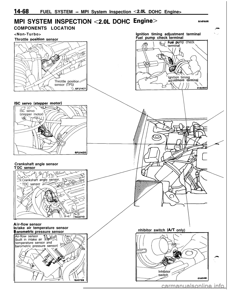
MPI SYSTEM INSPECTION <2.0L DOHCCOMPONENTS LOCATION
Throttle
Dosition sensor
Crankshaft angle sensor
‘DC sensor
N14PAANIgnition timing adjustment terminal
Fuelpumpcheck terminal
I /B \ Q-terminalFuelpump check\Ignition timing adjustment terminal
Fuelpumpcheck terminal
ustment terminalir-flow sensor
takeair temperature sensor
arometric pressure sensornhibitor switch (A/T only)
OlA040i
Page 523 of 1216
![MITSUBISHI ECLIPSE 1991 Service Manual FUEL SYSTEM - MPI System Inspection <2.0L DOHC Engine>
EGR control solenoid valve
[Calif. only]
Purge control solenoid valve
1
/AF--Y:rIgnition coil, Power transistor
Oxygen sensorPower
steering flu MITSUBISHI ECLIPSE 1991 Service Manual FUEL SYSTEM - MPI System Inspection <2.0L DOHC Engine>
EGR control solenoid valve
[Calif. only]
Purge control solenoid valve
1
/AF--Y:rIgnition coil, Power transistor
Oxygen sensorPower
steering flu](/img/19/57104/w960_57104-522.png)
FUEL SYSTEM - MPI System Inspection <2.0L DOHC Engine>
EGR control solenoid valve
[Calif. only]
Purge control solenoid valve
1
/AF--Y:rIgnition coil, Power transistor
Oxygen sensorPower
steering fluid Dressure switch
Coolant temDerature sensor