engine MITSUBISHI ECLIPSE 1991 Service Manual
[x] Cancel search | Manufacturer: MITSUBISHI, Model Year: 1991, Model line: ECLIPSE, Model: MITSUBISHI ECLIPSE 1991Pages: 1216, PDF Size: 67.42 MB
Page 535 of 1216
_-
FUEL SYSTEM - MPI System Inspection <2.0L DOHC Engine>'I4181
OlLO22Z
CONTROL RELAY
INSPECTIONNWWAC
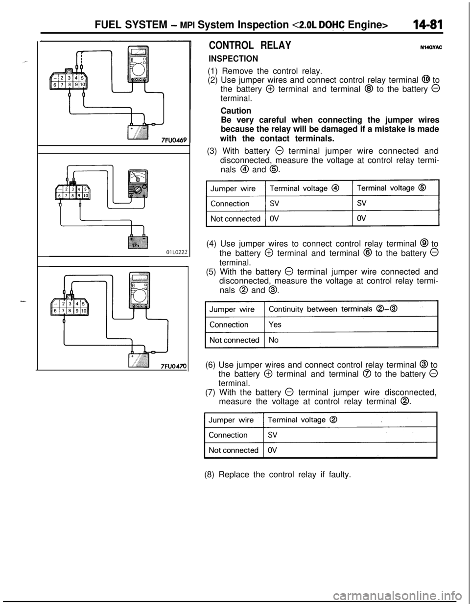
(1) Remove the control relay.
(2) Use jumper wires and connect control relay terminal
@I to
the battery
@ terminal and terminal @ to the battery 0
terminal.Caution
Be very careful when connecting the jumper wires
because the relay will be damaged if a mistake is made
with the contact terminals.
(3) With battery
0 terminal jumper wire connected and
disconnected, measure the voltage at control relay termi-
nals
@I and 0.(4) Use jumper wires to connect control relay terminal
@ to
the battery
@ terminal and terminal @ to the battery 0
terminal.(5) With the battery
@ terminal jumper wire connected and
disconnected, measure the voltage at control relay termi-
nals
@I and 0.
Continuity between terminals 0-0
)(6) Use jumper wires and connect control relay terminal
@ to
the battery
@ terminal and terminal @ to the battery 0
terminal.(7) With the battery
0 terminal jumper wire disconnected,
measure the voltage at control relay terminal
0.
31(8) Replace the control relay if faulty.
Page 536 of 1216
14-82FUEL SYSTEM - MPI System Inspection <2.0L DOHC Engine>
\ \\I \3FUO352
,\ \
\I \3FUO353
,\ ‘\R/
\ \\I \3FUo354
POWER TRANSISTORRefer to GROUP 8
- Ignition System
NlIAcQAl
a-4
AIR CONDITIONER POWER RELAYN14NCl.a -Refer to GROUP 24
- Air Conditioner.
PURGE CONTROL SOLENOID VALVEN14RCKARefer to GROUP 25
- Evaporative Emission Control System.
EGR CONTROL SOLENOID VALVE
N14NCURefer to GROUP 25
- Exhaust Gas Recirculation System.
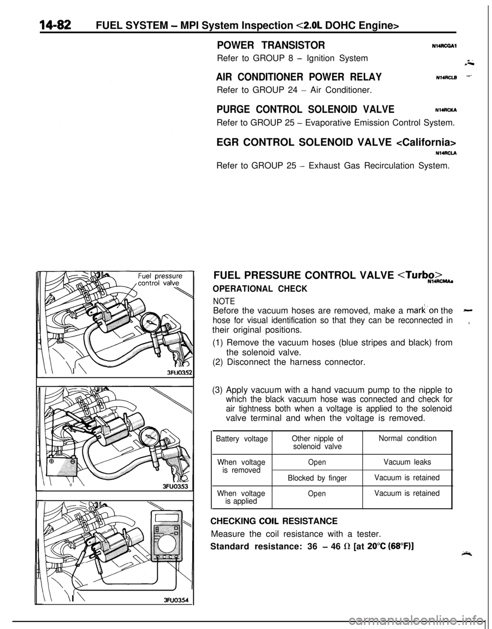
FUEL PRESSURE CONTROL VALVE
NOTEBefore the vacuum hoses are removed, make a mark’on the
-
hose for visual identification so that they can be reconnected in,their original positions.
(1) Remove the vacuum hoses (blue stripes and black) from
the solenoid valve.
(2) Disconnect the harness connector.
(3) Apply vacuum with a hand vacuum pump to the nipple to
which the black vacuum hose was connected and check for
air tightness both when a voltage is applied to the solenoidvalve terminal and when the voltage is removed.
Battery voltageOther nipple of
solenoid valveNormal condition
When voltage
is removed
When voltage
is applied
OpenVacuum leaks
Blocked by fingerVacuum is retained
OpenVacuum is retainedCHECKING
COIL RESISTANCE
Measure the coil resistance with a tester.
Standard resistance: 36
- 46 R [at 20°C (68”F)]
Page 537 of 1216
INJECTORFUEL SYSTEM
- Injector14-83
* ‘- REMOVAL AND INSTALLATIONNWSA-A
Post-installation Operation
l Measurement of Fuel Pressure(Refer to P.14-44. 52.)
4.8L Engine><2.0L DOHC
Engilme>11R7-11 Nm
-hl ft.lbs.-zF!
;533i5,b;m-. .-Y-71s4-6 Nma-3-4 ft.lbs.
03AOlSS::,
4*12:
Center cover
Connection for control harness
Delivery pipe
d-- -13. Insulator4-6 Nm
3-4
ft.lbs.
lo-13 Nm
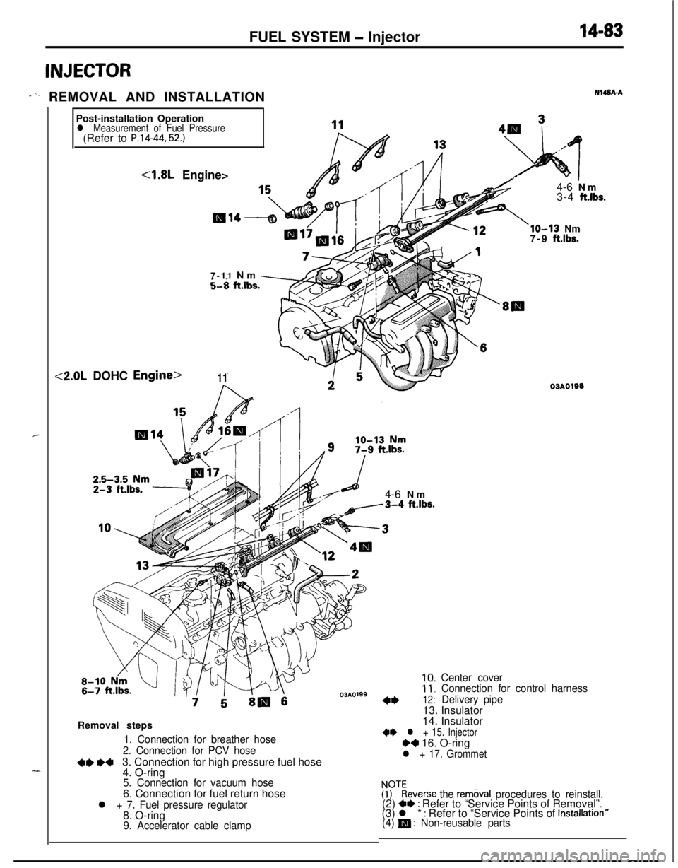
7-9 ft.lbs.Removal steps
1. Connection for breather hose
2. Connection for PCV hose
+e *+3. Connection for high pressure fuel hose
4. O-ring
5. Connection for vacuum hose6. Connection for fuel return hose
l + 7. Fuel pressure regulator8. O-ring
9. Accelerator cable clamp
03AO19014. Insulator
** l + 15. InjectorH 16. O-ringl + 17. Grommet
!PTkeverse the rem&al procedures to reinstall.(2) +* : Refer to “Service Points of Removal”.
(3) l * : Refer to “Service Points of Installatron”(4) m : Non-reusable parts
Page 538 of 1216
14-84FUEL SYSTEM - Injector
03*0095
Delivery pipe03A0095-SERVICE POINTS OF REMOVAL
H4s0m1‘~
3.DISCONNECTION OF THE HIGH PRESSURE FlJFL HOSE /;;
Bleed the residual pressure within the fuel pipe line’& as to~prevent the flow of fuel.
For information concerning the method to be folfowed for
bleeding the residual pressure, refer to
P.14-44.Caution
Cover the hose connection with rags to prevent splash,
of fuel that could be caused by some residual pressure
in the fuel pipe line.
12. REMOVAL OF DELIVERY PIPE/ 15. INJECTOR
Remove the deliver-y pipe (with the injectors attached to it).Caution
Care must be taken, when removing the delivery pipe,
not to drop the injector.
INSPEiZTION
INJECTORS
N14NGAA
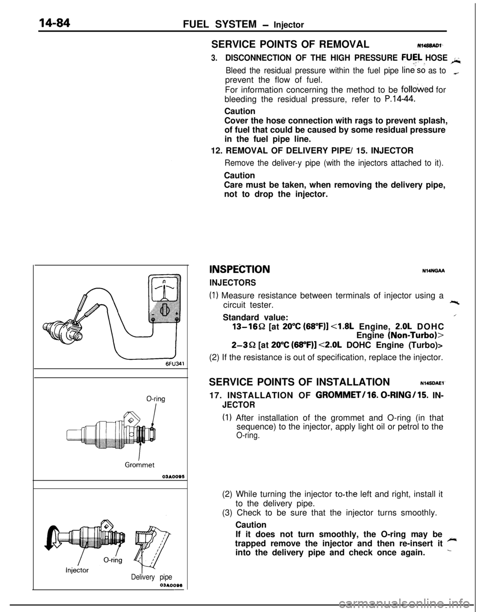
(1) Measure resistance between terminals of injector using a
circuit tester.+-%Standard value:
/13-1652 [at
20°C (68”F)] <1.8L Engine, 2.0L DOHC
Engine
(NoniTurbo)>
2-3Q [at 20°C (68”F)] <2.0L DOHC Engine (Turbo)>
(2) If the resistance is out of specification, replace the injector.
SERVICE POINTS OF INSTALLATION
N14SDAEl’17. INSTALLATION OF
GROMMET/lG. 0-RINGI15. IN-
JECTOR
(I) After installation of the grommet and O-ring (in that
sequence) to the injector, apply light oil or petrol to the
O-ring.(2) While turning the injector to.the left and right, install it
to the delivery pipe.
(3) Check to be sure that the injector turns smoothly.
Caution
If it does not turn smoothly, the O-ring may be
~trapped remove the injector and then re-insert it
into the delivery pipe and check once again.
L
Page 539 of 1216
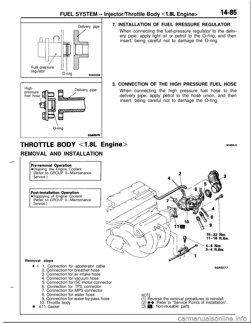
FUEL SYSTEM - Injector/Throttle Body <1.8L Engine>14-85
Delivery pipe
Fuel pres
regulator
O-ringY pipe
O-kg
OWOO797. INSTALLATION OF FUEL PRESSURE REGULATOR
When connecting the fuel-pressure regulator to the deliv-
ery pipe, apply light oil or petrol to the O-ring, and then
insert, being careful not to damage the O-ring.
3. CONNECTION OF THE HIGH PRESSURE FUEL HOSE
When connecting the high pressure fuel hose to the
delivery pipe, apply petrol to the hose union, and then
insert, being careful not to damage the O-ring.
THROTTLE BODY 4.8L Engine>REMOVAL AND INSTALLATION
Removal steps
l 41. Connection for accelerator cable2. Connection for breather hose
3. Connection for air intake hose
4. Connection for vacuum hose
5. Connection for
ISC motor connector
6. Connection for TPS connector7. Connection for MPS connector
8. Connection for water hose
9. Connection for water by-pass hose
10. Throttle bodyl 4 11. Gasket
03AO277
NOTE(1) Reverse the removal procedures to reinstall.(2) I)+ : Refer to “Service Points of Installation”.(3) m : Non-reusable parts
Page 541 of 1216
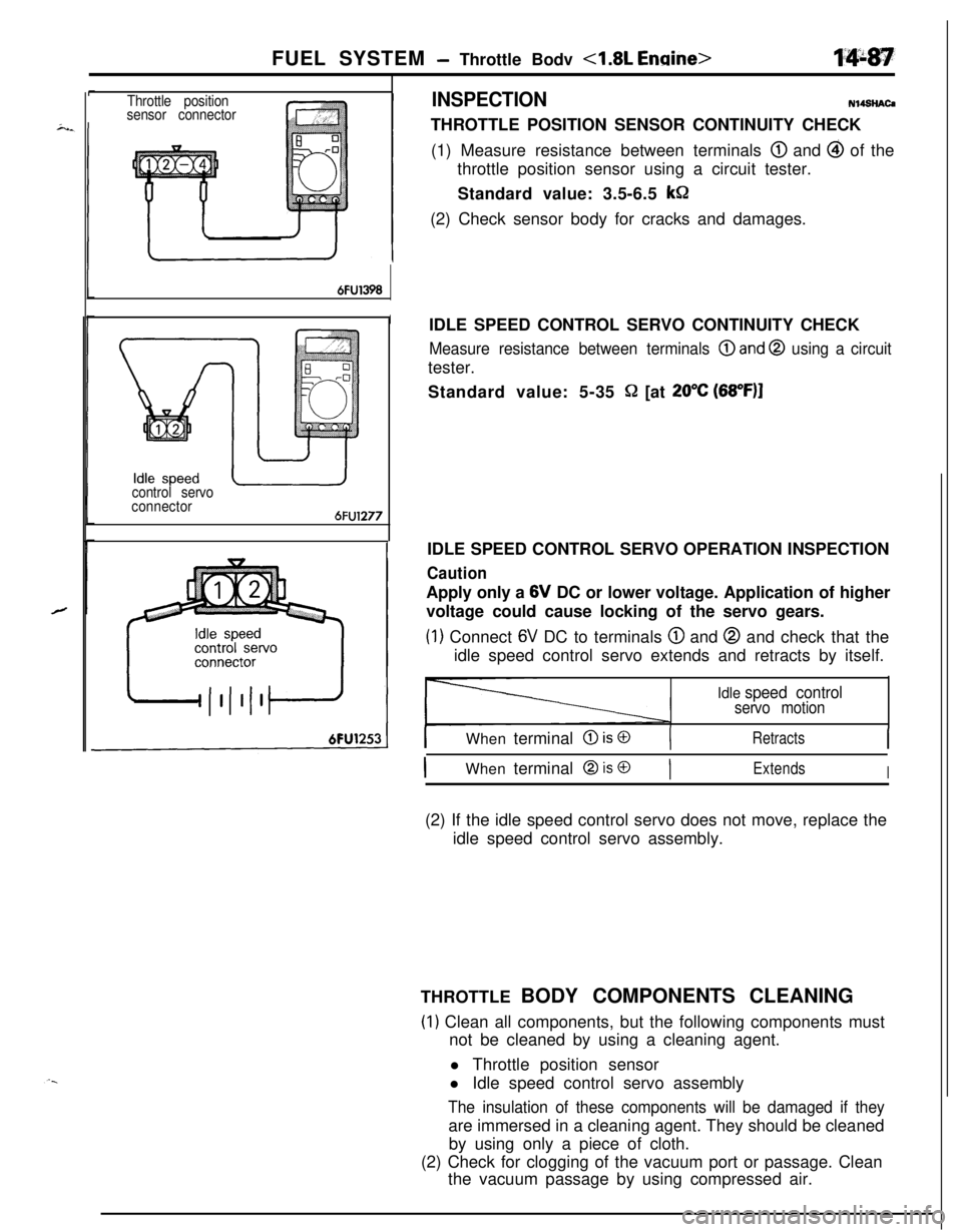
FUEL SYSTEM - Throttle Bodv <1.8L Engine>
Throttle position
sensor connectorINSPECTIONN14SHAC4
THROTTLE POSITION SENSOR CONTINUITY CHECK
(1) Measure resistance between terminals
@ and @ of the
throttle position sensor using a circuit tester.
Standard value: 3.5-6.5
kSZ(2) Check sensor body for cracks and damages.
6FU1398
I
control servo
connector
6FU1277
IIDLE SPEED CONTROL SERVO OPERATION INSPECTIONIDLE SPEED CONTROL SERVO CONTINUITY CHECK
Measure resistance between terminals @and @ using a circuittester.
Standard value: 5-35
Q [at 20°C (68”F)I
CautionApply only a 6V DC or lower voltage. Application of higher
voltage could cause locking of the servo gears.
(1) Connect 6V DC to terminals @ and @ and check that the
idle speed control servo extends and retracts by itself.
Idle speed controlservo motion
I
IWhen terminal @ is @(RetractsI
IWhen terminal @ is @)ExtendsI(2) If the idle speed control servo does not move, replace the
idle speed control servo assembly.
THROTTLE BODY COMPONENTS CLEANING
(1) Clean all components, but the following components must
not be cleaned by using a cleaning agent.
l Throttle position sensor
l Idle speed control servo assembly
The insulation of these components will be damaged if theyare immersed in a cleaning agent. They should be cleaned
by using only a piece of cloth.
(2) Check for clogging of the vacuum port or passage. Clean
the vacuum passage by using compressed air.
Page 542 of 1216
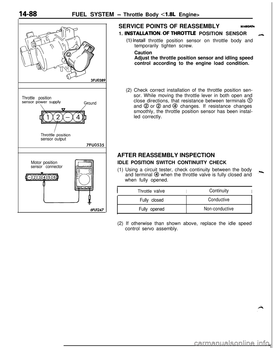
14-88FUEL SYSTEM - Throttle Body 4.8L Engine>
,
Throttle position
round
sensor output
7FUO535
Motor positionsensor connector
6FU1247SERVICE POINTS OF REASSEMBLYN14SGADa
1. INSTALLATlON.OF THROlTLE POSITION SENSOR
H
(1) Install throttle position sensor on throttle body and
temporarily tighten screw.
Caution
Adjust the throttle position sensor and idling speed
control according to the engine load condition.
(2) Check correct installation of the throttle position sen-
sor. While moving the throttle lever in both open and
close directions, that resistance between terminals
@and
@ or @ and @ changes. If resistance changes
smoothly, the throttle position sensor has been instal-
led correctly.
AFTER REASSEMBLY INSPECTION
IDLE POSITION SWITCH CONTINUITY CHECK
(1) Using a circuit tester, check continuity between the body
and terminal
@I when the throttle valve is fully closed and,riwhen fully opened.
Throttle valveIContinuityI
Fully closed
Fully openedConductive
Non-conductive(2) If otherwise than shown above, replace the idle speed
control servo assembly.
Page 543 of 1216
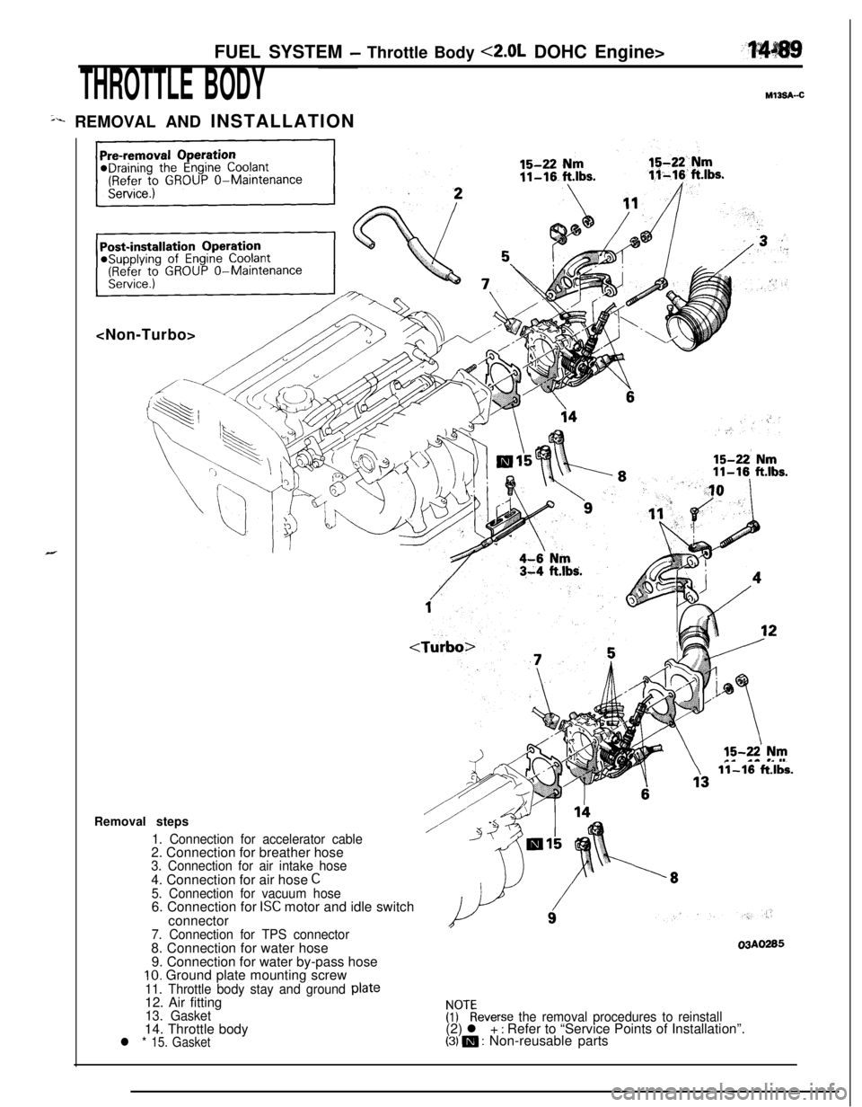
FUEL SYSTEM - Throttle Body <2.0L DOHC Engine>
THROTTLE BODYMl3s&c
sr REMOVAL AND INSTALLATION
11-16 ft.lbs.
Removal steps
1. Connection for accelerator cable2. Connection for breather hose
3. Connection for air intake hose4. Connection for air hose
C5. Connection for vacuum hose6. Connection for ISC motor and idle switch
connector
7. Connection for TPS connector8. Connection for water hose
9. Connection for water by-pass hose
10. Ground plate mounting screw
11. Throttle body stay and ground plate12. Air fitting
13. Gasket14. Throttle body
l * 15. Gasket03A0285
!Fbeverse the removal procedures to reinstall(2) l + : Refer to “Service Points of Installation”.(3) m : Non-reusable parts
Page 544 of 1216
14-90FUEL SYSTEM - Throttle Body <2.0L DOHC Engine>
r
Air intake
plenum side
03AO259JDISASSEMBLY AND REASSEMBLYSERVICE POINTS OF INSTALLAtlON
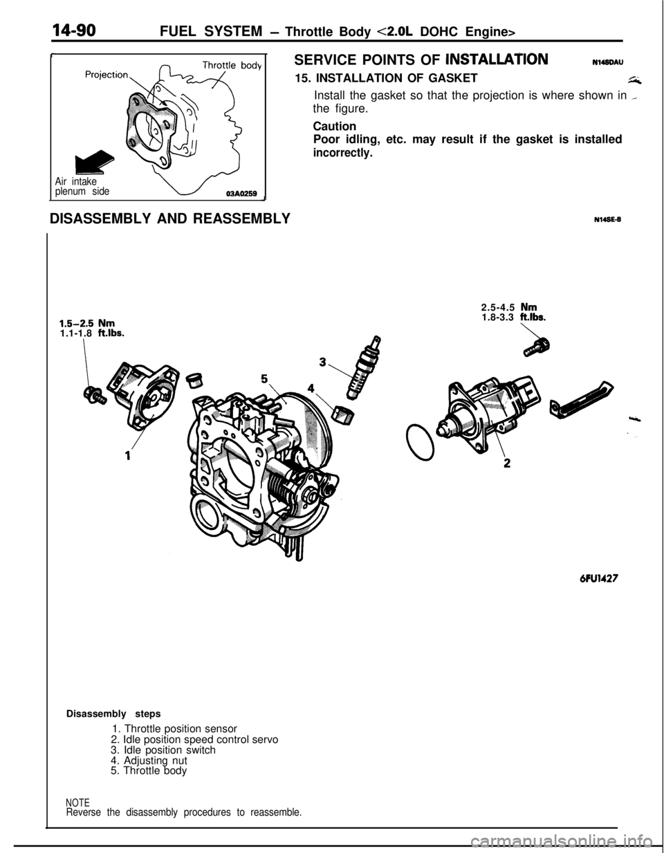
Nl49DAU15. INSTALLATION OF GASKET
GInstall the gasket so that the projection is where shown in
._the figure.
Caution
Poor idling, etc. may result if the gasket is installed
incorrectly.
1.5-2.5 Nm
1.1-1.8 ftlbs.
Nl49C92.5-4.5
Nm1.8-3.3 ft.lbs.MU1427
Disassembly steps
1. Throttle position sensor
2. Idle position speed control servo
3. Idle position switch
4. Adjusting nut
5. Throttle body
NOTEReverse the disassembly procedures to reassemble.
Page 546 of 1216
14-92FUEL SYSTEM- Throttle Bodv <2.0L DOHC Engine>
Iw--
7FUOOl I
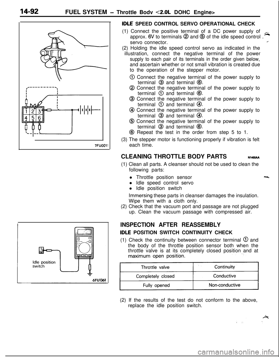
tDLE SPEED CONTROL SERVO OPERATIONAL CHECK
(1) Connect the positive terminal of a DC power supply of
approx.
6V to terminals @ and @ of the idle speed control .
~servo connector.
/(2) Holding the idle speed control servo as indicated in the
illustration, connect the negative terminal of the power
supply to each pair of its terminals in the order given below,and ascertain whether or not small vibration is created due
to the operation of the stepper motor.
0 Connect the negative terminal of the power supply to
terminal
@ and terminal @.
@ Connect the negative terminal of the power supply to
terminal
@ and terminal @I.
@ Connect the negative terminal of the power supply to
terminal
@ and terminal @I.
@I Connect the negative terminal of the power supply to
terminal
@ and terminal @I.
@ Connect the negative terminal of the power supply to
terminal
@ and terminal @.
@ Repeat the test in the order from step 5 to 1.
(3) The stepper motor is functioning properly if vibration is felt
each time.
CLEANING THROTTLE BODY PARTSN14SlAA
(1) Clean all parts. A cleanser should not be used to clean the
following parts:
l Throttle position sensor
l Idle speed control servo
l Idle position switch
Immersing these parts in cleanser damages the insulation.
Wipe them with a cloth only.
(2) Check that the vacuum port and passage are not plugged
up. Clean the vacuum passage with compressed air.
INSPECTION AFTER REASSEMBLY
tDLE POSITION SWITCH CONTINUITY CHECK
(1) Check the continuity between connector terminal
@ and
the body of the throttle position sensor both when the
throttle valve is at its completely closed position and at
maximum open position.
11(2) If the results of the test do not conform to the above,
replace the idle position switch.