engine MITSUBISHI ECLIPSE 1991 Owner's Guide
[x] Cancel search | Manufacturer: MITSUBISHI, Model Year: 1991, Model line: ECLIPSE, Model: MITSUBISHI ECLIPSE 1991Pages: 1216, PDF Size: 67.42 MB
Page 53 of 1216
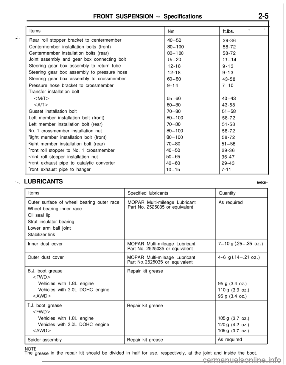
FRONT SUSPENSION - Specifications2-5Items
Rear roll stopper bracket to centermember
Centermember installation bolts (front)
Centermember installation bolts (rear)
Joint assembly and gear box connecting bolt
Steering gear box assembly to return tube
Steering gear box assembly to pressure hose
Steering gear box assembly to crossmember
Pressure hose bracket to crossmember
Transfer installation bolt
Nmftlbs. I’, ‘,
40-5029-36
80-10058-72
80-I 0058-72
15-20II-1412-18
9-13
12-189-13
60-8043-58
9-14
7-10
55-6040-43
Gusset installation bolt
70-8051-58Left member installation bolt (front)
80-10058-72
Left member installation bolt (rear)
70-8051-58
Vo. 1 crossmember installation nut80-10058-72qight member installation bolt (front)
80-10058-72?ight member installation bolt (rear)
70-8051-58
+ont roll stopper to No. 1 crossmember40-5029-36
?ont roll stopper installation nut50-6536-47
Iront exhaust pipe to catalytic converter40-6029-43
‘rant exhaust pipe to hangerIO-157-11
‘-. LUBRICANTSNO2CD--
ItemsSpecified lubricantsQuantity
Outer surface of wheel bearing outer race
MOPAR Multi-mileage LubricantAs required
Wheel bearing inner racePart No. 2525035 or equivalent
Oil seal lip
Strut insulator bearing
Lower arm ball joint
Stabilizer link
Inner dust coverMOPAR Multi-mileage Lubricant
Part No. 2525035 or equivalent
7-10 g (.25-.35 oz.)
Outer dust cover
MOPAR Multi-mileage Lubricant
Part
No.2525035 or equivalent4-6
g (.14-.21 oz.)
B.J. boot grease
Repair kit grease
1.8L engine
95 g (3.4 oz.)
Vehicles with
2.0L DOHC engine110 g (3.9 oz.)
T.J. boot grease
Repair kit grease
1.8L engine105 g (3.7 oz.)
Vehicles with
2.0L DOHC engine120 g (4.2 oz.)
Spider assemblyRepair kit greaseAs required
NOTEThe grease in the repair kit should be divided in half for use, respectively, at the joint and inside the boot.
Page 68 of 1216
FRONT SUSPENSION - Drive Shaft
IllA0127
llE560
Grease
llE563
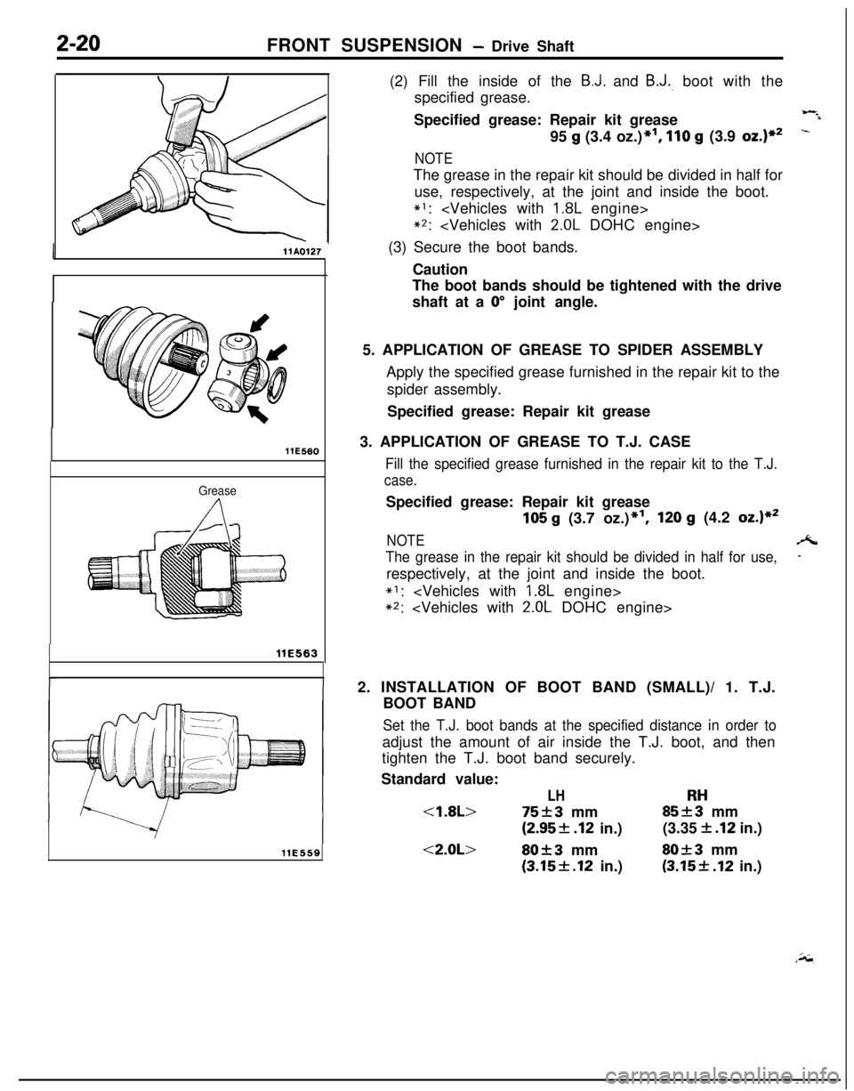
llE559(2) Fill the inside of the
B.J. and B.J., boot with the
specified grease.
Specified grease: Repair kit grease
Wil95
g (3.4 oz.)*I, 110 g (3.9 oz.)**-
NOTEThe grease in the repair kit should be divided in half for
use, respectively, at the joint and inside the boot.
*I:
*2:
(3) Secure the boot bands.
Caution
The boot bands should be tightened with the drive
shaft at a
0” joint angle.
5. APPLICATION OF GREASE TO SPIDER ASSEMBLY
Apply the specified grease furnished in the repair kit to the
spider assembly.
Specified grease: Repair kit grease
3. APPLICATION OF GREASE TO T.J. CASE
Fill the specified grease furnished in the repair kit to the T.J.
case.Specified grease: Repair kit grease
105 g (3.7 oz.)*‘I,120 g (4.2 oz.)**
NOTEA
The grease in the repair kit should be divided in half for use,-respectively, at the joint and inside the boot.
*I:
*2:
2. INSTALLATION OF BOOT BAND (SMALL)/ 1. T.J.
BOOT BAND
Set the T.J. boot bands at the specified distance in order toadjust the amount of air inside the T.J. boot, and then
tighten the T.J. boot band securely.
Standard value:
LHRH
(2.95f .I2 in.)(3.35 f .I2 in.)
<2.0L>80f3 mmSO+3 mm
(3.15f.12 in.)(3.15+ .I2 in.)
Page 92 of 1216
2-44FRONT SUSPENSION -Centermember and Crossmember
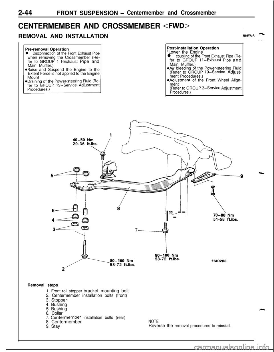
CENTERMEMBER AND CROSSMEMBER
REMOVAL AND INSTALLATION
Pre-removal Operation
l Disconnection of the Front Exhaust Pipewhen removing the Crossmember (Re-
fer to GROUP 1 l-Exhaust Pipe and
Main Muffler.)
@Raise and Suspend the Engine to the
Extent Force is not applied to the EnginePost-installation Operation
*Lower the Enginel coupling of the Front Exhaust Pipe (Re-fer to GROUP ll-Exhaust Pipe and
Main Muffler.)
@Air bleeding of the Power-steering Fluid
(Refer to GROUP 19-Service Adjust-
ment Procedures.)*Adjustment of the Front Wheel Align-
ment
(Refer to GROUP
2-Service AdjustmentProcedures.)
40-50 Nm
29-36 ft.lbs.
! *J
I”---
7
9
80-100 Nm
58-72 ft.lbs.
\80-100 Nm
58-72 ft.lbs.
70-86 Nm
51-58 ft.lbs.llA0283
Removal steps
1. Front roll stopper bracket mounting bolt
2. Centermember installation bolts (front)3. Stopper
4. Bushing
5. Bushing
6. Collar7. Centermember installation bolts (rear)
8. Centermember
9. StayNOTEReverse the removal procedures to reinstall.
4
Page 109 of 1216
REAR AXLE - Troubleshooting3-7
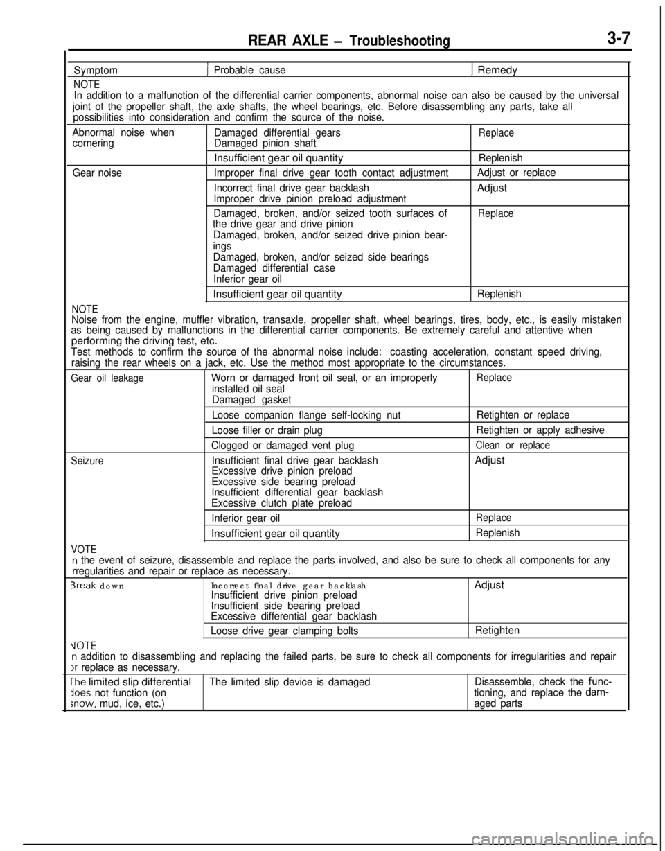
Symptom
NOTE
1 Probable cause1 Remedy
In addition to a malfunction of the differential carrier components, abnormal noise can also be caused by the universal
joint of the propeller shaft, the axle shafts, the wheel bearings, etc. Before disassembling any parts, take all
possibilities into consideration and confirm the source of the noise.
Abnormal noise when
Damaged differential gears
ReplacecorneringDamaged pinion shaftInsufficient gear oil quantity
Replenish
Gear noiseImproper final drive gear tooth contact adjustmentAdjust or replace
Incorrect final drive gear backlashAdjust
Improper drive pinion preload adjustment
Damaged, broken, and/or seized tooth surfaces of
Replacethe drive gear and drive pinion
Damaged, broken, and/or seized drive pinion bear-
ings
NOTE
Damaged, broken, and/or seized side bearings
Damaged differential case
Inferior gear oilInsufficient gear oil quantity
Replenish
Noise from the engine, muffler vibration, transaxle, propeller shaft, wheel bearings, tires, body, etc., is easily mistaken
as being caused by malfunctions in the differential carrier components. Be extremely careful and attentive whenperforming the driving test, etc.
Test methods to confirm the source of the abnormal noise include:coasting acceleration, constant speed driving,
raising the rear wheels on a jack, etc. Use the method most appropriate to the circumstances.
Gear oil leakageWorn or damaged front oil seal, or an improperlyReplace
installed oil seal
Damaged gasket
Seizure
VOTE
Loose companion flange self-locking nut
Loose filler or drain plug
Clogged or damaged vent plug
Insufficient final drive gear backlash
Excessive drive pinion preload
Excessive side bearing preload
Insufficient differential gear backlash
Excessive clutch plate preload
Inferior gear oilInsufficient gear oil quantityRetighten or replace
Retighten or apply adhesive
Clean or replaceAdjust
Replace
Replenish
n the event of seizure, disassemble and replace the parts involved, and also be sure to check all components for any
rregularities and repair or replace as necessary.
3reak downIncorrect final drive gear backlashAdjustInsufficient drive pinion preload
Insufficient side bearing preload
Excessive differential gear backlash
Loose drive gear clamping boltsRetighten
VOTEn addition to disassembling and replacing the failed parts, be sure to check all components for irregularities and repairIr
replace as necessary.
The limited slip differentialThe limited slip device is damagedDisassemble, check the func-
lees not function (ontioning, and replace the dam-
;now, mud, ice, etc.)aged parts
Page 149 of 1216
BRAKES - Anti-lock Braking System Troubleshooting5-9
ANTI-LOCK BRAKING SYSTEM
-- TROUBLESHOOTINGNO!JEBAE
PARTICULAR CHARACTERISTICS OF
THE ANTI-LOCK BRAKING SYSTEMModels equipped with the anti-lock braking system
(A.B.S.) may exhibit one or more of the following
characteristics from time to time, but none of these
is abnormal.
(1) A pulsing feeling in the brake pedal, or vibration
of the body or the steering wheel, when the
anti-lock braking system is activated by sudden
braking or by braking on a slippery road surface.Actually, this phenomenon is an indication that
the anti-lock braking system is functioning nor-
mally.(2) When the vehicle speed reaches approximately
6 km/h (4 mph) after the engine is started and
the vehicle starts off (for the first time), a
whining motor noise may be heard from the
engine compartment if the vehicle is traveling in
a quiet place, but this noise is simply the result
of a self-check being made of the anti-lock
braking system operation.
TROUBLESHOOTING METHODSProblems related to the anti-lock braking system
(A.B.S.) can be classified into two general categor-
ies: problems in the electrical system and those in
the hydraulic system.For problems in the electrical system, the
self-diagnosis function is built into the electronic control
unit (E.C.U.) causing the A.B.S. warning light to
illuminate as a warning to the driver.
Problems in the hydraulic system (poor braking,
etc.) can be located in the same way as for ordinary
brakes. There is, however, the necessity to check todetermine whether the problem is related to ordin-
ary brake components or to the components relatedto the A.B.S.
HOW TO USE THE TROUBLESHOOTING
FLOW CHART(1) Using the flow chart, check the ABS warning
light light-up sequence and check the condition
of braking operation.
(2) Following the check chart listed in the remedy
column, perform the checks. There are [Explana-tion] and [Hint] in each check chart. Refer to
them when troubleshooting.
NOTEECU: Electronic control unit
HU: Hydraulic unit
MUT: Multi-use tester
Page 150 of 1216
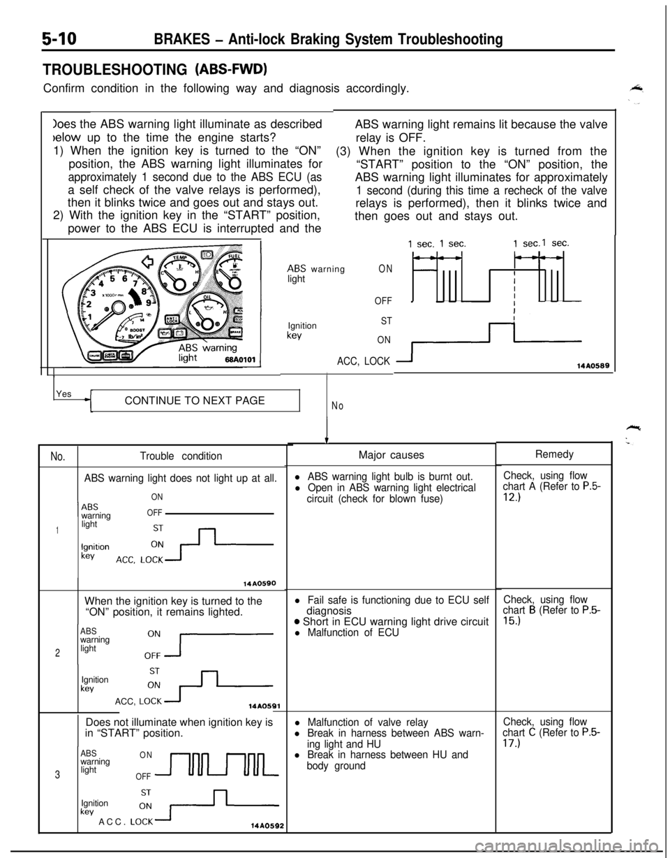
Ioes the ABS warning light illuminate as describedbelow up to the time the engine starts?
1) When the ignition key is turned to the “ON”
position, the ABS warning light illuminates for
approximately 1 second due to the ABS ECU (asa self check of the valve relays is performed),
then it blinks twice and goes out and stays out.
2) With the ignition key in the “START” position,
power to the ABS ECU is interrupted and the
5-10BRAKES - Anti-lock Braking System Troubleshooting
TROUBLESHOOTING (ABS-FWD)Confirm condition in the following way and diagnosis accordingly.
ABS warning light remains lit because the valve
relay is OFF.
(3) When the ignition key is turned from the
“START” position to the “ON” position, the
ABS warning light illuminates for approximately
1 second (during this time a recheck of the valverelays is performed), then it blinks twice and
then goes out and stays out.
ABS warning
lightON
OFF
1Ignition
kev
ST
ON
ACC, LOCK
IYes
CONTINUE TO NEXT PAGE
No
No.Trouble condition
ABS warning light does not light up at all.
ON
1 --ABSwarningOFF
1lightlgnitlon
kev
14A0590When the ignition key is turned to the
“ON” position, it remains lighted.
ABSwarning
2light
Ignition
kevACC,
LO:+14AOSQlDoes not illuminate when ignition key is
in “START” position.
ABSONwarning
3lightOFFUULkev ACC.
LO:-+-Ignition14A0592
1 sec. 1 sec.1 sec.1 sec.
---
IIII
3114AO589
IMajor causes
l ABS warning light bulb is burnt out.Check, using flow
l Open in ABS warning light electricalchart A (Refer to P.5-
circuit (check for blown fuse)12.)
l Fail safe is functioning due to ECU selfdiagnosis
o Short in ECU warning light drive circuitl Malfunction of ECU
l Malfunction of valve relayl Break in harness between ABS warn-
ing light and HU
l Break in harness between HU and
body groundRemedy
Check, using flow
chart
B (Refer to P.5-
15.)
Check, using flow
chart C (Refer to P.5-17.)
Page 153 of 1216
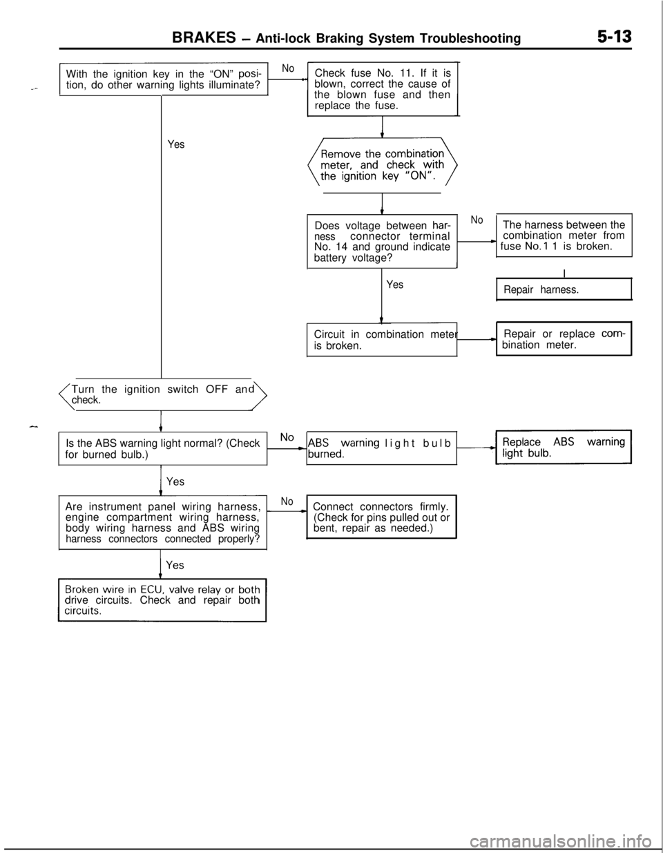
BRAKES - Anti-lock Braking System Troubleshooting5-13With the ignition key in the “ON”
posi-Nol
tion, do other warning lights illuminate?
II
YesCheck fuse No. 11. If it is
blown, correct the cause of
the blown fuse and then
replace the fuse.
Does voltage between
har-NoThe harness between thenessconnector terminalcombination meter from
No. 14 and ground indicate) fuse No.1 1 is broken.
battery voltage?
II
Yes
Repair harness.Circuit in combination meter
is broken.Repair or replace
com-
* bination meter.
Turn the ignition switch OFF an
(check.
IIs the ABS warning light normal? (Check
for burned bulb.)
No L A&zed%rning light bulb -Are instrument panel wiring harness,
_Noengine compartment wiring harness,~ Connect connectors firmly.
(Check for pins pulled out or
bent, repair as needed.) body wiring harness and ABS wiring
harness connectors connected properly?drive circuits. Check and repair both
Page 155 of 1216
![MITSUBISHI ECLIPSE 1991 Owners Guide BRAKES - Anti-lock Braking System Troubleshooting5-15
--
BABS warning light illuminated after the engine is started and remains on.
[Explanation]
This is the symptom when the ABS ECU does not
power up MITSUBISHI ECLIPSE 1991 Owners Guide BRAKES - Anti-lock Braking System Troubleshooting5-15
--
BABS warning light illuminated after the engine is started and remains on.
[Explanation]
This is the symptom when the ABS ECU does not
power up](/img/19/57104/w960_57104-154.png)
BRAKES - Anti-lock Braking System Troubleshooting5-15
--
BABS warning light illuminated after the engine is started and remains on.
[Explanation]
This is the symptom when the ABS ECU does not
power up due to broken ECU power circuit, etc.,
when the fail safe function operates and isolates thesystem or when the warning light drive circuit is
short circuited.
MAINIGNITION
FUSIBLELINK
@IEYCH
z
A:7
J/B
rb
0
10A
I
:c
r
I
1vAI23
f
! 127ABS ECUCheck, using check chart
E-l -E-6.Check warning light drive
circuit.
t
Does the ABS warning lightNoShort in ECU transistor
remainilluminated even
with the ECU connector dis-
connected?
I
1 YesIReplace
I
Does the ABS warning light
remainilluminated even
with the ECU connector dis-
connected?
Yes
IReplace HU or replacevalve relay.I
Page 164 of 1216
![MITSUBISHI ECLIPSE 1991 Owners Guide 5-24BRAKES - Anti-lock Braking System Troubleshooting
E-6 Abnormality of motor drive circuit
[Explanation]The ABS ECU illuminates the warning light for the
motor relay and motor in the following cases MITSUBISHI ECLIPSE 1991 Owners Guide 5-24BRAKES - Anti-lock Braking System Troubleshooting
E-6 Abnormality of motor drive circuit
[Explanation]The ABS ECU illuminates the warning light for the
motor relay and motor in the following cases](/img/19/57104/w960_57104-163.png)
5-24BRAKES - Anti-lock Braking System Troubleshooting
E-6 Abnormality of motor drive circuit
[Explanation]The ABS ECU illuminates the warning light for the
motor relay and motor in the following cases.
l When the motor relay does not function
lWhen there is trouble with the motor itself and it
does not revolve
lWhen the motor ground line is disconnected and
[Hint]If there is motor operation noise when wheel speed
exceeds
Gkm/h (4mph) when starting up after the
engine is started, there is a broken or short circuitedmotor monitor wire.
the motor does not revolve
l When the motor continues to revolve
14A0605Does the motor make a
YesBroken wire or short cir-noise when wheel speedcuit in motor monitor line
exceeds 6 km/h (4 mph)?
1Repair the harness be-
tween HU and ECU.
, NoRemove the motor relay.
Remove the motor relay andcheck resistance values.
No. 85-No. 86:resistancevalue
30-60 52No.30-No.87: no continui-
ty
Battery voltage is applied onterminals No. 86 and No.85
grounded.No.30-No.87: continuity
IYesIs pump motor ground con-
NoConnect ground wire.
netted normally?
IlYes
motor relay and re-
move HU connector.>Does voltage between body
connector terminal 51 and
No c Broken wire in pump
motor power circuit
ground indicate battery vol-
tage?4Repair the harness.
YesIs resistance between body
NoMalfunction of harnessconnector terminal No. 2 andbetween HU and ECUNo.26 30-60 ohms?iII1Repair harness.
Page 165 of 1216
BRAKES - Anti-lock Braking System Troubleshooting5-25
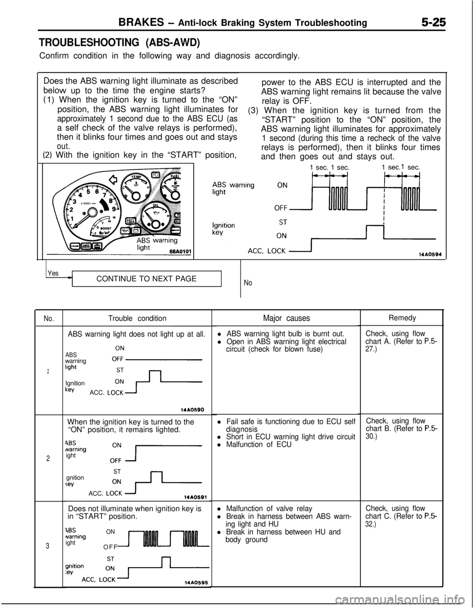
TROUBLESHOOTING (ABS-AWD)Confirm condition in the following way and diagnosis accordingly.
C
F
>oes the ABS warning light illuminate as described
relow up to the time the engine starts?
1) When the ignition key is turned to the “ON”
position, the ABS warning light illuminates for
approximately 1 second due to the ABS ECU (asa self check of the valve relays is performed),
then it blinks four times and goes out and stays
out.power to the ABS ECU is interrupted and the
ABS warning light remains lit because the valve
relay is OFF.
t:2) With the ignition key in the “START” position,(3) When the ignition key is turned from the
“START” position to the “ON” position, the
ABS warning light illuminates for approximately
1 second (during this time a recheck of the valverelays is performed), then it blinks four times
and then goes out and stays out.IO1
-1 sec. 1 sec.1
sec.1 sec.
14AO594
YesCONTINUE TO NEXT PAGE
No
No.
1
2
3
Trouble condition
ABS warning light does not light up at all.
ABSwarninglightOFFIgnitionkey
ACC.
LO;-+
14AOSSOWhen the ignition key is turned to the
“ON” position, it remains lighted.
4BSNamingight
0:7gnition
wACC.
LO:+14A0591Does not illuminate when ignition key is
in “START” position.
4BSNamingightONOFF
14A0595
Major causes
l ABS warning light bulb is burnt out.
l Open in ABS warning light electrical
circuit (check for blown fuse)
l Fail safe is functioning due to ECU self
diagnosis
l Short in ECU warning light drive circuitl Malfunction of ECU
l Malfunction of valve relay
l Break in harness between ABS warn-
ing light and HU
l Break in harness between HU and
body groundRemedy
Check, using flow
chart A. (Refer to
P.5-27.)
Check, using flow
chart B. (Refer to P.5-30.)
Check, using flow
chart C. (Refer to
P.5-
32.)