engine MITSUBISHI ECLIPSE 1991 Workshop Manual
[x] Cancel search | Manufacturer: MITSUBISHI, Model Year: 1991, Model line: ECLIPSE, Model: MITSUBISHI ECLIPSE 1991Pages: 1216, PDF Size: 67.42 MB
Page 201 of 1216

BRAKES - Brake Booster5-61Vacuum hose
MAO394
14uoo50
14Y626Vacuum hose
mm (in.)
14A0395
SERVICE POINTS OF REMOVALNow9Al
6. REMOVAL OF VACUUM HOSE WITH CHECK VALVE
NOTE
Since the check valve is fit to the vacuum hose, replace thecheck valve as an assembly unit together with the vacuum
hose if the check valve is defective.
SERVICE POINTS OF INSTALLATIONNOWDAV
10. APPLICATION OF GREASE TO CLEVIS PIN/g. WASHERAfter applying the specified grease to the
clevis pin and
washer, insert the clevis pin and bend the cotter pin tightly.
Grease: MOPAR Multi-mileage Lubricant
Part No. 2525035 or equivalent
7. APPLICATION OF SEALANT TO
FITTINGWhen installing the vacuum hose fitting, apply semi-drying
sealant to its threaded portion.
6. INSTALLATION OF VACUUM HOSE WITH CHECK
VALVE(1) Attach the vacuum hose so that it may be inserted to a
dimension illustrated.
Caution
Prevent interference between the check valve and
brake booster.(2) The vacuum hose at the engine should be securely
connected until it contacts the hexagonal edge of the
fitting, and then should be secured by the hose clip.
Page 206 of 1216
5,966BRAKES - Front Disc Brake
14A04001410399
SERVICE POINTS OF INSTALLATIONNO5LDAG
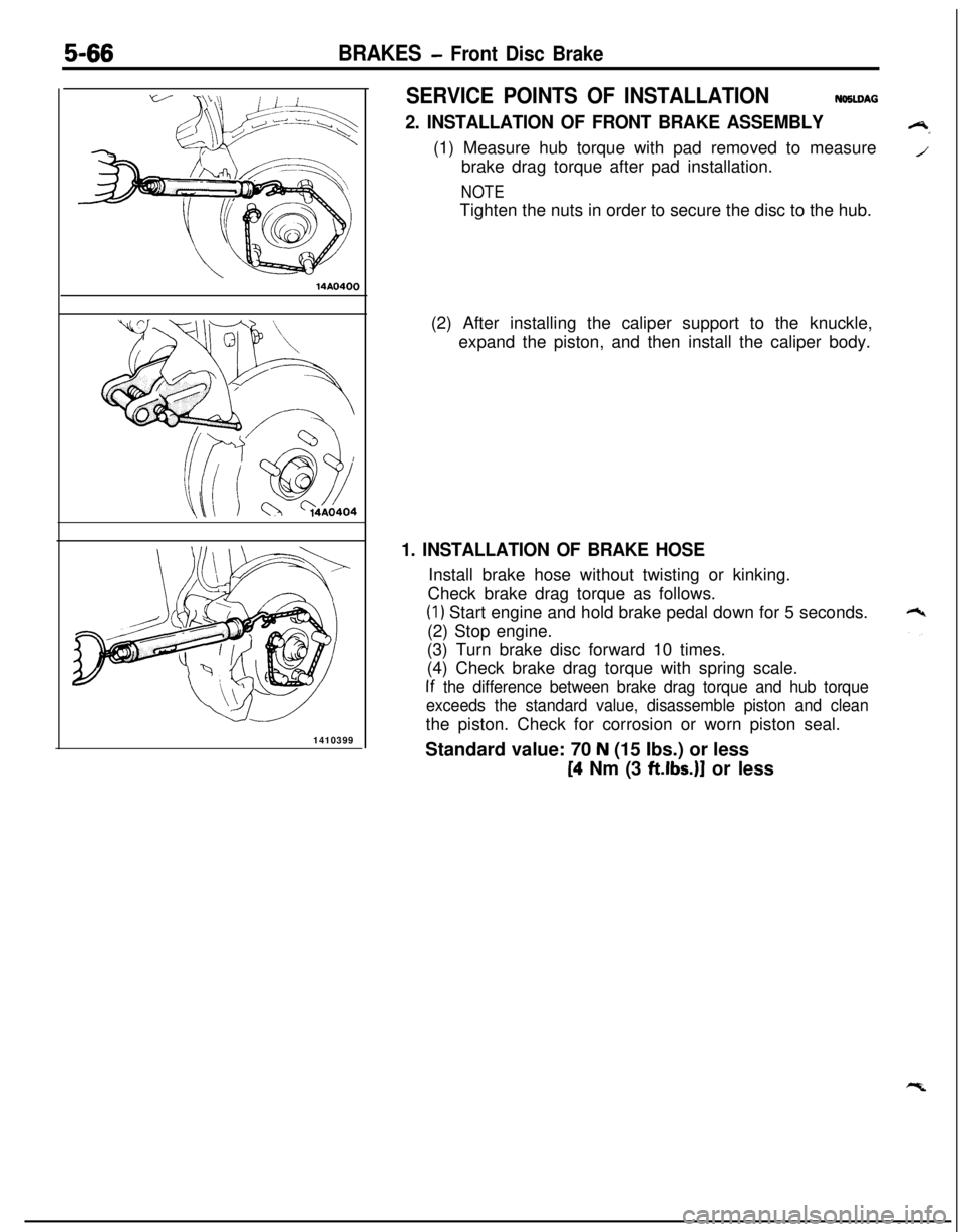
2. INSTALLATION OF FRONT BRAKE ASSEMBLY(1) Measure hub torque with pad removed to measure
brake drag torque after pad installation.
NOTETighten the nuts in order to secure the disc to the hub.
(2) After installing the caliper support to the knuckle,
expand the piston, and then install the caliper body.
1. INSTALLATION OF BRAKE HOSEInstall brake hose without twisting or kinking.
Check brake drag torque as follows.
(1) Start engine and hold brake pedal down for 5 seconds.
(2) Stop engine.
(3) Turn brake disc forward 10 times.
(4) Check brake drag torque with spring scale.
If the difference between brake drag torque and hub torque
exceeds the standard value, disassemble piston and cleanthe piston. Check for corrosion or worn piston seal.
Standard value: 70
N (15 Ibs.) or less[4 Nm (3
ft.lbs.)J or less
Page 216 of 1216
5-76BRAKES - Rear Disc Brake
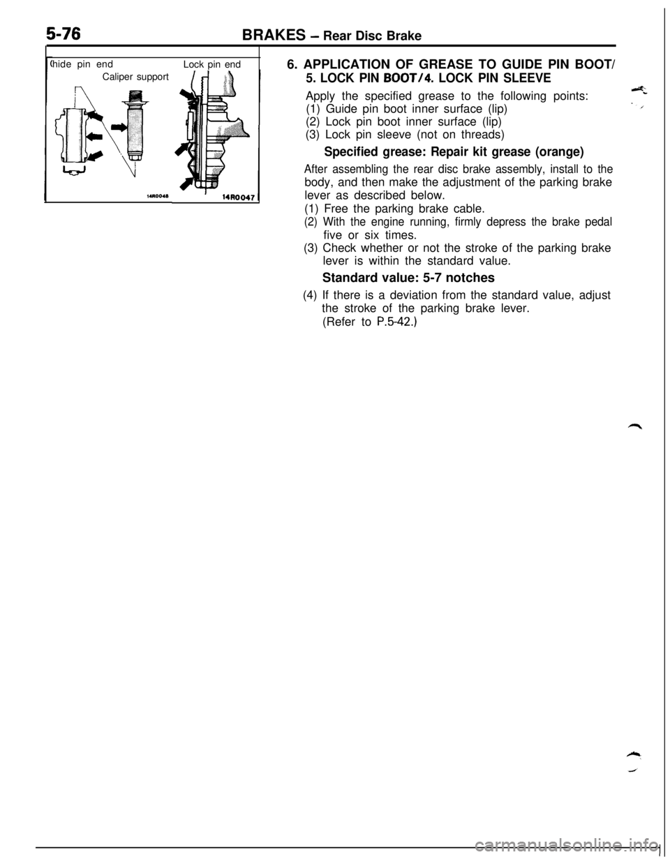
hide pin end
Caliper supportLock pin end
6. APPLICATION OF GREASE TO GUIDE PIN BOOT/
5. LOCK PIN BOOT/4. LOCK PIN SLEEVEApply the specified grease to the following points:
(1) Guide pin boot inner surface (lip)
(2) Lock pin boot inner surface (lip)
(3) Lock pin sleeve (not on threads)
Specified grease: Repair kit grease (orange)
After assembling the rear disc brake assembly, install to thebody, and then make the adjustment of the parking brake
lever as described below.
(1) Free the parking brake cable.
(2) With the engine running, firmly depress the brake pedalfive or six times.
(3) Check whether or not the stroke of the parking brake
lever is within the standard value.
Standard value: 5-7 notches
(4) If there is a deviation from the standard value, adjust
the stroke of the parking brake lever.
(Refer to
P.5-42.)
Page 231 of 1216
6-I
CLUTCH
CONTENTS
CLUTCH CONTROL. . . . . . . . . . . . . . . . . . . . . . . . . . . . . . . . . . . . . . . . .9SPECIFICATIONS. . . . . . . . . . . . . . . . . . ..m........................2
GeneralSpecifications..................................2CLUTCH COVER AND DISC..........................16Lubricants......................................................3
CLUTCH MASTER CYLINDER........................11Service Specifications...................................2Torque Specifications
...................................3
CLUTCH PEDAL..............................................7
TROUBLESHOOTING. . . . . . . . . . . . . . . . . . . . . . . ..*............4
CLUTCHRELEASE CYLINDER . . . . . . . ..a.............13Clutch chatters
SERVICE ADJUSTMENT PROCEDURES . . . . . . .5Clutch noise
Bleeding. . . . . . . . . . . . . . . . . . . . . . . . . . . . . . . . . . . . . . . . . . . . . . . . . . . . . . . .6Clutch pedal feels “heavy”
Clutch Pedal Inspection and Adjustment . . . .
5Clutch slips
SPECIAL TOOL,.,#mmm,.*......B......................*........3Gear shift malfunctionCAUTIONWhen
servicing clutch assemblies or com-
ponents for vehicles with 1.8L engine, doNOT
create dust by sanding or by cleaning
clutch parts with a dry brush or with
compressed air. (A water dampened cloth
should be used). The clutch disc contains
“Asbestos Fibers” which can become air-
borne if dust is created during serviceoperations. Breathing dust containing
“Asbestos Fibers”may cause seriousbodily
harm.
Page 232 of 1216
6-2CLUTCH - SDecifications
SPECIFICATIONS
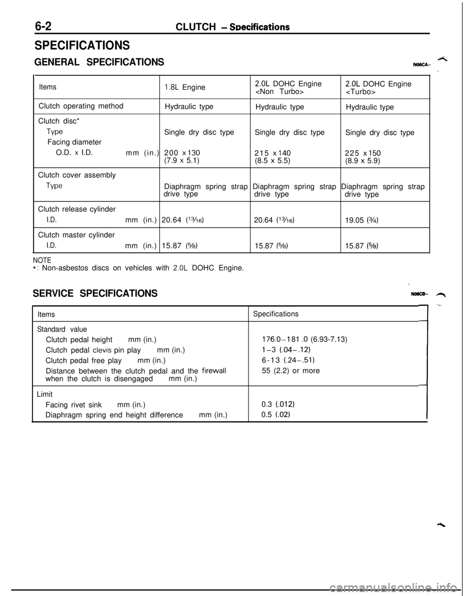
GENERAL SPECIFICATIONS
Items1.8L Engine2.0L DOHC Engine
Clutch operating method
Hydraulic type
Hydraulic type
Hydraulic type
Clutch disc*
TypeSingle dry disc type
Single dry disc type
Single dry disc type
Facing diameter
O.D.
x I.D.
mm (in.) 200 x 130215 x 140225 x 150(7.9 x 5.1)
(8.5 x 5.5)
(8.9 x 5.9)
Clutch cover assembly
TypeDiaphragm spring strap Diaphragm spring strap Diaphragm spring strap
drive type
drive type
drive type
Clutch release cylinder
I.D.mm (in.) 20.64 (13/16)20.64 (13/6)19.05 (3h)Clutch master cylinder
I.D.mm (in.) 15.87 (%)15.87 (%)15.87 (543)
NOTE*: Non-asbestos discs on vehicles with 2.0L DOHC Engine.
SERVICE SPECIFICATIONS
Items
Standard valueClutch pedal heightmm (in.)
Clutch pedal
clevis pin playmm (in.)
Clutch pedal free playmm (in.)
Distance between the clutch pedal and the firewall
when the clutch is disengagedmm (in.)
Limit
Facing rivet sinkmm (in.)
Diaphragm spring end height differencemm (in.)
NO6lX- .H,
Specifications
176.0-I 81 .O (6.93-7.13)
l-3 (.04-.12)6-13 (.24-.51)
55 (2.2) or more
0.3 (012)
0.5
(.02)L-
Page 249 of 1216
7-l
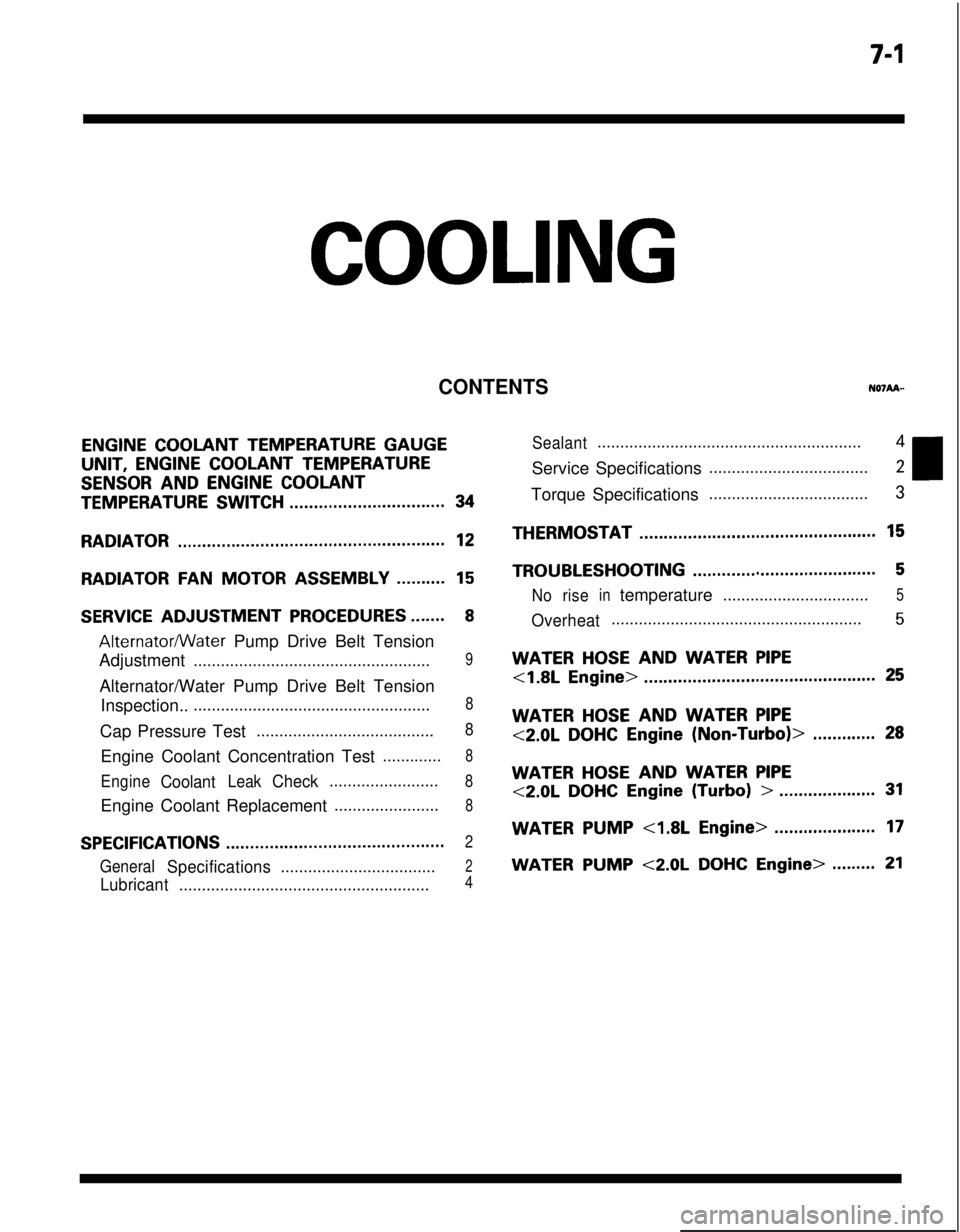
COOLING
CONTENTS
ENGINE COOLANT TEMPERATURE GAUGEUNIT,
ENGINE COOLANT TEMPERATURE
SENSOR AND ENGINE COOLANT
TEMPERATURE SWITCH................................34
RADIATOR.......................................................12
RADIATORFANMOTOR ASSEMBLY..........15
SERVICE ADJUSTMENT PROCEDURES.......8
Alternatormater Pump Drive Belt Tension
Adjustment
....................................................9Alternator/Water Pump Drive Belt Tension
Inspection..
....................................................8Cap Pressure Test
.......................................8Engine Coolant Concentration Test
.............8
EngineCoolantLeakCheck........................8Engine Coolant Replacement
.......................8
SPECIFICATIONS.............................................2
GeneralSpecifications..................................2
Lubricant.......................................................4
Sealant..........................................................4Service Specifications
...................................2Torque Specifications
...................................3THERMOSTAT
.................................................15
TROUBLESHOOTING......................................5
Noriseintemperature................................5
Overheat.......................................................5
WATER HOSE AND WATER PIPE
<1.8L Engine>................................................25
WATER HOSE AND WATER PIPE
<2.0LDOHCEngine(Non-Turbo)>.............28
WATER HOSE AND WATER PIPE
<2.0LDOHCEngine(Turbo)>....................31
WATERPUMP<1.8LEngine>.....................17
WATER PUMP <2.0L DOHC Engine>.........21
Page 250 of 1216
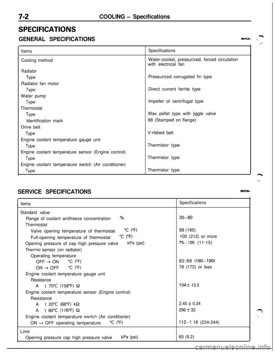
7-2COOLING - Specifications
SPECIFICATIONS
GENERAL SPECIFICATIONSIcNQ7cA- I
ItemsCooling method
Radiator
TypeRadiator fan motor
TypeWater pump
Type
Thermostat
TypeIdentification mark
Drive belt
TypeEngine coolant temperature gauge unit
WeEngine coolant temperature sensor (Engine control)
TypeEngine coolant temperature switch (Air conditioner)
WeSpecifications
Water-cooled, pressurized, forced circulation
with electrical fan
Pressurized corrugated fin type
Direct current ferrite type
Impeller of centrifugal type
Wax pellet type with jiggle valve
88 (Stamped on flange)
V-ribbed belt
Thermistor type
Thermistor type
Thermistor type
SERVICE SPECIFICATIONSN07CB.-
Items
Standard valueRange of coolant antifreeze concentration
%
ThermostatValve opening temperature of thermostat
“C (“F)Full-opening temperature of thermostat
“C (“F)Opening pressure of cap high pressure valve
kPa (psi)
Therm0 sensor (on radiator)
Operating temperature
OFF
+ ON“C (“F)ON
--P OFF“C (“F)Engine coolant temperature gauge unit
ResistanceAt
70°C (158°F) QEngine coolant temperature sensor (Engine control)
ResistanceAt
20°C (68°F) kQAt
80°C (176°F) QEngine coolant temperature
switch (Air conditioner)
ON -+ OFF operating temperature
“C (“F)Limit
Opening pressure cap high pressure valve
kPa (psi)
Specifications
30-6088 (190)
100 (212) or more
75-105 (11-15)
82-88 (180-190)
78 (172) or less
104f 13.5
2.45
I!I 0.24
296
+ 32
112-l 18 (234-244)
65 (9.2)
Page 251 of 1216
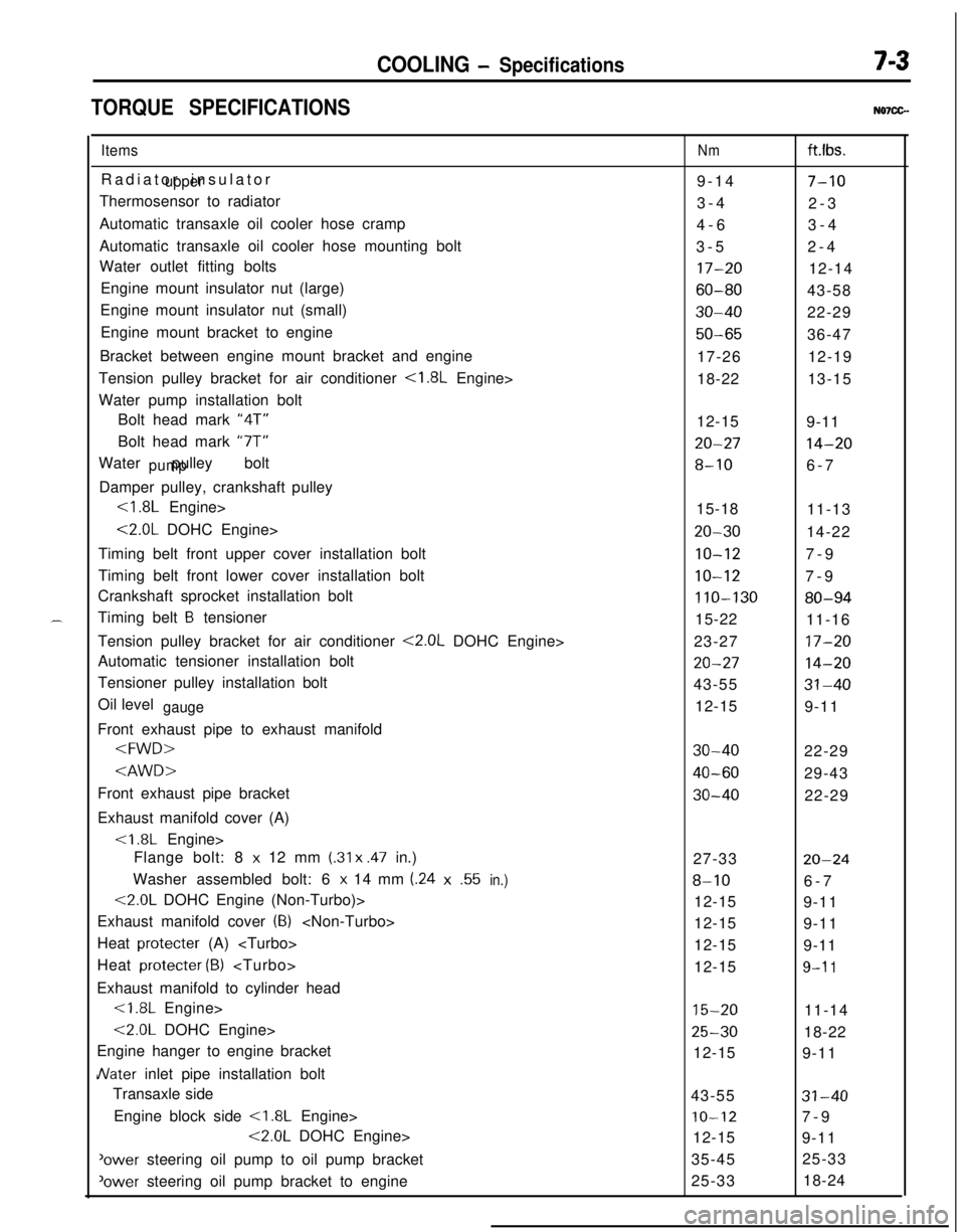
COOLING - Specifications7-3
TORQUE SPECIFICATIONSN07CG.
ItemsRadiator insulator
upperThermosensor to radiator
Automatic transaxle oil cooler hose cramp
Automatic transaxle oil cooler hose mounting bolt
Water outlet fitting bolts
Engine mount insulator nut (large)
Engine mount insulator nut (small)
Engine mount bracket to engine
Bracket between engine mount bracket and engine
Tension pulley bracket for air conditioner
<1.8L Engine>
Water pump installation bolt
Bolt head mark “4T”
Bolt head mark “7T”
Water pulley bolt
pumpDamper pulley, crankshaft pulley
<1.8L Engine>
<2.0L DOHC Engine>
Timing belt front upper cover installation bolt
Timing belt front lower cover installation bolt
Crankshaft sprocket installation bolt
Timing belt
B tensioner
Tension pulley bracket for air conditioner
<2.0L DOHC Engine>
Automatic tensioner installation bolt
Tensioner pulley installation bolt
Oil level
gaugeFront exhaust pipe to exhaust manifold
Exhaust manifold cover (A)
Flange bolt: 8
x 12 mm (.31 x .47 in.)
Washer assembled bolt: 6
x 14 mm (.24x.55in.)
<2.0L DOHC Engine (Non-Turbo)>
Exhaust manifold cover
(8)
Heat protecter (A)
Heat protecter
(B)
Exhaust manifold to cylinder head<1.8L Engine>
<2.0L DOHC Engine>
Engine hanger to engine bracket
JVater inlet pipe installation bolt
Transaxle side
Engine block side
<1.8L Engine>
<2.0L DOHC Engine>
'ower steering oil pump to oil pump bracket
‘ower steering oil pump bracket to engine
Nmft.lbs.
9-14
7-103-4
2-3
4-63-4
3-52-4
17-2012-14
60-8043-58
30-4022-29
50-6536-47
17-2612-19
18-2213-15
12-15
9-11
20-2714-20
8-106-7
15-18
11-13
20-3014-22
IO-127-9
10-127-9
110-13080-9415-22
11-16
23-27
17-20
20-2714-2043-55
31-4012-15
9-11
30-4022-29
40-6029-43
30-4022-29
27-33
20-24
8-106-7
12-15
9-11
12-15
9-11
12-15
9-11
12-15
9-l 1
15-2011-14
25-3018-22
12-15
9-11
43-55
31-40
IO-127-9
12-15
9-11
35-4525-33
25-3318-24
Page 252 of 1216
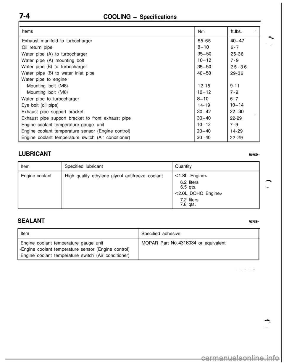
7-4COOLING - Specifications
ItemsExhaust manifold to turbocharger
Oil return pipe
Water pipe (A) to turbocharger
Water pipe (A) mounting bolt
Water pipe
(B) to turbocharger
Water pipe
(B) to water inlet pipe
Water pipe to engine
Mounting bolt
(M8)Mounting bolt
(M6)Water pipe to turbocharger
Eye bolt (oil pipe)
Exhaust pipe support bracket
Exhaust pipe support bracket to front exhaust pipe
Engine coolant temperature gaugeunit
Engine coolant temperature sensor (Engine control)
Engine coolant temperature switch (Air conditioner)
Nmft.lbs. _155-65
40-47
8-106-7
35-5025-36
10-127-9
35-5025-36
40-5029-36
12-159-11
10-127-9
8-106-7
14-19
10-14
30-4222-30
30-4022-29 .’
10-127-9
20-4014-29
30-4022-29
LUBRICANT
ItemEngine coolantSpecified lubricant
High quality ethylene
glycol antifreeze coolantQuantity
6.2 liters
6.5
qts.
<2.0L DOHC Engine>
7.2 liters
7.6 qts.
SEALANTNO7CE-.
ItemEngine coolant temperature gauge unit
-Engine coolant temperature sensor (Engine control)
Engine coolant temperature switch (Air conditioner)Specified adhesive
MOPAR Part No.4318034 or equivalent
Page 253 of 1216
COOLING - Troubleshootina7-5
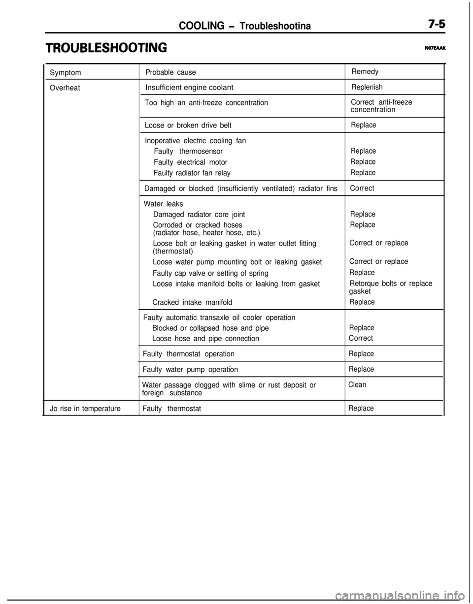
TRO,UBLESHOOTlNG
Symptom
OverheatProbable causeInsufficient engine coolant
Too high an anti-freeze concentrationRemedy
Replenish
Correct anti-freeze
concentration
Loose or broken drive belt
Replace
Inoperative electric cooling fan
Faulty thermosensor
Replace
Faulty electrical motorReplace
Faulty radiator fan relayReplace
Damaged or blocked (insufficiently ventilated) radiator finsCorrect
Water leaks
Damaged radiator core joint
Replace
Corroded or cracked hosesReplace
(radiator hose, heater hose, etc.)
Loose bolt or leaking gasket in water outlet fitting
(thermostat)
Loose water pump mounting bolt or leaking gasket
Faulty cap valve or setting of spring
Loose intake manifold bolts or leaking from gasket
Cracked intake manifold
Faulty automatic transaxle oil cooler operation
Blocked or collapsed hose and pipe
Loose hose and pipe connection
Faulty thermostat operation
Faulty water pump operation
Water passage clogged with slime or rust deposit or
foreign substanceCorrect or replace
Correct or replace
Replace
Retorque bolts or replace
gasket
Replace
Replace
Correct
Replace
Replace
Clean
Jo rise in temperatureFaulty thermostatReplace