ignition MITSUBISHI ECLIPSE 1991 Owner's Guide
[x] Cancel search | Manufacturer: MITSUBISHI, Model Year: 1991, Model line: ECLIPSE, Model: MITSUBISHI ECLIPSE 1991Pages: 1216, PDF Size: 67.42 MB
Page 395 of 1216

ENGINE <2.0L DOHC Engine> - Camshaft and Rocker Arm9-111_ Front of engine (Timing belt side)
0 Co@
6EN0192
MD998306Oil seal
-
Y-II6ENI01946EN030’
1(2) Tighten the bearing caps in the order shown two to
three times by torquing progressively.
Tighten to specification in the final sequence.
(3) Check to be sure that the rocker arm is correctly placedon the lash adjuster and valve stem end.
5. INSTALLATION OF CAMSHAFT OIL SEAL
(1) Install the special tool, Guide, on the camshaft.
(2) Apply oil to the oil seal and insert the seal along the
Guide until it contacts the cylinder head.
(3) Using the special tool, Installer, press-fit the oil seal intothe cylinder head.
2. INSTALLATION OF CAMSHAFT SPROCKET
Using a wrench hold the camshaft at its hexagon (betweenthe
No.2 and No.3 journals) and tighten the bolt to
specification.Caution
Locking the camshaft sprocket with a tool damages the
sprocket.1. INSTALLATION OF CRANK ANGLE SENSOR
(1) Locate the dowel pin on the sprocket side of the intake
camshaft at top.
(2) Align the punch mark on the crank angle sensor housingwith the notch in plate.
NOTE
The crank angle sensor can be installed even when thepunch mark is positioned opposite the notch; however,
the position results in incorrect fuel injection and
ignition timings.
(3) Install the crank angle sensor on the cylinder head.
Page 425 of 1216
--
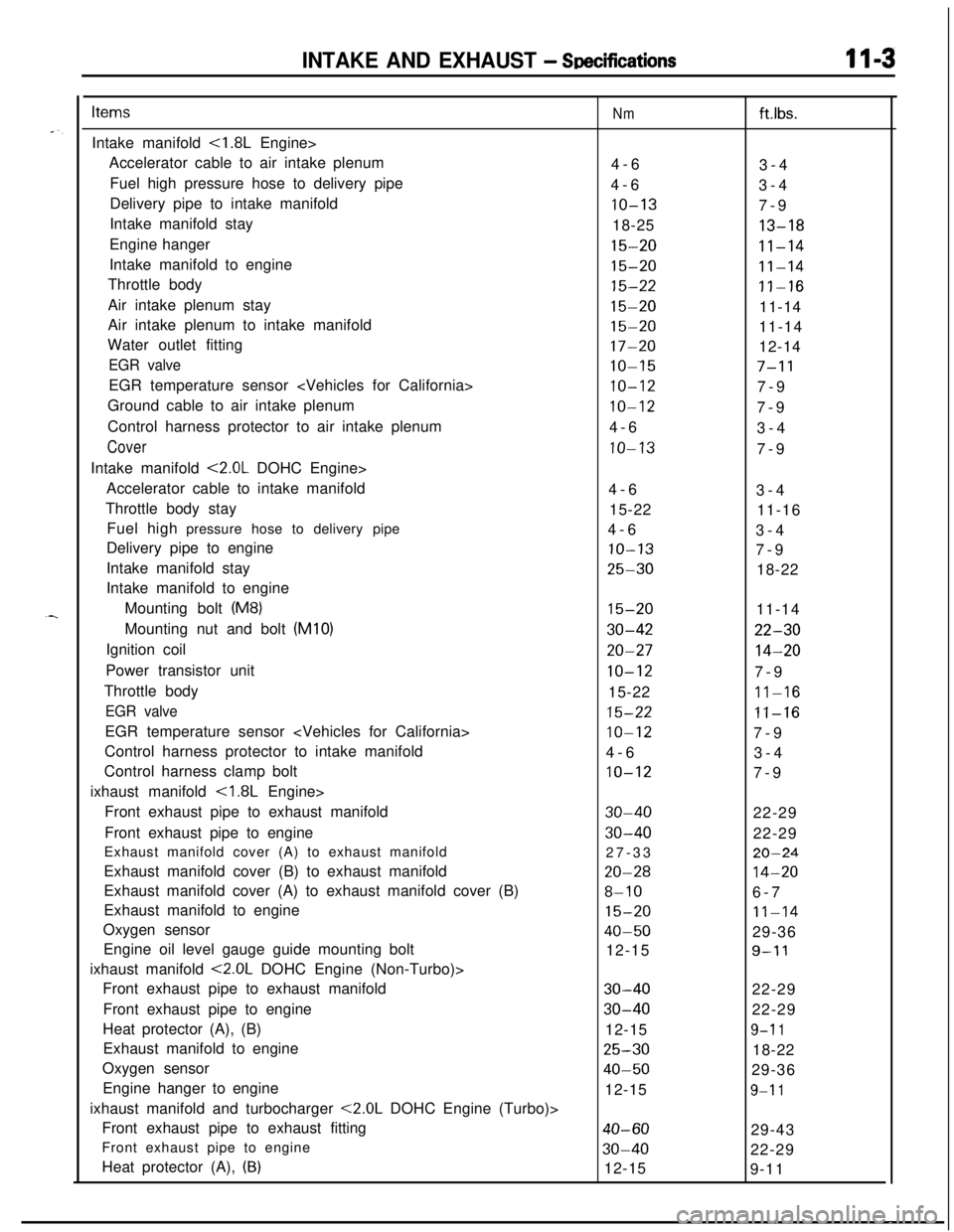
INTAKE AND EXHAUST - SDecificationsII-3
ItemsIntake manifold
<1.8L Engine>
Accelerator cable to air intake plenum
Fuel high pressure hose to delivery pipe
Delivery pipe to intake manifold
Intake manifold stay
Engine hanger
Intake manifold to engine
Throttle body
Air intake plenum stay
Air intake plenum to intake manifold
Water outlet fitting
EGR valveEGR temperature sensor
Ground cable to air intake plenum
Control harness protector to air intake plenum
CoverIntake manifold
<2.0L DOHC Engine>
Accelerator cable to intake manifold
Throttle body stay
Fuel high pressure hose to delivery pipe
Delivery pipe to engine
Intake manifold stay
Intake manifold to engine
Mounting bolt
(M8)Mounting nut and bolt (MIO)
Ignition coil
Power transistor unit
Throttle body
EGR valveEGR temperature sensor
Control harness protector to intake manifold
Control harness clamp bolt
ixhaust manifold
<1.8L Engine>
Front exhaust pipe to exhaust manifold
Front exhaust pipe to engine
Exhaust manifold cover (A) to exhaust manifold
Exhaust manifold cover (B) to exhaust manifold
Exhaust manifold cover (A) to exhaust manifold cover (B)
Exhaust manifold to engine
Oxygen sensor
Engine oil level gauge guide mounting bolt
ixhaust manifold
<2.0L DOHC Engine (Non-Turbo)>
Front exhaust pipe to exhaust manifold
Front exhaust pipe to engine
Heat protector (A), (B)
Exhaust manifold to engine
Oxygen sensor
Engine hanger to engine
ixhaust manifold and turbocharger
<2.0L DOHC Engine (Turbo)>
Front exhaust pipe to exhaust fitting
Front exhaust pipe to engine
Heat protector (A),
(B)
Nmft.lbs.
4-6
3-4
4-6
3-4
IO-137-9
18-25
13-18
15-20II-14
15-2011-14
15-22II-16
15-2011-14
15-2011-14
17-2012-14
IO-157-11
IO-127-9
10-127-9
4-6
3-4
IO-137-9
4-6
3-4
15-22
11-16
4-6
3-4
IO-137-9
25-3018-22
15-2011-14
30-4222-30
20-2714-20
IO-127-9
15-22
11-16
15-22II-16
IO-127-9
4-6
3-4
IO-127-9
30-4022-29
30-4022-29
27-33
20-24
20-2814-20
8-106-7
15-2011-14
40-5029-36
12-15
9-l 1
30-4022-29
30-4022-29
12-15
9-l 1
25-3018-22
40-5029-36
12-15
9-l 1
40-6029-43
30-4022-29
12-15
9-11
Page 428 of 1216
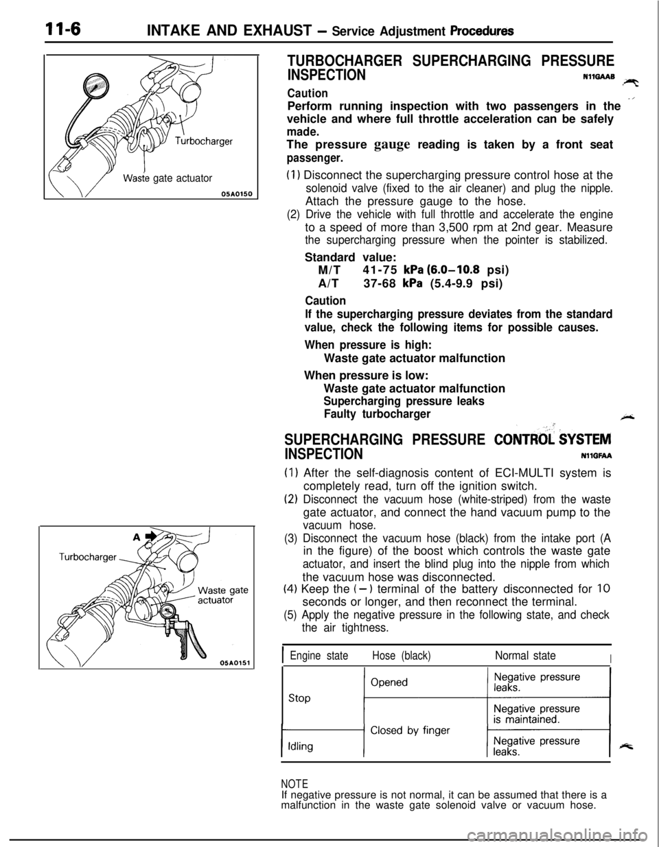
11-6INTAKE AND EXHAUST - Service Adjustment Procedwes
Wasie gate actuator05AOlSO
TURBOCHARGER SUPERCHARGING PRESSURE
INSPECTIONN1mAAB!PTCautionPerform running inspection with two passengers in the
-’vehicle and where full throttle acceleration can be safely
made.The pressure gauge reading is taken by a front seat
passenger.
(1) Disconnect the supercharging pressure control hose at the
solenoid valve (fixed to the air cleaner) and plug the nipple.Attach the pressure gauge to the hose.
(2) Drive the vehicle with full throttle and accelerate the engineto a speed of more than 3,500 rpm at
2nd gear. Measure
the supercharging pressure when the pointer is stabilized.Standard value:
M/T41-75
kPa (6.0-10.8 psi)
A/T37-68
kPa (5.4-9.9 psi)
Caution
If the supercharging pressure deviates from the standard
value, check the following items for possible causes.
When pressure is high:Waste gate actuator malfunction
When pressure is low:
Waste gate actuator malfunction
Supercharging pressure leaks
Faulty turbocharger
+-
SUPERCHARGING PRESSURE CONTRtd $YSTEM
INSPECTIONNllGFAA
(1) After the self-diagnosis content of ECI-MULTI system is
completely read, turn off the ignition switch.
(2) Disconnect the vacuum hose (white-striped) from the wastegate actuator, and connect the hand vacuum pump to the
vacuum hose.
(3) Disconnect the vacuum hose (black) from the intake port (Ain the figure) of the boost which controls the waste gate
actuator, and insert the blind plug into the nipple from whichthe vacuum hose was disconnected.
(4) Keep the (- ) terminal of the battery disconnected for 10seconds or longer, and then reconnect the terminal.
(5) Apply the negative pressure in the following state, and check
the air tightness.
IEngine stateHose (black)Normal stateI
stop ;“““*I
NOTEIf negative pressure is not normal, it can be assumed that there is a
malfunction in the waste gate solenoid valve or vacuum hose.
Page 429 of 1216
INTAKE AND EXHAUST - Service Adjustment ProceduresII-7
w05A0155
h61
NO06061
NO0616 I
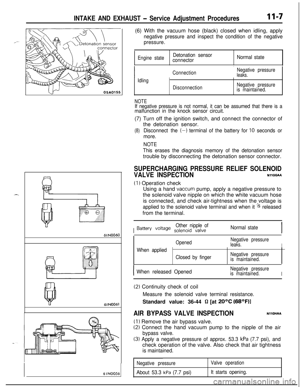
NO056(6) With the vacuum hose (black) closed when idling, apply
negative pressure and inspect the condition of the negative
pressure.
Engine stateDetonation sensor
connectorNormal state
,
ConnectionNegative pressureleaks.
Idling
DisconnectionNegative pressure
is maintained.
NOTEIf negative pressure is not normal, it can be assumed that there is amalfunction in the knock sensor circuit.(7) Turn off the ignition switch, and connect the connector of
the detonation sensor.
(8)Disconnect the (-) terminal of the battery for 10 seconds or
more.
NOTE
This erases the diagnosis memory of the detonation sensortrouble by disconnecting the detonation sensor connector.
SUPERCHARGING PRESSURE RELIEF SOLENOID
VALVE INSPECTIONNllGGAA
(1) Operation check
Using a hand
vaccum pump, apply a negative pressure to
the solenoid valve nipple on which the white vacuum hose
is connected, and check air-tightness when the voltage is
applied to the solenoid valve terminal and when it i‘s releasedfrom the terminal.
I
Other nipple ofBattery voile solenoid valveNormal state
OpenedNegative pressureleaks.IWhen applied
Closed by fingerNegative pressure
is maintained.
IWhen released OpenedNegative pressure
is maintained.
I
(2) Continuity check of coil
Measure the solenoid valve terminal resistance.Standard value: 36-44
fl [at 20°C (68OF)l
AIR BYPASS VALVE INSPECTIONNllGHAA
(1) Remove the air bypass valve.
(2) Connect the hand vacuum pump to the nipple of the air
bypass valve.
(3) Apply a negative pressure of approx. 53.3 kPa (7.7 psi), andcheck operation of the valve. Also check that air tightness
is maintained.
Negative pressure
About 53.3 kPa (7.7 psi)
Valve operation
It starts opening.
Page 440 of 1216
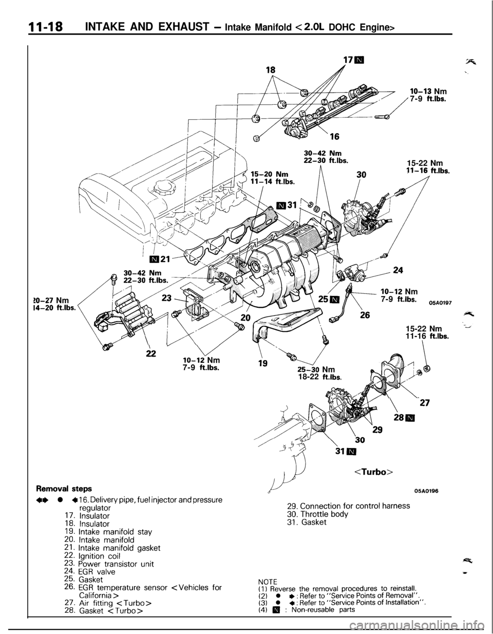
11-18INTAKE AND EXHAUST - Intake Manifold < 2.0L DOHC Engine>
10-27 Nm14-20 ft.lbs.
18hIO-13 Nm
7-9
ft.lbs.15-22 Nm11-16
ft.lbs.IO-12 Nm
7-9
ftlbs.05A0197
15-22 Nm
11-16
ftlbs.
wi2” vlo-12 Nm
7-9 ftlbs.25-30 Nm
18-22
ft.lbs.
24
\‘27
28lll
Removal steps
+e l + 16. Delivery pipe, fuel injector and pressureregulator17. Insulator18. Insulator19. Intake manifold stay
20. Intake manifold21. Intake manifold gasket22. Ignition coil23. Power transistor unit24. EGR valve25. Gasket26. EGR temperature sensor
29. Connection for control harness
30. Throttle body31. Gasket
NOTE(I) Reverse the removal procedures to reinstall.(2) l * : Refer to “Service Points of Removal”.(3) l + : Refer to “Service Points of Installation”.(4) 0 : Non-reusable parts
Page 458 of 1216
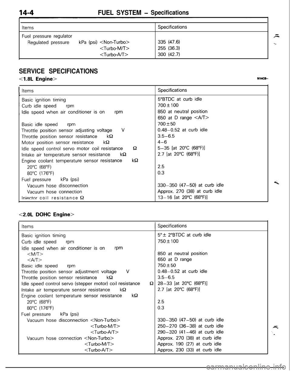
FUEL SYSTEM- Specifications
ItemsSpecifications
Fuel pressure regulator
Regulated pressurekPa (psi)
255 (36.3)
SERVICE SPECIFICATIONS
<1.8L Engine>N14CB-
ItemsSpecifications
Basic ignition timing~
Curb idle speedvm
, Idle speed when air conditioner is onrpm
Basic idle speedwm
Throttle position sensor adjusting voltageV
Throttle position sensor resistancekQMotor position
sensor resistancek&
Idle speed control servo motor coil resistance
Intake air temperature sensor resistancekQ
Engine coolant temperature sensor resistance
20°C (68°F)
80°C (176°F)
Fuel pressurekPa (psi)
Vacuum hose disconnection
Vacuum hose connection
Iniectnr coil resistance Q
52
k8
5”BTDC at curb idle
700f 100
850 at neutral position
650 at D range
700 f 50
0.48-0.52 at curb idle
3.5-6.5
4-6
5-35 [at 20°C (68”F)l
2.7 [at 20°C (68”F)I
2.5
0.3
330-350 (47-50) at curb idleApprox.
270 (38) at curb idle
13-16 [at 20°C (68”F)l
<2.0L DOHC Engine>
Items( Specifications
Basic ignition timing
Curb idle speedrpm
Idle speed when air conditioner is onrpm
al-r>
Basic idle speedrpm
Throttle position sensor adjustment voltageVThrottle position
sensor resistancekQ
Idle speed control servo (stepper motor) coil resistance
Intake air temperature sensor resistancekQ
Engine coolant temperature sensor resistancek0
20°C (68°F)
80°C (176°F)
Fuel pressurekPa (psi)
Vacuum hose disconnection
Vacuum hose connection
Q
5”+ 2”BTDC at curb idle
750+ 100
850 at neutral position
650 at D range
750 f 50
0.48-0.52 at curb idle
3.5-6.5
28-33 [at 20°C (68”F)l
2.7 [at 20°C (68”F)I
2.5
0.3
330-350 (47-50) at curb idle
250-270 (36-38) at curb idle
290-320 (41-46) at curb idleApprox.
270 (38) at curb idle
Approx. 190 (27) at curb idle
Approx. 230 (33) at curb idle
Page 460 of 1216
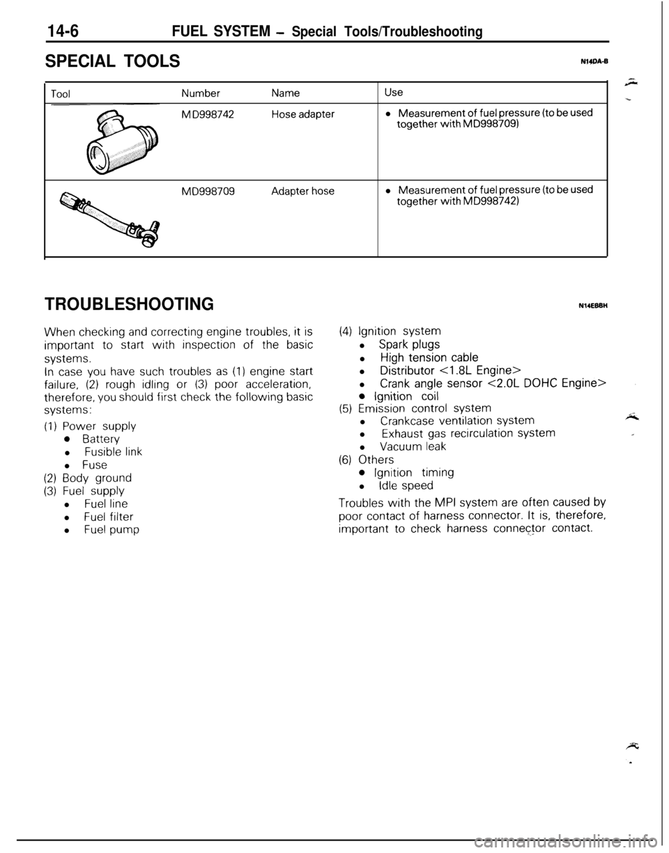
14-6FUEL SYSTEM - Special Tools/Troubleshooting
SPECIAL TOOLSNWA-B
Number
M D998742
Name
Hose adapter
Usel Measurement
of fuel pressure (to be usedtogether
with MD9987091
MD998709Adapter hosel Measurement of fuel pressure (to be usedtogether
with MD9987421
TROUBLESHOOTING
When checking and correcting engine troubles, it is
important to start with inspection of the basic
systems.
In case you have such troubles as (1) engine start
failure, (2) rough idling or (3) poor acceleration,
therefore, you should first check the following basic
systems:
(1) Power supply
0 Batteryl
Fusible linkl
Fuse
(2) Body ground
(3) Fuel supplyl
Fuel linel
Fuel filter
l
Fuel pump
N14EBBH
(4) Ignition systeml
Spark plugsl
High tension cablel Distributor
<1.8L Engine>
l
Crank angle sensor <2.0L DOHC Engine>
0 Ignition coil
(5) Emission control systeml
Crankcase ventilation systeml
Exhaust gas recirculation systeml
Vacuum leak
(6) Others
0 Ignition timing
l
Idle speed
Troubles with the MPI system are often caused by
poor contact of harness connector. It is, therefore,
important to check harness connector contact.
Page 461 of 1216
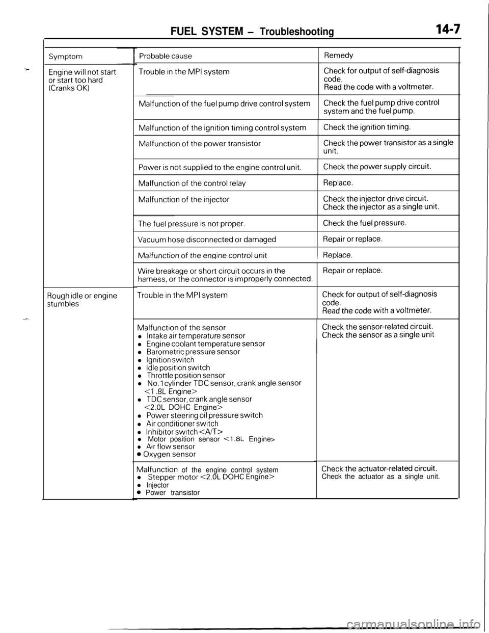
FUEL SYSTEM - Troubleshooting14-7
Symptom
Engine will not startor start too hard(Cranks OK)
Rough idle or engine
stumbles
Trouble in the MPI systemCheck for output of self-diagnosis
code.Read the code with a voltmeter.Malfunction
of the fuel pump drive control systemCheck the fuel pump drive controlsystem
and the fuel pump.Malfunction
of the ignition timing control systemMalfunction
of the power transistor
Check the ignition timing.
Check the power transistor as a single
unit.
Power is not supplied to the engine control unit.Check the power supply circuit.Malfunction
of the control relayMalfunction
of the injector
Replace.
Check the injector drive circuit.
Check the injector as a single unit.
The fuel pressure is not proper.Check the fuel pressure.
I
Vacuum hose disconnected or damagedRepair or replace.IMalfunction of
the engine control unit) Replace.
Wire breakage or short circuit occurs in theRepair or replace.
harness, or the connector is improperly connected.
Trouble in the MPI systemCheck for output of self-diagnosis
code.Read the code with a voltmeter.Malfunction
of the sensor
l Intake air temperature sensor
Check the sensor-related circuit.
Check the sensor as a single unit
Probable causeRemedy
l Engine coolant temperature sensorl Barometric pressure sensor
l Ignition switchl Idle position switchl Throttle position sensorl No. 1 cylinder TDC sensor, crank angle sensor
l TDC sensor, crank angle sensor<2.0L DOHC Engine>
l Power steering oil pressure switch
l Air conditioner switch
l Inhibitor switch l Motor position sensor <1.8L Engine>l Air flow sensor0 Oxygen sensorMalfunction of the engine control system
l
Stepper motor <2.0L DOHC Engine>l Injector0 Power transistor
Check the actuator-related circuit.Check the actuator as a single unit.
Page 462 of 1216
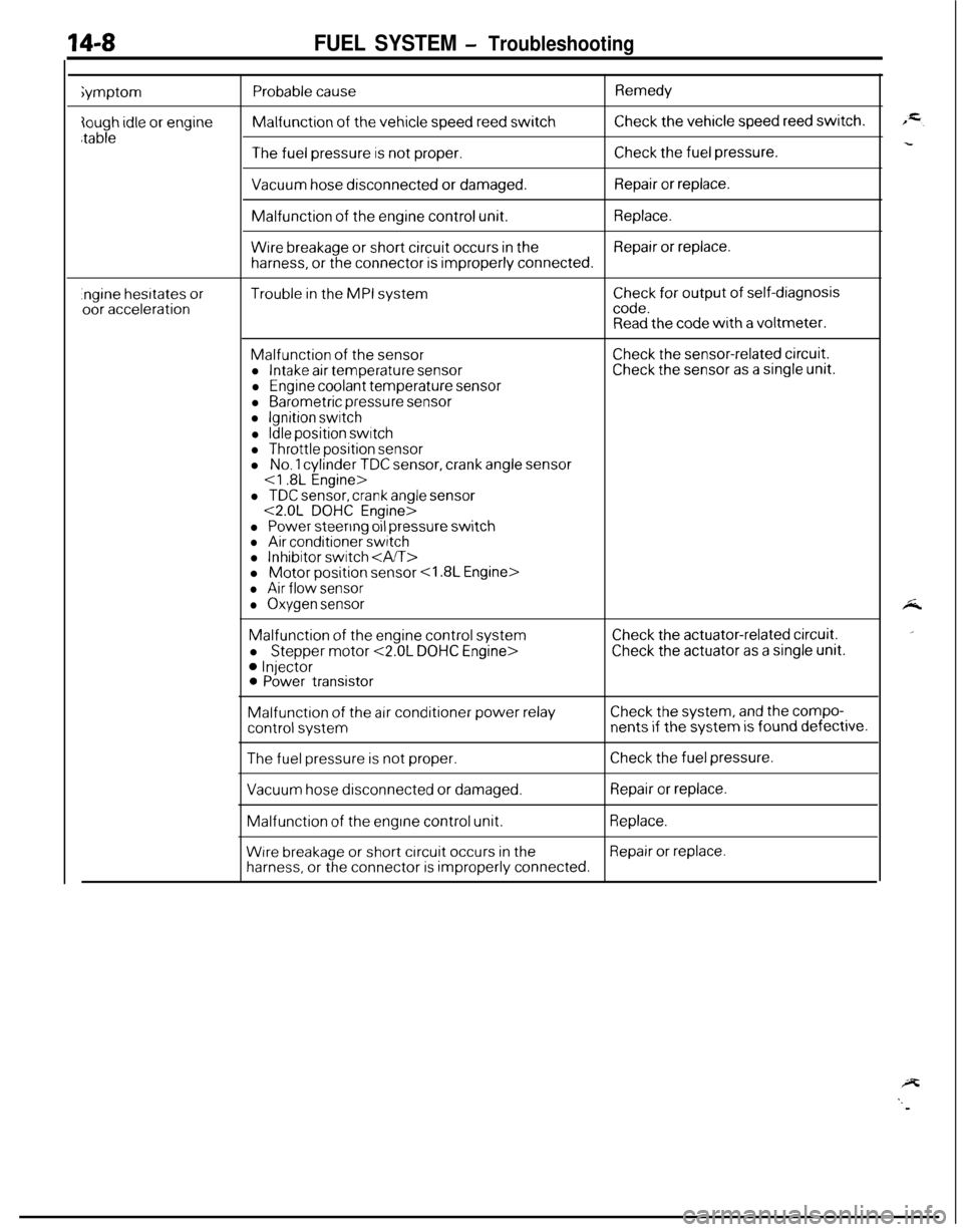
14-8FUEL SYSTEM - Troubleshootingiymptom
Probable causeMalfunction
of the vehicle speed reed switch
Remedy
Check the vehicle speed reed switch.
The fuel pressure is not proper.Check the fuel pressure.
Vacuum hose disconnected or damaged.Repair or replace.Malfunction
of the engine control unit.Replace.
Wire breakage or short circuit occurs in theRepair or replace.
harness, or the connector is improperly connected.
.ngine hesrtates oroor accelerationTrouble in the MPI systemCheck for output of self-diagnosiscode.Read the code with a voltmeter.
Malfunction of the sensorl Intake air temperature sensor
l Engine coolant temperature sensor
l Barometric pressure sensorl Ignition switch
l Idle position switchl Throttle position sensor
Check the sensor-related circuit.Check the sensor as a single unit.l
No. 1 cylinder TDC sensor, crank angle sensor
l TDC sensor, crank angle sensor<2.0L DOHC Engine>
l Power steering oil pressure switchl Air conditioner switchl Inhibitor switch l Motor position sensor
l Air flow sensor
l Oxygen sensorMalfunction
of the engine control system
l
Stepper motor <2.0L DOHC Engine>
0 Injector0 Power transistor
Check the actuator-related circuit.
Check the actuator as a single unit.Malfunction
of the air conditioner power relayCheck the system, and the compo-
control systemnents if the system is found defective.
The fuel pressure is not proper.Check the fuel pressure.
Vacuum hose disconnected or damaged.Repair or replace.Malfunction
of the engine control unit.Replace.
Wrre breakage or short circuit occurs in theRepair or replace.
harness, or the connector is improperly connected.
Page 463 of 1216
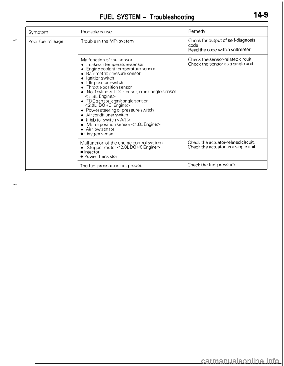
FUEL SYSTEM - Troubleshooting14-S
Symptom
Poor fuel mileage,
Probable cause
Trouble In the MPI system
Remedy
Check for output of self-diagnosis
code.Read the code with a voltmeter.Malfunction
of the sensorl Intake air temperature sensorl Engine coolant temperature sensorl Barometric pressure sensorl Ignition switchl Idle position switch
l Throttle position sensorl No. 1 cylinder TDC sensor, crank angle sensor
Check the sensor-related circuit.Check the sensor as a single unit.
l TDC sensor, crank angle sensor<2.0L DOHC Engine>
l Power steering oil pressure switch
l Air conditioner switch
l lnhrbrtor switch l Motor
position sensor
l Air flow sensor
0 Oxygen sensor
Malfunction of the engine control system
l Stepper motor <2.0L DOHC Engine>
0 Injector0 Power transistor
Check the actuator-related circurt.Check the actuator as a single unit.
The fuel pressure is not proper.Check the fuel pressure.