ignition MITSUBISHI ECLIPSE 1991 Owner's Manual
[x] Cancel search | Manufacturer: MITSUBISHI, Model Year: 1991, Model line: ECLIPSE, Model: MITSUBISHI ECLIPSE 1991Pages: 1216, PDF Size: 67.42 MB
Page 172 of 1216
![MITSUBISHI ECLIPSE 1991 Owners Manual 5-32BRAKES -Anti-lock Braking System Troubleshooting
CABS warning light does not illuminate when ignition key is in “START” position.
[Explanation]The ABS ECU uses the
IG2 power source which isan MITSUBISHI ECLIPSE 1991 Owners Manual 5-32BRAKES -Anti-lock Braking System Troubleshooting
CABS warning light does not illuminate when ignition key is in “START” position.
[Explanation]The ABS ECU uses the
IG2 power source which isan](/img/19/57104/w960_57104-171.png)
5-32BRAKES -Anti-lock Braking System Troubleshooting
CABS warning light does not illuminate when ignition key is in “START” position.
[Explanation]The ABS ECU uses the
IG2 power source which isand the ECU turns the valve relay OFF. If the
turned off in the “START” position. The ABSwarning light does not illuminate at this time, there
warning light uses the
IGI power source which isis trouble in the warning light circuit on the valve
not turned off even in the “START” position.relay side.
Consequently, in the “START” position, power is off
MAINIGNITIONFUSIBLESWITCHLINK @I(IGl)J/B
“62
I .1411213141516l7l61911112113114115U6i,79
@COMBINATIONAL METER
“58ABS ECU
1410000
hydraulicunit (HU) connector and
>\/I
1With the ignition key in the
“ON” position, does voltage
between body connector
terminal No.8 and ground
indicate the battery voltage?
Is there continuity between
No~Broken line between HU
body connector terminaland body groundNo.9 and ground?
I
YesIs there continuity between
HU connector terminal No. 8and terminal
No.9?
YesRemove the valve relay. Is
there continuity between
terminal No. 87a and No. 30?
I
Yes1 Replace valve relay.
HU harness malfunction
I
1 Replace HU.
Page 173 of 1216
BRAKES - Anti-lock Braking System Troubleshooting5-33
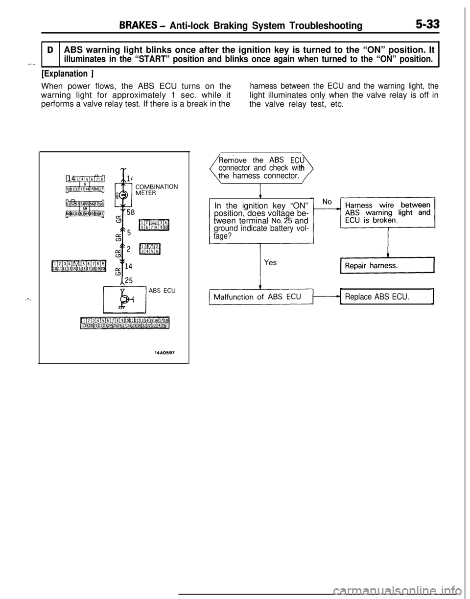
DABS warning light blinks once after the ignition key is turned to the “ON” position. It
illuminates in the “START” position and blinks once again when turned to the “ON” position.*-_
[Explanation ]When power flows, the ABS ECU turns on the
harness between the ECU and the warning light, thewarning light for approximately 1 sec. while itlight illuminates only when the valve relay is off in
performs a valve relay test. If there is a break in the
the valve relay test, etc.
Y
x %l4
9
4
n. 58
ABS ECU
14A0597
EC
4connector and check with
he harness connector. /\/
IIn the ignition key “ON”
position, does voltage be-
tween terminal
No.25 andground indicate battery vol-
tage?
Replace ABS ECU.I
Page 176 of 1216
![MITSUBISHI ECLIPSE 1991 Owners Manual 5-36BRAKES - Anti-lock Braking System Troubleshooting
E-3Abnormality of G sensor circuit
[Explanation]The ABS ECU turns on the warning light in the
following cases.
lOFF trouble turning G sensor OFF ( MITSUBISHI ECLIPSE 1991 Owners Manual 5-36BRAKES - Anti-lock Braking System Troubleshooting
E-3Abnormality of G sensor circuit
[Explanation]The ABS ECU turns on the warning light in the
following cases.
lOFF trouble turning G sensor OFF (](/img/19/57104/w960_57104-175.png)
5-36BRAKES - Anti-lock Braking System Troubleshooting
E-3Abnormality of G sensor circuit
[Explanation]The ABS ECU turns on the warning light in the
following cases.
lOFF trouble turning G sensor OFF (It is judged
that the
G sensor continues to be OFF for more
than approximately 13 seconds except when the
lWhen there is a broken wire or short circuit in
the harness for the
G sensor system.
PlUN; F;SIBLEIGNITIONSWITCH (IG2)J/B
G-SENSOR
E-lABSECU
14AO609
Is G sensor normal? (ReferNoto
P.5-86.)Replace G sensor.
I YesWith the ignition key “ON”
_ No m The harness between the
does the voltage betweenG sensor and the ABS
terminal No.6 and groundECU is broken.
indicate battery voltage?
IG sensor circuit is normal.I
Page 178 of 1216
![MITSUBISHI ECLIPSE 1991 Owners Manual 5-38BRAKES - Anti-lock Braking System Troubleshooting
E-5Abnormality of solenoid valve drive circuit
[Explanation]*>The ABS ECU normally monitors the solenoid valve
when turned OFF, the ECU determines MITSUBISHI ECLIPSE 1991 Owners Manual 5-38BRAKES - Anti-lock Braking System Troubleshooting
E-5Abnormality of solenoid valve drive circuit
[Explanation]*>The ABS ECU normally monitors the solenoid valve
when turned OFF, the ECU determines](/img/19/57104/w960_57104-177.png)
5-38BRAKES - Anti-lock Braking System Troubleshooting
E-5Abnormality of solenoid valve drive circuit
[Explanation]*>The ABS ECU normally monitors the solenoid valve
when turned OFF, the ECU determines the solenoid%’ -’drive circuit.coil wire is broken/short circuited or the harness is
If no current flows in the solenoid even if the ECUbroken/short circuited and then the warning light
turns the solenoid ON or if it continues to flow evenlights up.
IGNITIONSWITCH(IGI)
7JIB------_-_tor and check with the
side connector.
Connect HU
1OP connec-
disconnect ECU con-
>Is the solenoid valve resis-
tance value within the range
of the standard values when
measured at the ECU con-
nector?Standard value:
3.0-3.2 Q
Yes1
II
I
Solenoid valve drive circuit isnormal.I
NoReplace HU.I
NoIs the resistance value for
the solenoid valve within the
range ofthe standard
values?Standard value:
3.0-3.2 Q, IYes ,
1
JThe harness wire for the
solenoidvalvecircuit
whose resistance value is
outside the range of the
standard value is broken
or short circuited.,-‘he-
-Repair
Page 179 of 1216
![MITSUBISHI ECLIPSE 1991 Owners Manual BRAKES - Anti-lock Braking System Troubleshooting5-39
E-6Abnormality of valve relay drive circuitI
j-a [Explanation]When the ignition switch is turned ON, the ABSnormal. In addition, normally it monit MITSUBISHI ECLIPSE 1991 Owners Manual BRAKES - Anti-lock Braking System Troubleshooting5-39
E-6Abnormality of valve relay drive circuitI
j-a [Explanation]When the ignition switch is turned ON, the ABSnormal. In addition, normally it monit](/img/19/57104/w960_57104-178.png)
BRAKES - Anti-lock Braking System Troubleshooting5-39
E-6Abnormality of valve relay drive circuitI
j-a [Explanation]When the ignition switch is turned ON, the ABSnormal. In addition, normally it monitors whether or
ECU switches the valve relay OFF and ON for annot there is power in the valve power monitor line
initial check, compares the voltage of the signal tosince the valve relay is normally ON. Then, if the
the valve relay and valve power monitor line voltagesupply of power to the valve power monitor line is
to check whether the valve relay operation is
interrupted, the warning light illuminates.
IGNITIONMAIN FUSIBLESWITCHLINK @W-31)When the valve relay is
checked, are the followingconditions found?No.85-No.86:resistancevalue 60-120 Q
No.30-No.87a: continuityNo.30-No.87: No continui-
When battery voltage is ap-plied between terminals
No.86 and No. 85 grounded.
No. 30-No. 87: continuity
No.
30-No. 87a: no continui-
tyremove the HU connec-
NoValve relay malfunction
Replace valve relay.
IConnect the HU
remove the ECU con-
I Yes
IValve relay drive circuit isnormal.I
Page 255 of 1216
COOLING - Troubleshooting7A7
OPERATION
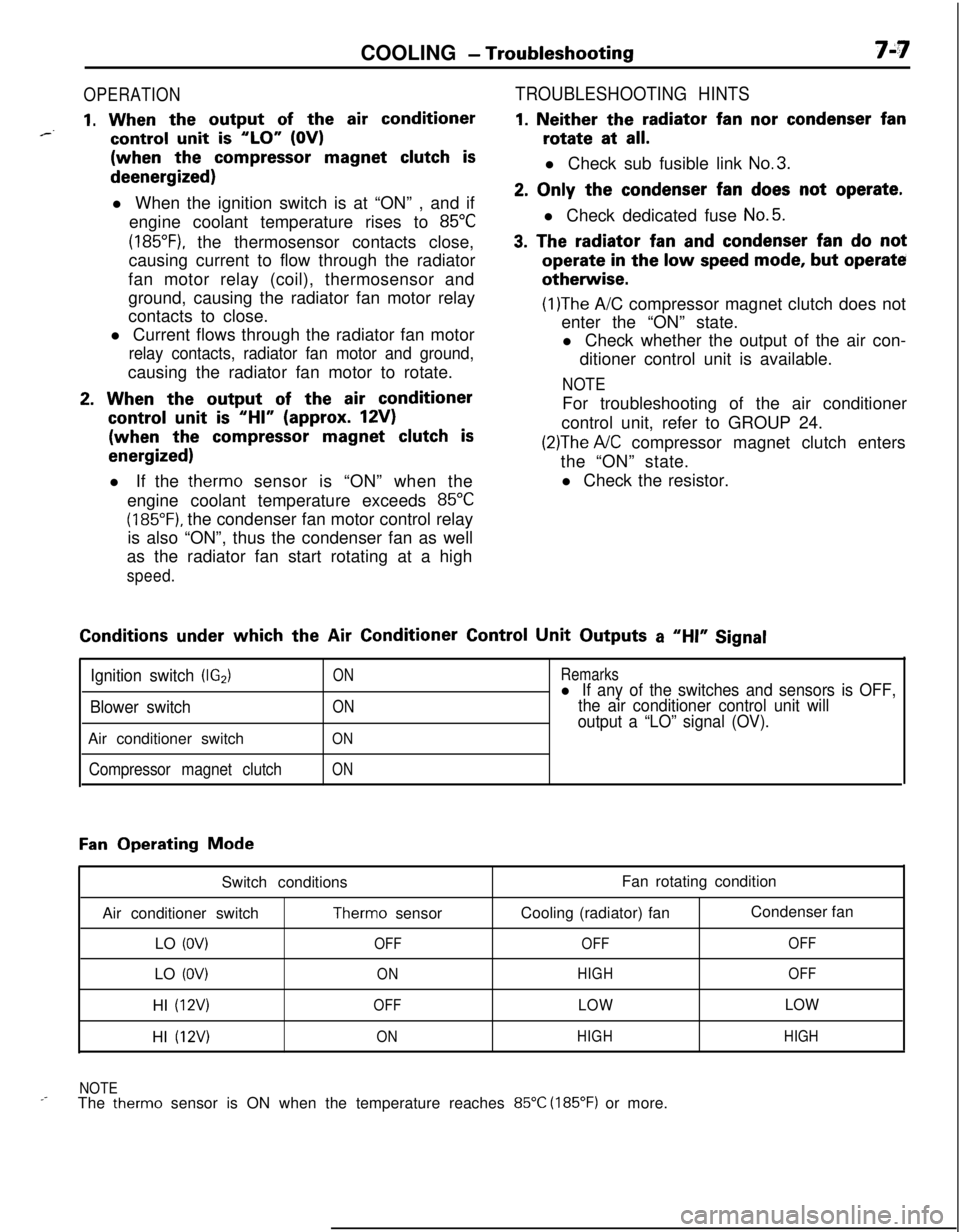
1. When the output of the air conditioner*--control unit is “LO” (OV)(when the
compressor magnet clutch isdeenergized)
l When the ignition switch is at “ON” , and if
engine coolant temperature rises to
85°C
(185”F), the thermosensor contacts close,
causing current to flow through the radiator
fan motor relay (coil), thermosensor and
ground, causing the radiator fan motor relay
contacts to close.
l Current flows through the radiator fan motor
relay contacts, radiator fan motor and ground,causing the radiator fan motor to rotate.
2. When the output of the air conditioner
control unit is “HI” (approx. 12V)(when the
compressor magnet clutch is
energized)l If the therm0 sensor is “ON” when the
engine coolant temperature exceeds
85°C
(185°F). the condenser fan motor control relay
is also “ON”, thus the condenser fan as well
as the radiator fan start rotating at a high
speed.
TROUBLESHOOTING HINTS
1. Neither the radiator fan nor condenser fanrotate at
all.l Check sub fusible link
No.3.
2. Only the condenser fan does not operate.l Check dedicated fuse
No.5.
3. The radiator fan and condenser fan do notoperate
in the low speed mode, but operateotherwise.
(1)The A/C compressor magnet clutch does not
enter the “ON” state.
l Check whether the output of the air con-
ditioner control unit is available.
NOTEFor troubleshooting of the air conditioner
control unit, refer to GROUP 24.
(2)The A/C compressor magnet clutch enters
the “ON” state.
l Check the resistor.Conditions
under which the Air Conditioner Control Unit Outputs a “HI” Signal
Ignition switch (IG2)
Blower switchAir conditioner switch
Compressor magnet clutch
ON
ON
ON
ON
Remarksl If any of the switches and sensors is OFF,
the air conditioner control unit will
output a “LO” signal (OV).
Fan Operating Mode
Switch conditions
Air conditioner switch
Therm0 sensor
LO
(OV)OFFLO
(OV)ONHI
(12V)OFFHI
(12V)ONFan rotating condition
Cooling (radiator) fanCondenser fan
OFFOFF
HIGHOFF
LOWLOW
HIGHHIGH
NOTE
_-The therm0 sensor is ON when the temperature reaches 85°C (185°F) or more.
Page 309 of 1216
ENGINE <1.8L Engine>- Service Adjustment Procedures9-25
MANIFOLD VACUUM INSPECTION(1) Before inspection and adjustment, put the vehicle
in=following state.
l Engine coolant temperature:
85-95°C (185-205°F)
l Lights, electric, cooling fan, and accessories: OFF
lTransaxle: Neutral
(N or P for vehicles with an automa-
tic transaxle)
l Steering wheel: Neutral position
(2) Check that the idling revolution speed is normal.
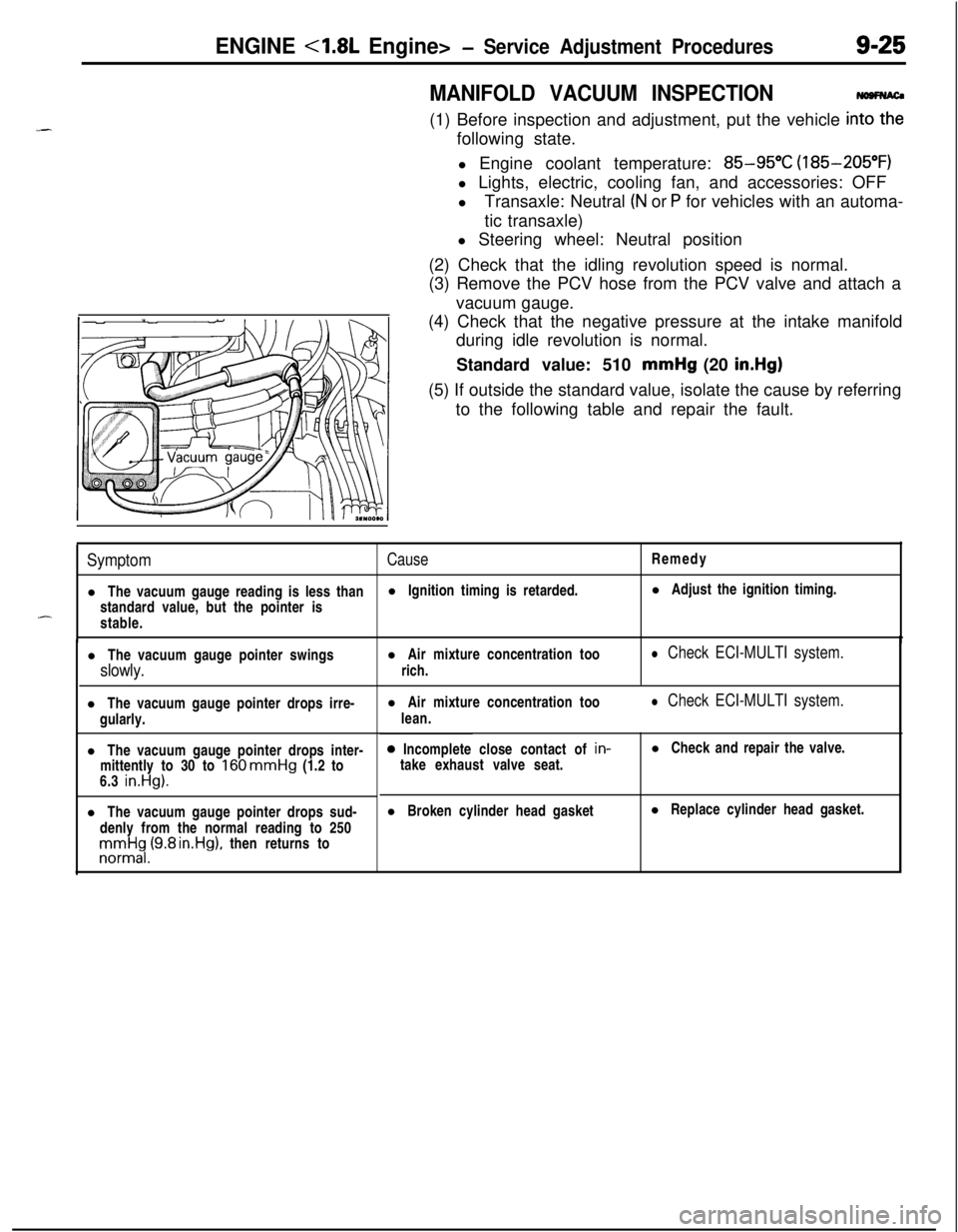
(3) Remove the PCV hose from the PCV valve and attach a
vacuum gauge.
(4) Check that the negative pressure at the intake manifold
during idle revolution is normal.
Standard value: 510 mmHg (20
in.Hg)(5) If outside the standard value, isolate the cause by referring
to the following table and repair the fault.
SymptomCauseRemedy
l The vacuum gauge reading is less thanl Ignition timing is retarded.l Adjust the ignition timing.
standard value, but the pointer is
-stable.
l The vacuum gauge pointer swingsl Air mixture concentration too
slowly.rich.
l Check ECI-MULTI system.l The vacuum gauge pointer drops irre-
gularly.
l The vacuum gauge pointer drops inter-
mittently to 30 to
160 mmHg (1.2 to
6.3 in.Hg).l The vacuum gauge pointer drops sud-
denly from the normal reading to 250rronnrt$,(9.8 rn.Hg), then returns tol Air mixture concentration too
lean.
l Check ECI-MULTI system.0 Incomplete close contact of in-
take exhaust valve seat.l Check and repair the valve.
l Broken cylinder head gasketl Replace cylinder head gasket.
Page 359 of 1216
_-
a--ENGINE
<2.0L DOHC Engine> -Service Adjustment Procedures9-75
JMANIFOLD VACUUM INSPECTION
NO9FNAO(1) Before inspection and adjustment, put the vehicle into the
following state.
l Engine coolant temperature:
85-g5”C (185-205°F)
l Lights, electric, cooling fan, and accessories: OFF
lTransaxle: Neutral (N or
P for vehicles with an automa-
tic transaxle)
l Steering wheel: Neutral position
(2) Check that the idling revolution speed is normal.
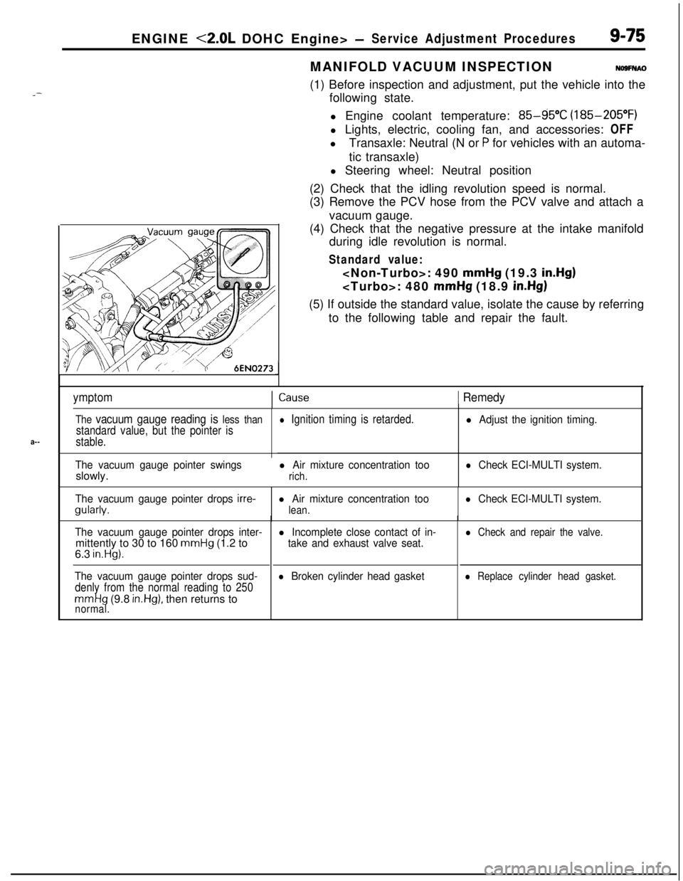
(3) Remove the PCV hose from the PCV valve and attach a
vacuum gauge.
(4) Check that the negative pressure at the intake manifold
during idle revolution is normal.
Standard value:
mmHg (19.3 in.Hg)
mmHg (18.9 in.Hg)(5) If outside the standard value, isolate the cause by referring
to the following table and repair the fault.
ymptomICause1 Remedy
The vacuum gauge reading is less than
standard value, but the pointer is
stable.
The vacuum gauge pointer swingsslowly.
l Ignition timing is retarded.
l Air mixture concentration too
rich.
l Adjust the ignition timing.
l Check ECI-MULTI system.
The vacuum gauge pointer drops
irre-gularly.l Air mixture concentration too
lean.
l Check ECI-MULTI system.
The vacuum gauge pointer drops inter-mittently to 30 to 160
mmHg (1.2 to
6.3 in.Hg).
The vacuum gauge pointer drops sud-
denly from the normal reading to 250
mmHg (9.8 in.Hg), then returns tonormal.
l Incomplete close contact of in-
take and exhaust valve seat.
l Broken cylinder head gasket
l Check and repair the valve.
l Replace cylinder head gasket.
Page 365 of 1216
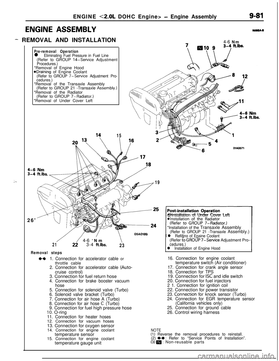
ENGINE <2.0L DOHC Engine> - Engine Assembly
ENGINE ASSEMBLY
- REMOVAL AND INSTALLATION
;-
Pre-removal Operationl Eliminating Fuel Pressure in Fuel Line(Refer to GROUP 14-Service AdjustmentProcedures.)*Removal of Engine Hood
@Draining of Engine Coolant(Refer to GROUP 7-Service Adjustment Pro-
cedures.)*Removal of the Transaxle Assembly
(Refer to GROUP 21 -Transaxle Assembly.)
*Removal of the Radiator
(Refer to GROUP 7-Radiator.)
*Removal of Under Cover Left
26'
15
I4-6 Nm\I /MAO571
19@Installation of Under Cover Left
*Installation of the Transaxle Assembly
(Refer to GROUP 21 -Transaxle Assembly.)
I l Refilling of Enaine Coolant
/22/ 4-6 ‘Nm\213-4 ftlbs.23
Removal steps
~~1. Connection for accelerator cable orthrottle cable
2. Connection for accelerator cable (Auto-
cruise control)3. Connection for fuel return hose
4. Connection for brake booster vacuum
hose
5. Connection for solenoid valve (Turbo)
6. Solenoid valve bracket (Turbo)
7. Connection for air hose A (Turbo)
8. Connection for air hose
C (Turbo)9. Connection for fuel high pressure hose
10. O-ring11. Connection for heater hoses12. Connection for vacuum hoses
13. Connection for oxygen sensor
14. Connection for engine coolant
temperature sensor
15. Connection for engine coolant
temperature gauge unit(Refer
t’o GROUP 7-Service Adjustment Pro-cedures.)l Installation of Engine Hood‘I
16. Connection for engine coolanttemperature switch (Air conditioner)
17. Connection for crank angle sensor
18. Connection for TPS19. Connection for
ISC and idle switch
20. Connection for fuel injectors
2 1. Connection for ignition coil22. Connection for power transistor
23. Connection for knock sensor (Turbo)
24. Connection for EGR temperature sensor
(California vehicles only)
25. Connection for ground cable26. Control wiring harness
NOTE(I) Reverse the removal procedures to reinstall.
(2) e+ : Refer to “Service Points of Installation”.(3) m : Non-reusable parts
Page 370 of 1216
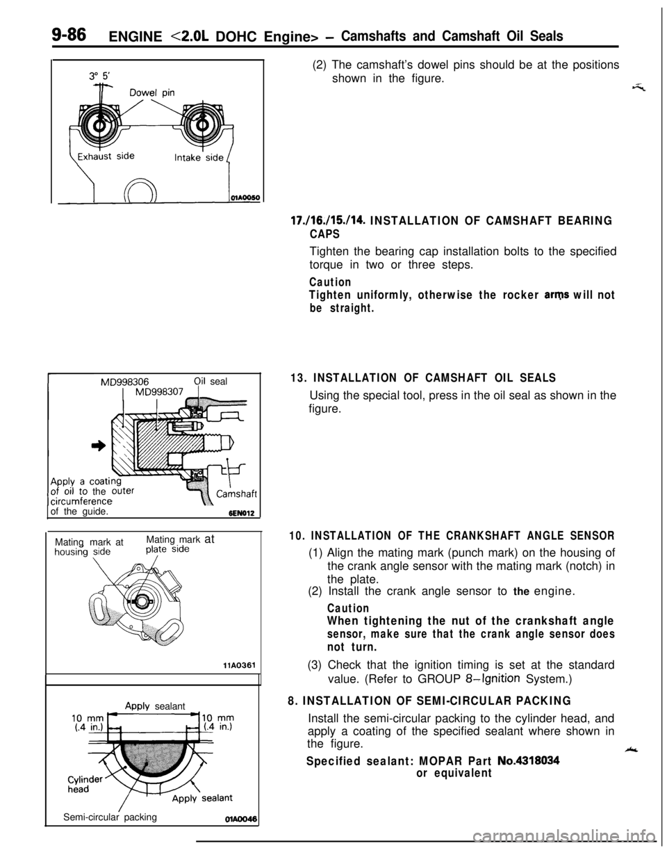
9-86ENGINE <2.0L DOHC Engine> -Camshafts and Camshaft Oil Seals
rMD998306qil seal
coatithe
mrenceof the guide.
6EN612Matingmark atMating mark at
llA0361Semi-circular packing
Awlv sealant(2) The camshaft’s dowel pins should be at the positions
shown in the figure.
17./16./15./14. INSTALLATION OF CAMSHAFT BEARING
CAPSTighten the bearing cap installation bolts to the specified
torque in two or three steps.
Caution
Tighten uniformly, otherwise the rocker arms will not
be straight.
13. INSTALLATION OF CAMSHAFT OIL SEALSUsing the special tool, press in the oil seal as shown in the
figure.
_-‘7
10. INSTALLATION OF THE CRANKSHAFT ANGLE SENSOR(1) Align the mating mark (punch mark) on the housing of
the crank angle sensor with the mating mark (notch) in
the plate.
(2) Install the crank angle sensor to the engine.
Caution
When tightening the nut of the crankshaft angle
sensor, make sure that the crank angle sensor does
not turn.(3) Check that the ignition timing is set at the standard
value. (Refer to GROUP
8-Ignition System.)
8. INSTALLATION OF SEMI-CIRCULAR PACKINGInstall the semi-circular packing to the cylinder head, and
apply a coating of the specified sealant where shown in
the figure.
Ak
Specified sealant: MOPAR Part No.4318034
or equivalent