heater MITSUBISHI ECLIPSE 1991 Workshop Manual
[x] Cancel search | Manufacturer: MITSUBISHI, Model Year: 1991, Model line: ECLIPSE, Model: MITSUBISHI ECLIPSE 1991Pages: 1216, PDF Size: 67.42 MB
Page 1171 of 1216
HEATERS AND AIR CONDITIONING - Heater Control Assembly24-27
lQA0274
20A0408
SERVICE POINTS OF REMOVALN24GBAL
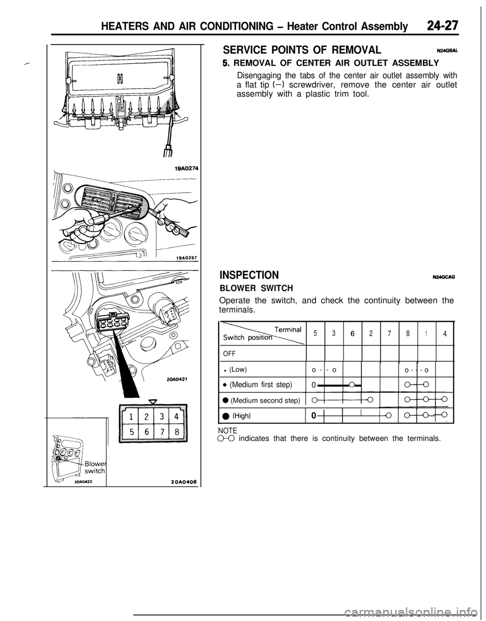
5. REMOVAL OF CENTER AIR OUTLET ASSEMBLY
Disengaging the tabs of the center air outlet assembly witha flat tip (-1 screwdriver, remove the center air outlet
assembly with a plastic trim tool.
INSPECTION
BLOWER SWITCHN24GCAG
Operate the switch, and check the continuity between the
terminals.
Termina’53627814
OFFl (Low)
o--o
o---o
o (Medium first step)0f-le-0
0 (Medium second step)0-0
0 (High)0 1I
Ilo oln
NOTED0 indicates that there is continuity between the terminals.
Page 1172 of 1216
24-28HEATERS AND AIR CONDITIONING - Heater Control Assembly
II
IT20AO409
SERVICE POINTS OF INSTALLATIONN24GOAO
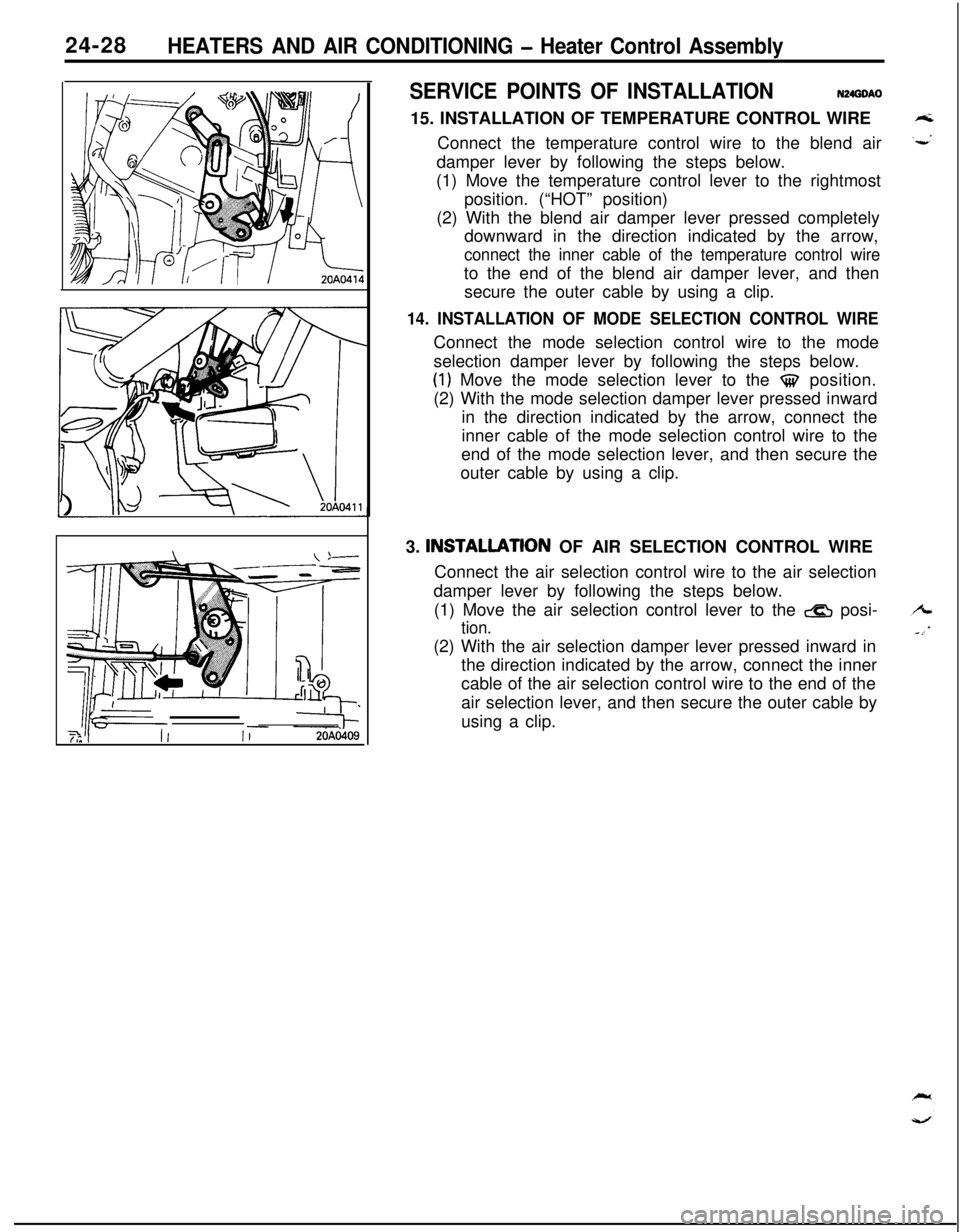
15. INSTALLATION OF TEMPERATURE CONTROL WIRE
Connect the temperature control wire to the blend air
damper lever by following the steps below.
(1) Move the temperature control lever to the rightmost
position. (“HOT” position)
(2) With the blend air damper lever pressed completely
downward in the direction indicated by the arrow,
connect the inner cable of the temperature control wireto the end of the blend air damper lever, and then
secure the outer cable by using a clip.
14. INSTALLATION OF MODE SELECTION CONTROL WIREConnect the mode selection control wire to the mode
selection damper lever by following the steps below.
(1) Move the mode selection lever to the $$ position.
(2) With the mode selection damper lever pressed inward
in the direction indicated by the arrow, connect the
inner cable of the mode selection control wire to the
end of the mode selection lever, and then secure the
outer cable by using a clip.
3. INSTALLATlON OF AIR SELECTION CONTROL WIRE
Connect the air selection control wire to the air selection
damper lever by following the steps below.
(1) Move the air selection control lever to the
& posi-
tion.(2) With the air selection damper lever pressed inward in
the direction indicated by the arrow, connect the inner
cable of the air selection control wire to the end of the
air selection lever, and then secure the outer cable by
using a clip.
Page 1173 of 1216
HEATERS AND AIR CONDITIONING - Resistor
RESISTOR
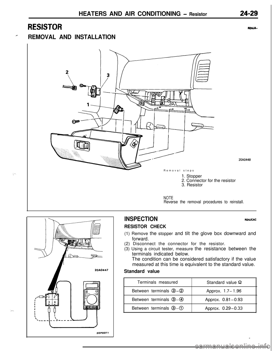
rREMOVAL AND INSTALLATIONRemoval steps
20A0447
1. Stopper
2. Connector for the resistor
3. Resistor
NOTEReverse the removal procedures to reinstall.
INSPECTION
RESISTOR CHECK
N2UCAC(1) Remove the stopper and tilt the glove box downward and
forward.(2) Disconnect the connector for the resistor.
(3) Using a circuit tester, measure the resistance between the
terminals indicated below.
The condition can be considered satisfactory if the value
measured at this time is equivalent to the standard value.
Standard value
Terminals measuredStandard value PBetween terminals
O-0Approx. 1.7- ‘I .96Between terminals @-@I
Approx.
0.81-0.93Between terminals
0-0Approx. 0.29-0.33
20A0448
Page 1174 of 1216
24-30HEATERS AND AIR CONDITIONING - Air Conditioner SwitchAIR CONDITIONER SWITCH
REMOVAL AND--N24OA..INSTALLATION
-2OAO419al Operationof
R;tdio and TanePlaver@Removal -..--._ _.-.-, -Removal steps
I. Air conditioner switch connectorCL7 Air rnnditinner switch
l Installation of Radio and Tape Player(Refer to GROUP 8-Audio System.)
NOTEOperation /Reverse
removal orocedures to reinstall.
I
77-. , .,a -.,a ,-,..-,.-. -.....,. ,.._._.__ _..- .-...-.-.r----- --
-----A
20A0427
20A0199
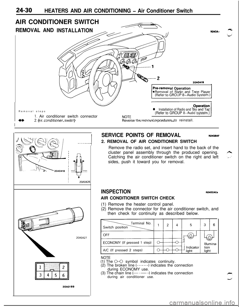
SERVICE POINTS OF REMOVALN24QBAF2. REMOVAL OF AIR CONDITIONER SWITCH
Remove the radio set, and insert hand to the back of the
cluster panel assembly through the produced opening.
Catching the air conditioner switch on the right and left
sides, push it toward you for removal.
INSPECTIONN24OCACaAIR CONDITIONER SWITCH CHECK
(1) Remove the heater control panel.
(2) Remove the connector for the air conditioner switch, and
then check for continuity as described below.
NOTE(1) The 0-0 symbol indicates continuity.
(2) The broken line (-----) indicates the connection
during ECONOMY use.
(3) The chain line
(- -----) indicates the connection
during air conditioner use.
Page 1175 of 1216
HEATERS AND AIR CONDITIONING - Heater Unit24-31
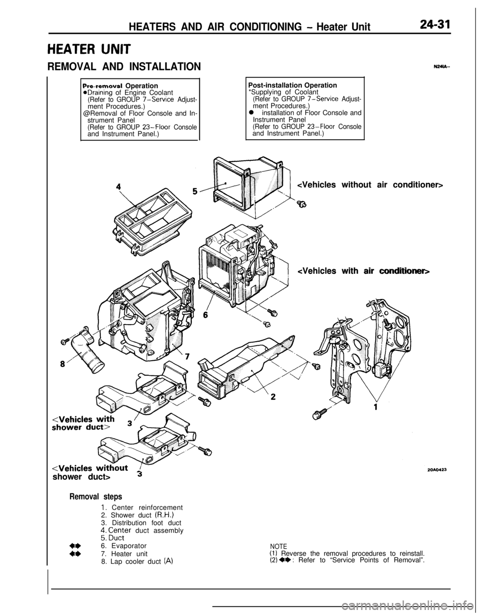
HEATER UNIT
REMOVAL AND INSTALLATIONN24m-
Pre-removal OperationeDraining of Engine Coolant(Refer to GROUP 7-Service Adjust-ment Procedures.)
@Removal of Floor Console and In-
strument Panel
(Refer to GROUP 23-Floor Consoleand Instrument Panel.)Post-installation Operation
*Supplying of Coolant
(Refer to GROUP 7-Service Adjust-ment Procedures.)
l installation of Floor Console and
Instrument Panel
(Refer to GROUP 23-Floor Consoleand Instrument Panel.)
shower duct>
Jshower duct>
Removal steps
1. Center reinforcement
2. Shower duct (R.H.)
3. Distribution foot duct
;: ;Z;;er duct assembly
:z6. Evaporator
7. Heater unit
8. Lap cooler duct (A)
NOTE(1) Reverse the removal procedures to reinstall.(2) 4* : Refer to “Service Points of Removal”.
Page 1176 of 1216
24-32HEATERS AND AIR CONDITIONING - Heater Unit
SERVICE POINTS OF REMOVAL6. REMOVAL OF
EVAPORATERRefer to GROUP 24-34.
NMISAO
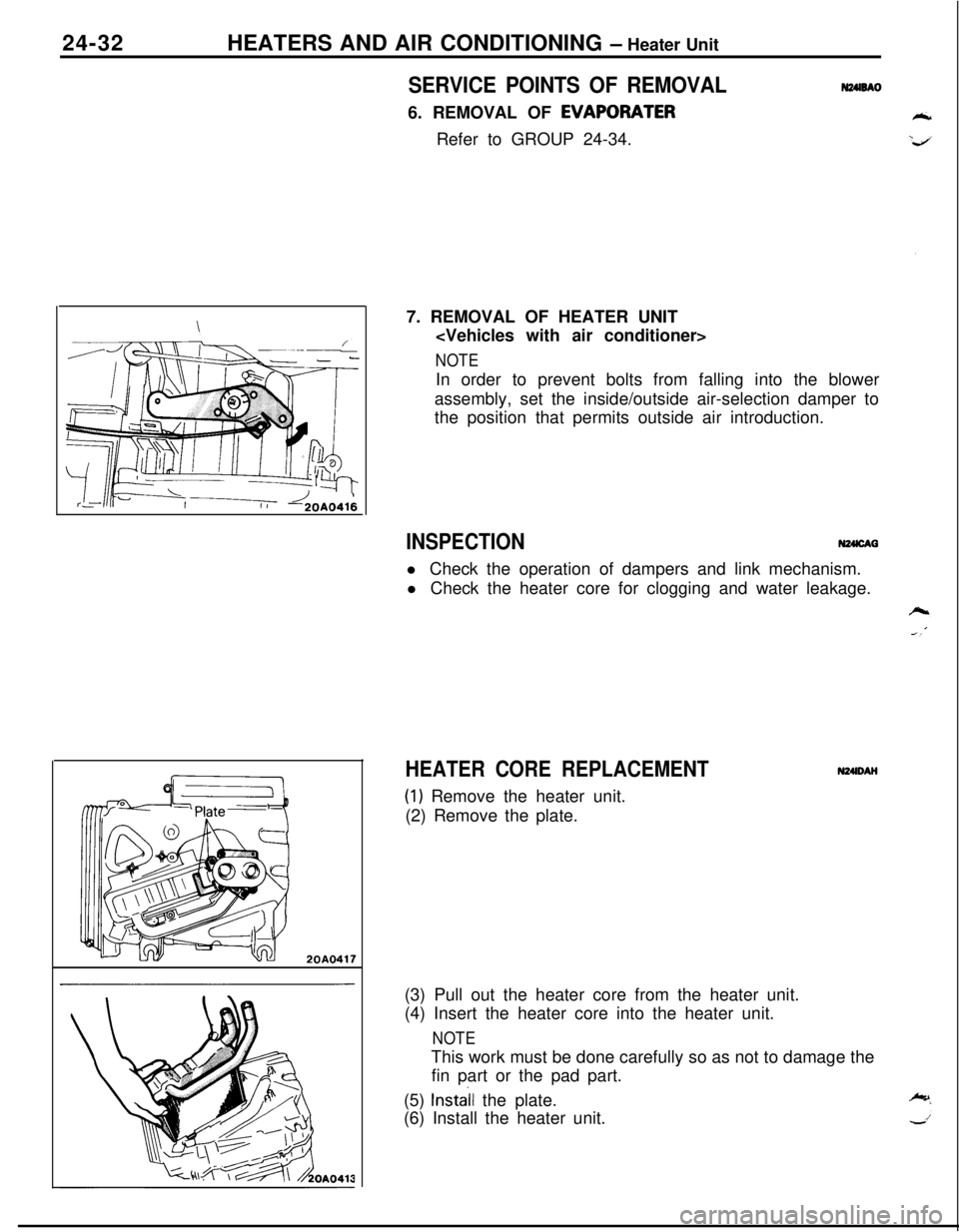
20A04177. REMOVAL OF HEATER UNIT
NOTEIn order to prevent bolts from falling into the blower
assembly, set the inside/outside air-selection damper to
the position that permits outside air introduction.
INSPECTIONN24lcAal Check the operation of dampers and link mechanism.
l Check the heater core for clogging and water leakage.
HEATER CORE REPLACEMENT
(1) Remove the heater unit.
(2) Remove the plate.N24lDAH
(3) Pull out the heater core from the heater unit.
(4) Insert the heater core into the heater unit.
NOTEThis work must be done carefully so as not to damage the
fin part or the pad part.
(5)
Install the plate.
(6) Install the heater unit.
Page 1177 of 1216
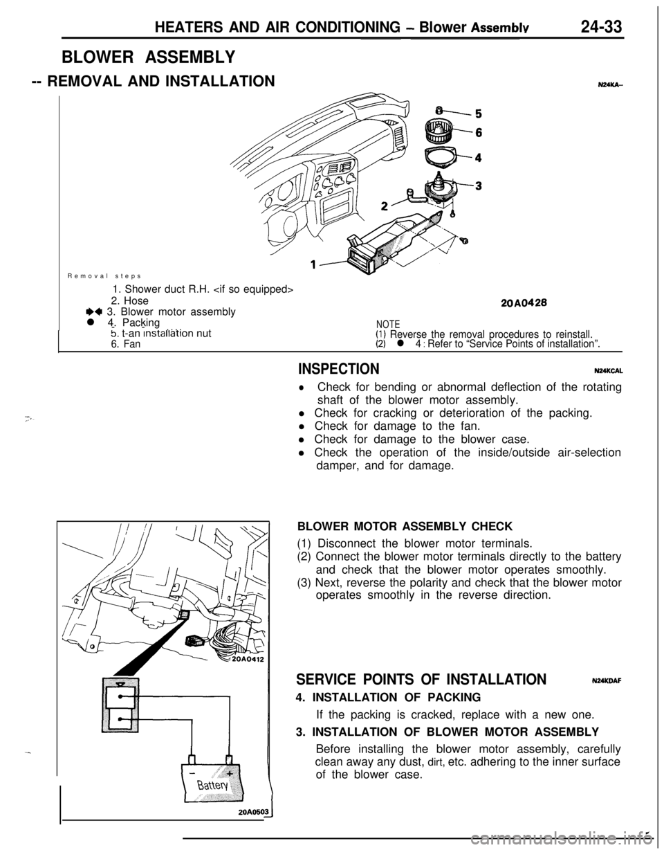
HEATERS AND AIR CONDITIONING - Blower Assemblv24-33Removal steps
1. Shower duct R.H.
2. Hose
+4 3. Blower motor assembly
l 4. Packing
--
. . . .
20A0428
5. t-an lnstallatlon nut6. Fan
NOTE(1) Reverse the removal procedures to reinstall.(2) l 4 : Refer to “Service Points of installation”.
BLOWER ASSEMBLY-- REMOVAL AND INSTALLATIONZOAO50
NUKA-
INSPECTIONN24KCAL
lCheck for bending or abnormal deflection of the rotating
shaft of the blower motor assembly.
l Check for cracking or deterioration of the packing.
l Check for damage to the fan.
l Check for damage to the blower case.
l Check the operation of the inside/outside air-selection
damper, and for damage.
BLOWER MOTOR ASSEMBLY CHECK
(1) Disconnect the blower motor terminals.
(2) Connect the blower motor terminals directly to the battery
and check that the blower motor operates smoothly.
(3) Next, reverse the polarity and check that the blower motor
operates smoothly in the reverse direction.
SERVICE POINTS OF INSTALLATIONNUKDAF4. INSTALLATION OF PACKING
If the packing is cracked, replace with a new one.
3. INSTALLATION OF BLOWER MOTOR ASSEMBLY
Before installing the blower motor assembly, carefully
clean away any dust, dirt, etc. adhering to the inner surface
of the blower case.
Page 1178 of 1216
24-34HEATERS AND AIR CONDITIONING - Evaporator
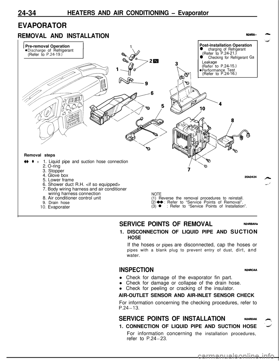
EVAPORATOR
REMOVAL AND INSTALLATION
1 Pre-removal Operation1aDischarge of Refrigerant
(Refer to P.24.19.)Post-installation Operation
l charging of Refrigerant(Refer to P.24-21.)l Checking for Refrigerant Ga:(Refer to
P.24-16.)Removal steps
N l +1. Liquid pipe and suction hose connection2. O-ring
3. Stopper
4. Glove box
5. Lower frame
6. Shower duct R.H.
7. Body wiring harness and air conditioner
wiring harness connection
8. Air conditioner control unit
9. Drain hose
10. Evaporater
2OAO424
NOTE(1) Reverse the removal procedures to reinstall.
(2) ++ : Refer to “Service Points of Removal”.
(3) l : Refer to “Service Points of Installation”.
SERVICE POINTS OF REMOVALN24RBAHa1. DISCONNECTION OF LIQUID PIPE AND SUCTION
HOSEIf the hoses or pipes are disconnected, cap the hoses or
pipes with a blank plug to prevent entry of dust, dirt, and
water.
INSPECTIONN24RCAAl Check for damage of the evaporator fin part.
l Check for damage or collapse of the drain hose.
l Check for peeling or cracking of the insulator.
AIR-OUTLET SENSOR AND AIR-INLET SENSOR CHECK
For information concerning the checking procedures, refer to
P.24-13.
SERVICE POINTS OF INSTALLATIONN24RDAK1. CONNECTION OF LIQUID PIPE AND SUCTION HOSE
For information concerning the installation procedures,
refer to
P.24-23.
Page 1179 of 1216
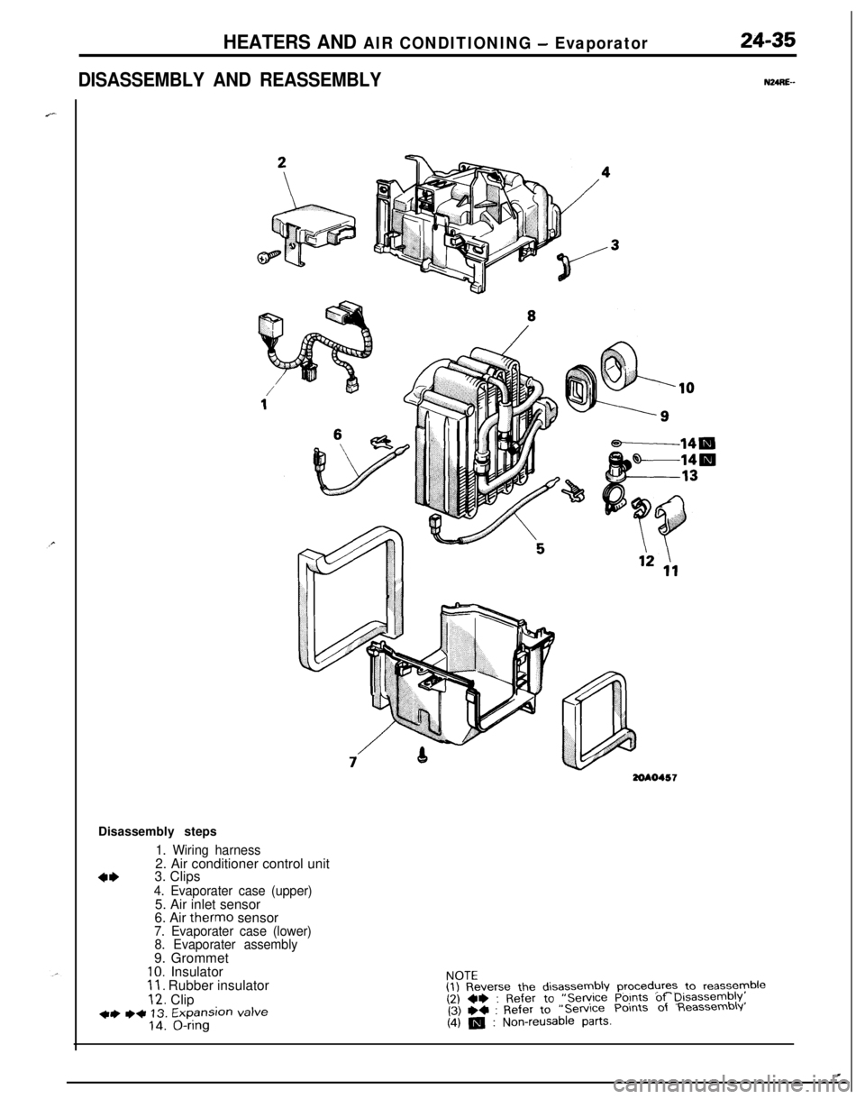
HEATERS AND AIR CONDITIONING - Evaporator
DISASSEMBLY AND REASSEMBLY
24-35
NURE--
3ZOAO457Disassembly steps
1. Wiring harness2. Air conditioner control unit
4*3. Clips4. Evaporater case (upper)5. Air inlet sensor
6. Air therm0 sensor
7. Evaporater case (lower)
8. Evaporater assembly9. Grommet
IO. Insulator11. Rubber insulator
12. Clip+) ++ 13. Expansion valve14. O-ringNOTE
(1) Reverse the disassembly procedures to reassyyble(2) ~~ : Refer to “Service Points of Disassembly,(3) +4 : Refer to“Service Points of Reassembly
(4) m : Non-reusable parts.
.
Page 1180 of 1216
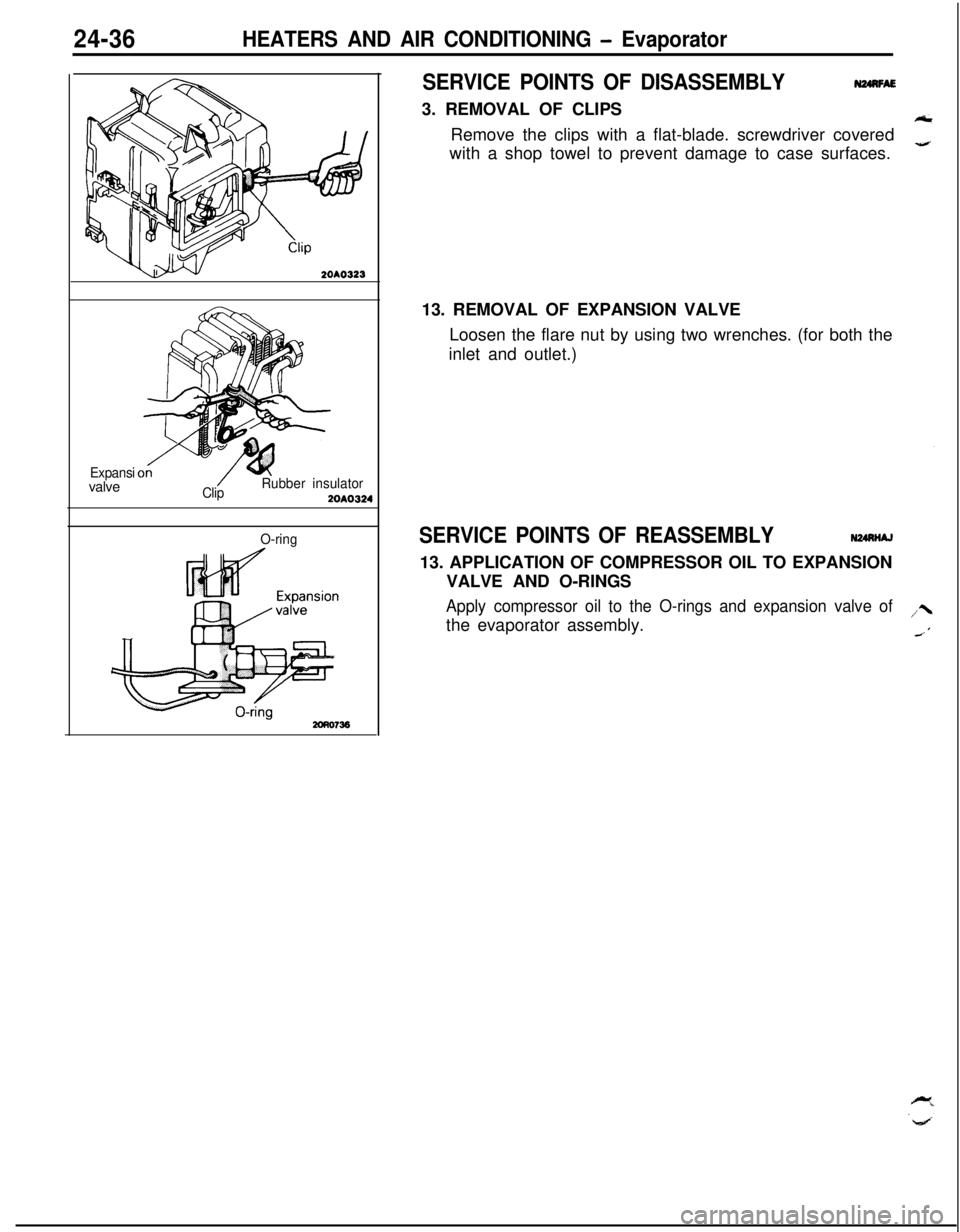
24-36HEATERS AND AIR CONDITIONING - Evaporator
SERVICE POINTS OF DISASSEMBLY3. REMOVAL OF CLIPS
N24nFAERemove the clips with a flat-blade. screwdriver covered
with a shop towel to prevent damage to case surfaces.
2OAO323
Expansivalve
ClipRubber insulator2OAO324
O-ring13. REMOVAL OF EXPANSION VALVE
Loosen the flare nut by using two wrenches. (for both the
inlet and outlet.)SERVICE POINTS OF REASSEMBLYN24nNAJ13. APPLICATION OF COMPRESSOR OIL TO EXPANSION
VALVE AND O-RINGS
Apply compressor oil to the O-rings and expansion valve ofthe evaporator assembly.