heater MITSUBISHI ECLIPSE 1991 Owner's Guide
[x] Cancel search | Manufacturer: MITSUBISHI, Model Year: 1991, Model line: ECLIPSE, Model: MITSUBISHI ECLIPSE 1991Pages: 1216, PDF Size: 67.42 MB
Page 1161 of 1216
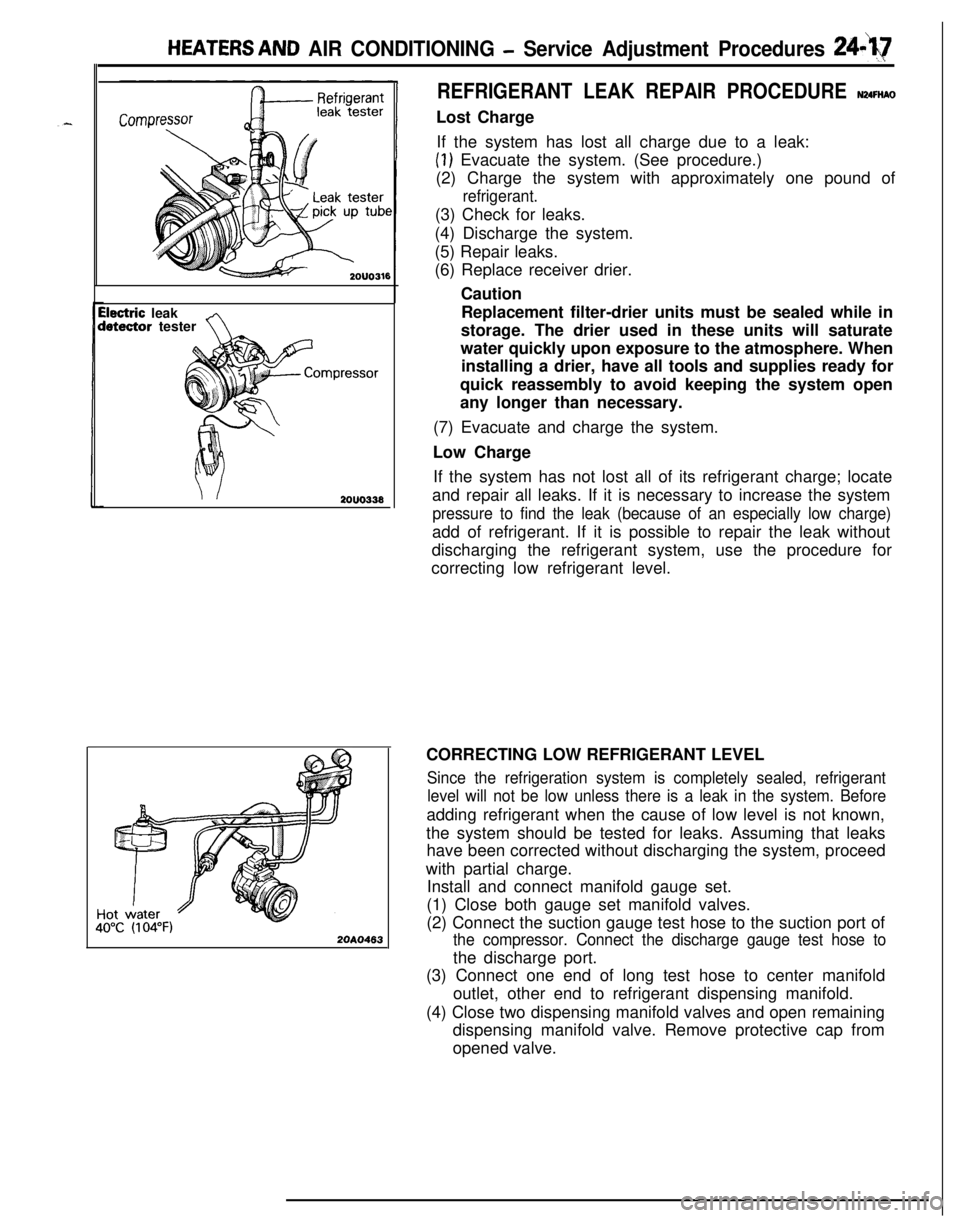
HEATERS AND AIR CONDITIONING - Service Adjustment Procedures 24-Q
ilectric leakletector tester
2OUO333
40°C(I 04°F)20A0463
REFRIGERANT LEAK REPAIR PROCEDURE N24FtiAOLost Charge
If the system has lost all charge due to a leak:
(1) Evacuate the system. (See procedure.)
(2) Charge the system with approximately one pound of
refrigerant.(3) Check for leaks.
(4) Discharge the system.
(5) Repair leaks.
(6) Replace receiver drier.
Caution
Replacement filter-drier units must be sealed while in
storage. The drier used in these units will saturate
water quickly upon exposure to the atmosphere. When
installing a drier, have all tools and supplies ready for
quick reassembly to avoid keeping the system open
any longer than necessary.
(7) Evacuate and charge the system.
Low Charge
If the system has not lost all of its refrigerant charge; locate
and repair all leaks. If it is necessary to increase the system
pressure to find the leak (because of an especially low charge)add of refrigerant. If it is possible to repair the leak without
discharging the refrigerant system, use the procedure for
correcting low refrigerant level.
CORRECTING LOW REFRIGERANT LEVEL
Since the refrigeration system is completely sealed, refrigerant
level will not be low unless there is a leak in the system. Beforeadding refrigerant when the cause of low level is not known,
the system should be tested for leaks. Assuming that leaks
have been corrected without discharging the system, proceed
with partial charge.
Install and connect manifold gauge set.
(1) Close both gauge set manifold valves.
(2) Connect the suction gauge test hose to the suction port of
the compressor. Connect the discharge gauge test hose tothe discharge port.
(3) Connect one end of long test hose to center manifold
outlet, other end to refrigerant dispensing manifold.
(4) Close two dispensing manifold valves and open remaining
dispensing manifold valve. Remove protective cap from
opened valve.
Page 1162 of 1216
24-18 HEATERS AND AIR CONDITIONING - Service Adjustment Procedures
(5) Screw a can of R-12 to the opened manifold valve. Be sure
gasket is in place and in good condition. Tighten refrigerantcan and manifold locking nut to insure a good seal. Do not
overtighten 8 to
11 Nm (6 to 8 ft.lbs.) is sufficient if gasket
is in good condition.
(6) Turn manifold valve (above the refrigerant can) completely
clockwise to puncture the can. This closes the valve and
seals the refrigerant in the can.
Caution
Never heat small cans of refrigerant over
40°C (104°F)as they may explode.
(7) Place the refrigerant in a large pan of water heated to 52°C
(104°F). Place pan of water containing the refrigerant can
on an accurate scale so the amount of refrigerant added
can be weighed. Open the refrigerant manifold valve.
(8) Purge all air from test hoses. Air in the system will be
trapped in the condenser causing abnormally high dis-
charge pressures and interfering with condensing of the
refrigerant.(9) Slightly loosen both test hoses at the gauge set manifold.
Tighten the hoses as soon as the air is purged.
(10)Slightly loosen charging hose connection at gauge set
manifold. This will purge air from the charging hose.
Tighten connection as soon as air is purged.
(I l)With vehicle windows open and hood up, operate engine at1,500 rpm and jump the low pressure switch terminals
located on the receiver drier so the clutch will remain
engaged.
(12)Place air conditioner control on air conditioner and place theblower switch on high.
(13)lf necessary, block the condenser to maintain a discharge
pressure of 1,422 to 1,520
kPa (206 to 220 psi). System
must be charged through the evaporator suction service
ports as follows:
(a) Slowly open the suction service gauge valve.
Meter flow of refrigerant by adjusting, the suciton
service gauge valve so that pressure registered at the
suction service gauge does not exceed 345 kPa (50 psi).Keep refrigerant container upright.
(b) Add refrigerant gas until there is no foam visible at the
sight glass.
Add an additional
170 g (6 oz.)
(c) Close the suction gauge valve.
CautionToo much refrigerant in the system can cause
abnormally high discharge pressures. Care must beused so that the exact recommended amount or
refrigerant is added after foam clears in the sight
glass.(d) Close dispensing manifold valve. Remove test hoses
and adapters from the service ports of compressor,
install protective caps at service ports and reconnect
wiring.(e) Check system performance.
(P.24- 16.)
e
. i”
A
i-4
Page 1163 of 1216
-.
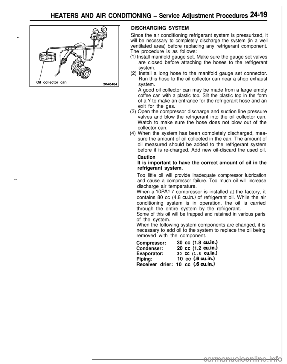
HEATERS AND AIR CONDITIONING - Service Adjustment Procedures 241$19Oil collector can
2OAO464DISCHARGING SYSTEM
Since the air conditioning refrigerant system is pressurized, it
will be necessary to completely discharge the system (in a wellventilated area) before replacing any refrigerant component.
The procedure is as follows:
(1) Install manifold gauge set. Make sure the gauge set valves
are closed before attaching the hoses to the refrigerant
system.(2) Install a long hose to the manifold gauge set connector.
Run this hose to the oil collector can near a shop exhaust
system.A good oil collector can may be made from a large empty
coffee can with a plastic top. Slit the plastic top in the formof a
Y to make an entrance for the refrigerant hose and an
exit for the gas.
(3) Open the compressor discharge and suction line pressure
valves and blow the refrigerant into the oil collector can.
Watch to make sure the hose does not blow out of the
collector can.
(4) When the system has been completely discharged, mea-
sure the amount of oil collected in the can. The amount of
oil measured should be added to the refrigerant system
before it is re-charged. Add new oil-discard the used oil.
CautionIt is important to have the correct amount of oil in the
refrigerant system.
Too little oil will provide inadequate compressor lubrication
and cause a compressor failure. Too much oil will increasedischarge air temperature.
When a IOPAI 7 compressor is installed at the factory, it
contains 80 cc (4.8
cu.in.) of refrigerant oil. While the air
conditioning system is in operation, the oil is carried
through the entire system by the refrigerant.
Some of this oil will be trapped and retained in various partsof the system.
When the following system components are changed, it is
necessary to add oil to the system to replace the oil being
removed with the component.
Compressor:30 cc (1.8 cu.in.1
Condenser:20 cc (1.2 cu.in.1
Evaporator:30 cc (1.8 cu.in.)
Piping:10 cc (.6 cu.in.1Receiver drier: 10 cc
(.6 cu.in.1
Page 1164 of 1216
24-20 HEATERS AND AIR CONDITIONING - Service Adjustment Procedures
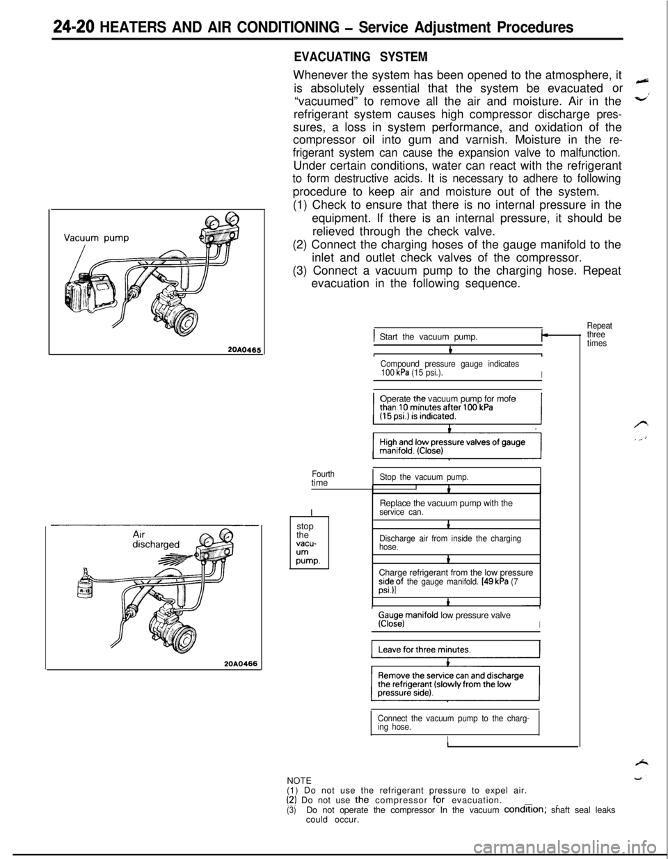
20A0465
20A0466
EVACUATING SYSTEMWhenever the system has been opened to the atmosphere, it
is absolutely essential that the system be evacuatedor
“vacuumed” to remove all the air and moisture. Air in the
refrigerant system causes high compressor discharge
pres-sures, a loss in system performance, and oxidation of the
compressor oil into gum and varnish. Moisture in the
re-
frigerant system can cause the expansion valve to malfunction.Under certain conditions, water can react with the refrigerant
to form destructive acids. It is necessary to adhere to followingprocedure to keep air and moisture out of the system.
(1) Check to ensure that there is no internal pressure in the
equipment. If there is an internal pressure, it should be
relieved through the check valve.
(2) Connect the charging hoses of the gauge manifold to the
inlet and outlet check valves of the compressor.
(3) Connect a vacuum pump to the charging hose. Repeat
evacuation in the following sequence.
Repeat
) Start the vacuum pump.I-
bIICompound pressure gauge indicates
100 kPa (15 psi.).IOperate the vacuum pump for mofe
Fourthtime
IStop the vacuum pump.IbReplace the vacuum pump with the
service can.stop
the
vacu-
;Ummp.
1
Discharge air from inside the charging
hose.
bCharge refrigerant from the low pressure
;s”;pf the gauge manifold. [49 kPa (7
Ga;iejmanifold low pressure valveI
Connect the vacuum pump to the charg-
ing hose.
INOTE
(1) Do not use the refrigerant pressure to expel air.
(‘2) Do not use the. compressor for evacuation.___(3)Do not operate the compressor In the vacuum condrtlon; shaft seal leaks
could occur.
three
times
Page 1165 of 1216
i
HEATERS AND AIR CONDITIONING - Service Adjustment Procedures 24-21Hot water40°C (104°F)
1467CHARGING SYSTEM
The refrigerant system must have been evacuated using the
previous procedure before charging.
Charge using only R-l 2 refrigerant.
R-12 is available in bulk
tanks or small cans. Follow the safety precautions for handling
R-12 as listed in this group.
Charging with Small Cans
When using disposable cans of this type, follow carefully the
can manufacturers instructions.
Caution
Never use these cans to charge into the high pressure side
of the system (compressor discharge port) or into a systemthat is at high temperature, because the high system
pressures could be transferred into the charging can
causing it to explode.
Keep the refrigerant manifold valves capped when not in use.
Keep a supply of extra refrigerant-can-to-refrigerant-manifold
gaskets on hand so that gaskets can be replaced periodically.
This will insure a good seal without excessive tightening of thecan or the manifold nuts.
(1) Attach center hose from manifold gauge set to refrigerant
dispensing manifold. Turn refrigerant manifold valves com-pletely anticlockwise so they are fully open.
Remove protective caps from refrigerant manifold.
(2) Screw refrigerant cans into manifold. Be sure
manifold-to-can gasket is in place and in good condition. Tighten can
and manifold nuts to 8 to 11 Nm (6 to 8
ft.lbs.).(3) Turn refrigerant manifold valves completely clockwise to
puncture the cans and close the manifold valves.
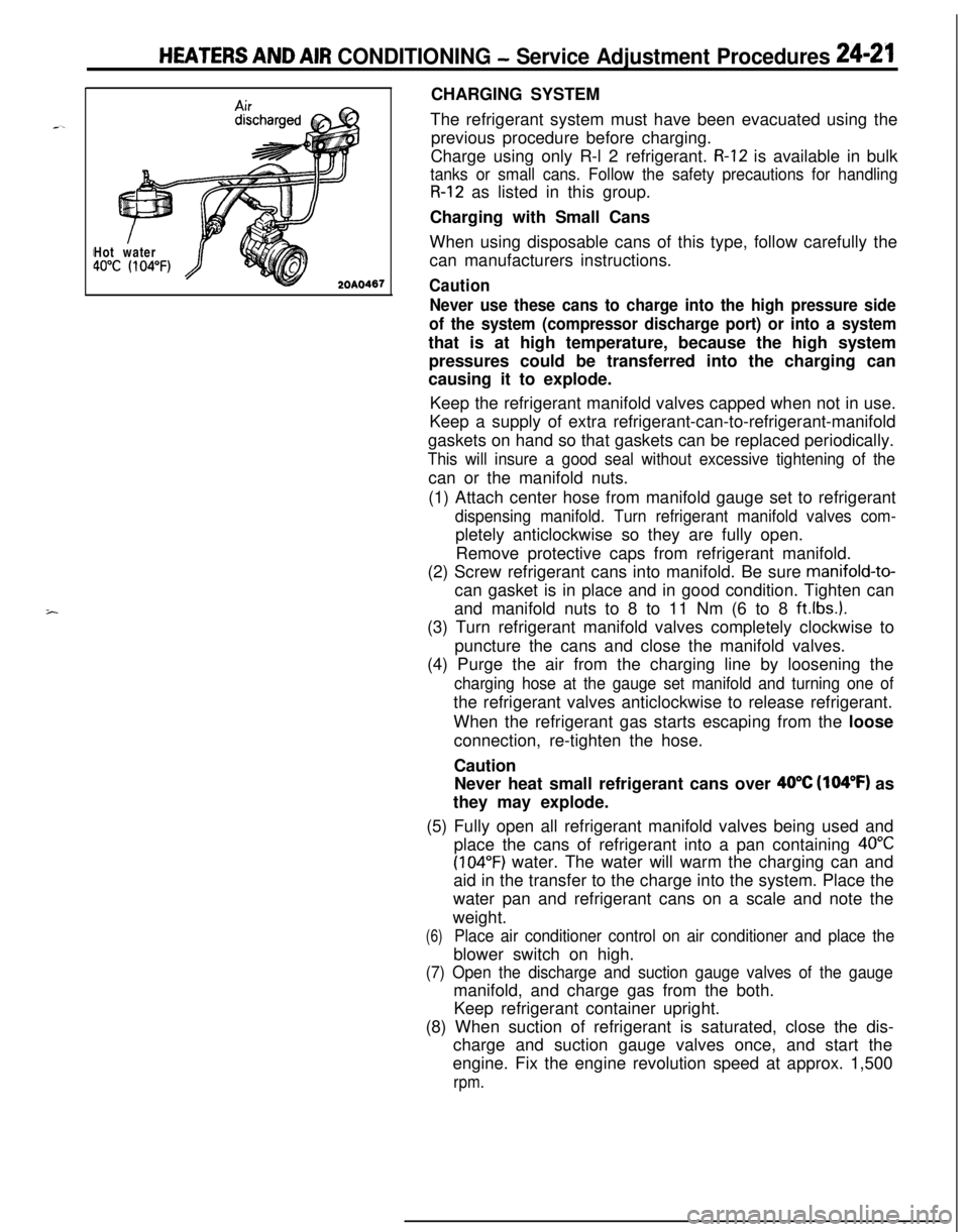
(4) Purge the air from the charging line by loosening the
charging hose at the gauge set manifold and turning one ofthe refrigerant valves anticlockwise to release refrigerant.
When the refrigerant gas starts escaping from the loose
connection, re-tighten the hose.
Caution
Never heat small refrigerant cans over
40°C (104°F) as
they may explode.
(5) Fully open all refrigerant manifold valves being used and
place the cans of refrigerant into a pan containing
40°C
(104°F) water. The water will warm the charging can and
aid in the transfer to the charge into the system. Place the
water pan and refrigerant cans on a scale and note the
weight.
(6)Place air conditioner control on air conditioner and place theblower switch on high.
(7) Open the discharge and suction gauge valves of the gaugemanifold, and charge gas from the both.
Keep refrigerant container upright.
(8) When suction of refrigerant is saturated, close the dis-
charge and suction gauge valves once, and start the
engine. Fix the engine revolution speed at approx. 1,500
rpm.
Page 1166 of 1216
24-22 HEATERS AND AIR CONDITIONING - Service Adjustment Procedures(9) Charge through the suction side of the system by slowly
opening the suction manifold valve. Adjust the valve as
necessary so charging pressure does not exceed 345
kPa 6(50 psi). Maintain the temperature of the water in the pan w’
by adding warm water as necessary.
Note the weight of water added, to ensure accuracy when
determining amount of refrigerant added to system.
(lO)When specified refrigerant charge Max. 925
g (32 oz.) has
entered the system, close the gauge set manifold valves,
refrigerant manifold valves, and
reconnnect wiring. Each
can contains 397
g (14 oz.) of R-l 2. Use 2 l/2 cans.
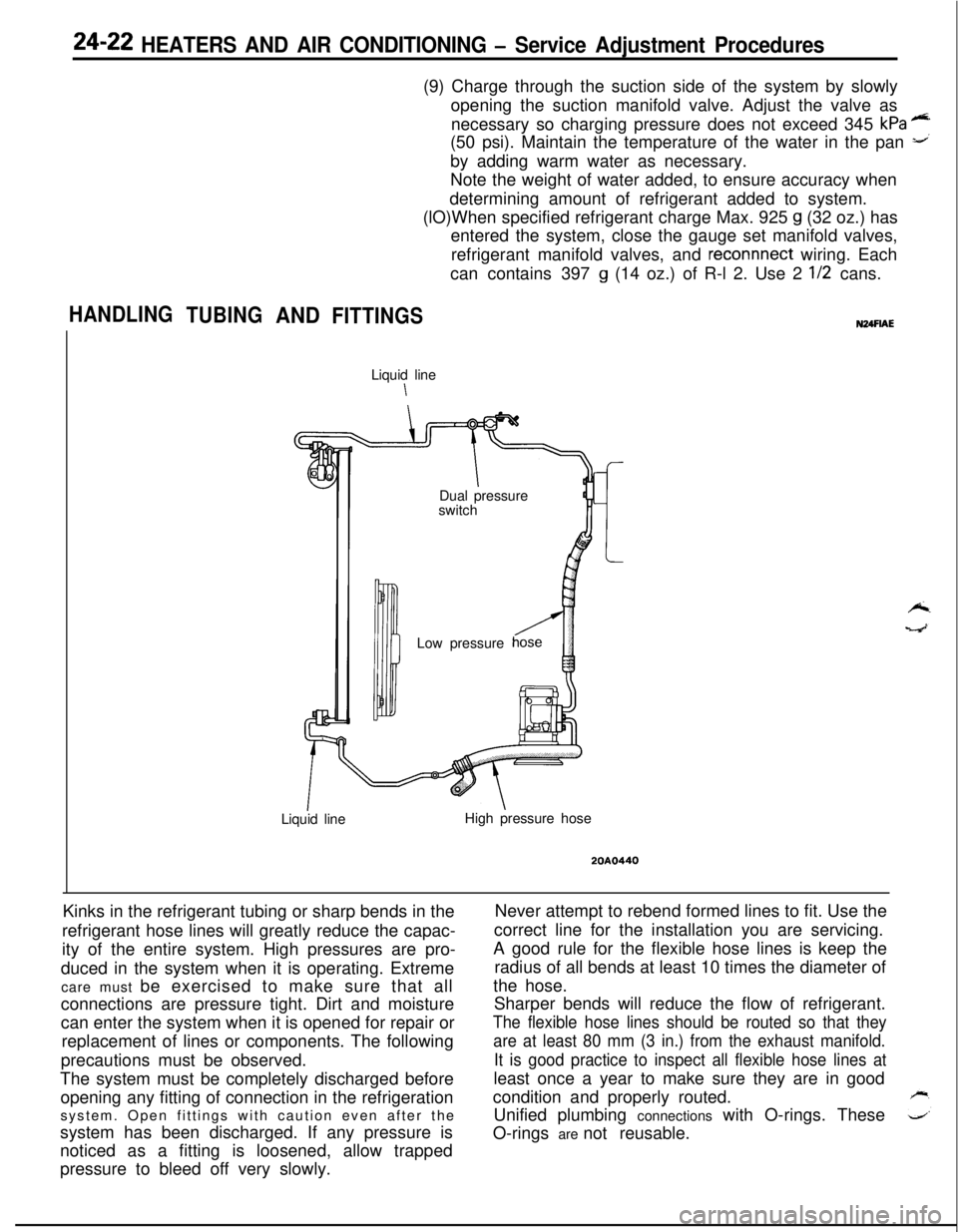
HANDLING
TUBINGANDFITTINGSLiquid line
\
IDual pressure
switch
Low pressure
Liquid lineHigh pressure hose
20A0440Kinks in the refrigerant tubing or sharp bends in the
refrigerant hose lines will greatly reduce the capac-
ity of the entire system. High pressures are pro-
duced in the system when it is operating. Extreme
care must be exercised to make sure that all
connections are pressure tight. Dirt and moisture
can enter the system when it is opened for repair or
replacement of lines or components. The following
precautions must be observed.
The system must be completely discharged before
opening any fitting of connection in the refrigeration
system. Open fittings with caution even after the
system has been discharged. If any pressure is
noticed as a fitting is loosened, allow trapped
pressure to bleed off very slowly.Never attempt to rebend formed lines to fit. Use the
correct line for the installation you are servicing.
A good rule for the flexible hose lines is keep the
radius of all bends at least 10 times the diameter of
the hose.
Sharper bends will reduce the flow of refrigerant.
The flexible hose lines should be routed so that they
are at least 80 mm (3 in.) from the exhaust manifold.
It is good practice to inspect all flexible hose lines atleast once a year to make sure they are in good
condition and properly routed.
Unified plumbing connections with O-rings. These
O-rings are not reusable.
Page 1167 of 1216
HEATERS AND AIR CONDITIONING - Service Adiustment Procedures 24-23
<
we2ouo2er
< 1.8L Engine>Tension/ wllevO-RING INSTALLATION
(1) Clean sealing surface.
(2) Make sure O-ring does not have any scratches.
(3) Connect fitting, install fastener, and torque to amount
shown in the illustration.
The internal parts of the refrigeration system will remain in
a state of chemical stability as long as pure-moisture-free
R-12 and refrigerant oil is used. Abnormal amounts of dirt,
moisture of air can upset the chemical stability and cause
operational troubles or even serious damage if present in
more than minute quantities.
When it is necessary to open the refrigeration system, have
everything you will need to service the system ready so the
system will not be left open any longer than necessary. Capor plug all lines and fittings as soon as they are opened to
prevent the entrance of dirt and moisture. All lines and
components in parts stock should be capped or sealed until
they are ready to be used. All tools, including the refrigerant
dispensing manifold, the gauge set manifold and test hosesshould be kept clean and dry.
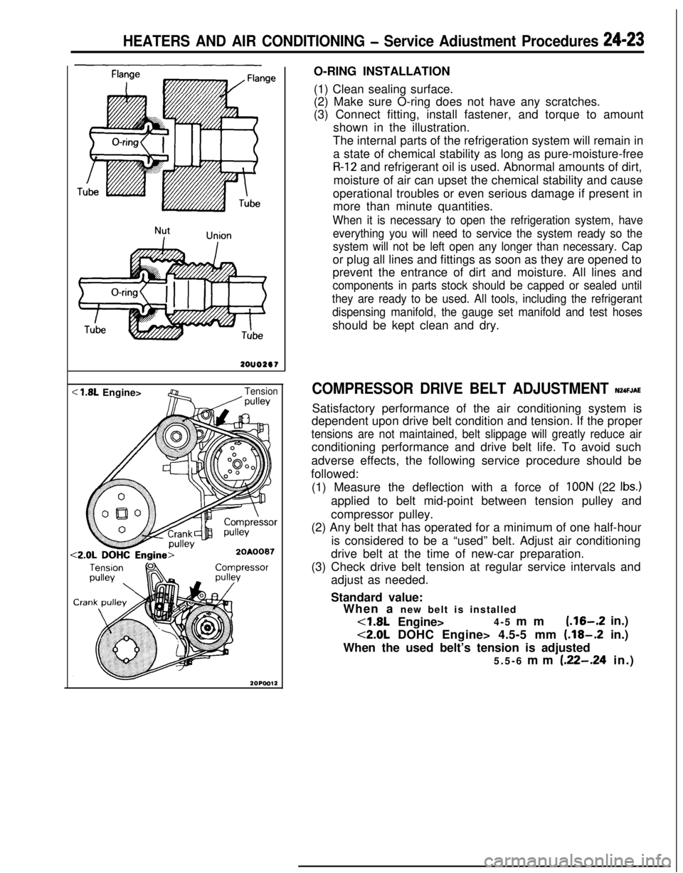
COMPRESSOR DRIVE BELT ADJUSTMENT N24FJAESatisfactory performance of the air conditioning system is
dependent upon drive belt condition and tension. If the proper
tensions are not maintained, belt slippage will greatly reduce airconditioning performance and drive belt life. To avoid such
adverse effects, the following service procedure should be
followed:
(1) Measure the deflection with a force of
IOON (22 Ibs.)applied to belt mid-point between tension pulley and
compressor pulley.
(2) Any belt that has operated for a minimum of one half-hour
is considered to be a “used” belt. Adjust air conditioning
drive belt at the time of new-car preparation.
(3) Check drive belt tension at regular service intervals and
adjust as needed.
Standard value:
When a new belt is installed<1.8L Engine>4-5 mm
(.16-.2 in.)
<2.0L DOHC Engine> 4.5-5 mm (.18-.2 in.)
When the used belt’s tension is adjusted
5.5-6 mm
(.22-.24 in.)
Page 1168 of 1216
24-24 HEATERS AND AIR CONDITIONING - Service Adjustment Procedures
COMPRESSOR NOISENUFIABWhen investigating an air conditioning related noise, you must
first know the conditions when the noise occurs. These
conditions are: weather, vehicle speed, in gear or neutral,
engine temperature or any other special conditions.
Noises that develop during air conditioning operation can oftenbe misleading. For example: what sounds like a failed front
bearing or connecting rod, may be caused by loose bolts, nuts,mounting brackets, or a loose clutch assembly. Verify acces-
sory drive belt tension (power steering, or alternator).
Improper accessory drive belt tension can cause a misleading
noise when the compressor is engaged and little or no noise
when the compressor is disengaged.
Drive belts are speed sensitive. That is, at different engine
speeds, and depending upon belt tension, belts can develop
unusual noises that are often mistaken for mechanical prob-
lems within the compressor.
Adjustment Procedures
(1) Select a quiet area for testing. Duplicate conditions as
much as possible. Switch compressor on and off several
times to clearly identify compressor noise.
To duplicate high ambient conditions (high head pressure),restrict air flow through condenser. Install manifold gauge
set to make sure discharge pressure doesn’t exceed 2,070
kPa (300 psi).
(2) Tighten all compressor mounting bolts, clutch mounting
bolt, and compressor drive belt. Check to assure clutch coilis tight (no rotation or wobble).
(3) Check refrigerant hoses for rubbing or interference that cancause unusual noises.
(4) Check refrigerant charge (See “Charging the System”).
(5) Recheck compressor noise as in Step 1.
(6) If noise still exists, loosen compressor mounting bolts and
retorque. Repeat Step 1.
(7) If noise continues, replace compressor and repeat Step 1.
Condenser fan motor relay,
Magnet clutch
relay, Blower
motor High
relayHeater relayML0312
16W908
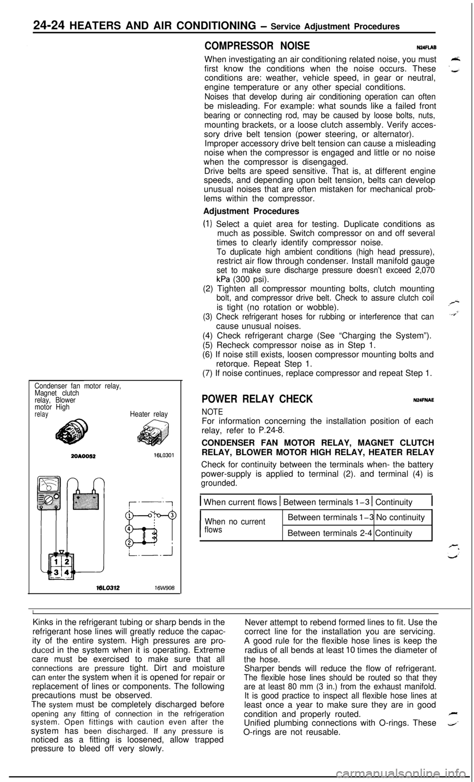
POWER RELAY CHECKNUFNAE
NOTEFor information concerning the installation position of each
relay, refer to
P.24-8.CONDENSER FAN MOTOR RELAY, MAGNET CLUTCH
RELAY, BLOWER MOTOR HIGH RELAY, HEATER RELAY
Check for continuity between the terminals when- the battery
power-supply is applied to terminal (2). and terminal (4) is
grounded.
1 When current flows 1 Between terminals l-3 1 Continuity1
I
When no currentBetween terminals l-3 No continuity
flowsBetween terminals 2-4 Continuity
IKinks in the refrigerant tubing or sharp bends in the
Never attempt to rebend formed lines to fit. Use the
refrigerant hose lines will greatly reduce the
capac-correct line for the installation you are servicing.
ity of the entire system. High pressures are
pro-A good rule for the flexible hose lines is keep the
duced in the system when it is operating. Extreme
radius of all bends at least 10 times the diameter of
care must be exercised to make sure that all
the hose.
connections are pressure tight. Dirt and moisture
Sharper bends will reduce the flow of refrigerant.
can enter the system when it is opened for repair or
The flexible hose lines should be routed so that theyreplacement of lines or components. The following
are at least 80 mm (3 in.) from the exhaust manifold.precautions must be observed.
It is good practice to inspect all flexible hose lines atThe system must be completely discharged before
least once a year to make sure they are in good
opening any fitting of connection in the refrigeration
condition and properly routed.
Fsystem. Open fittings with caution even after the
Unified plumbing connections with O-rings. These
4’system has been discharged. If any pressure is
noticed as a fitting is loosened, allow trappedO-rings are not reusable.
pressure to bleed off very slowly.
Page 1169 of 1216
HEATERS AND AIR CONDITIONING - Service Adjustment Procedures 24-25
16A1077
20AO499
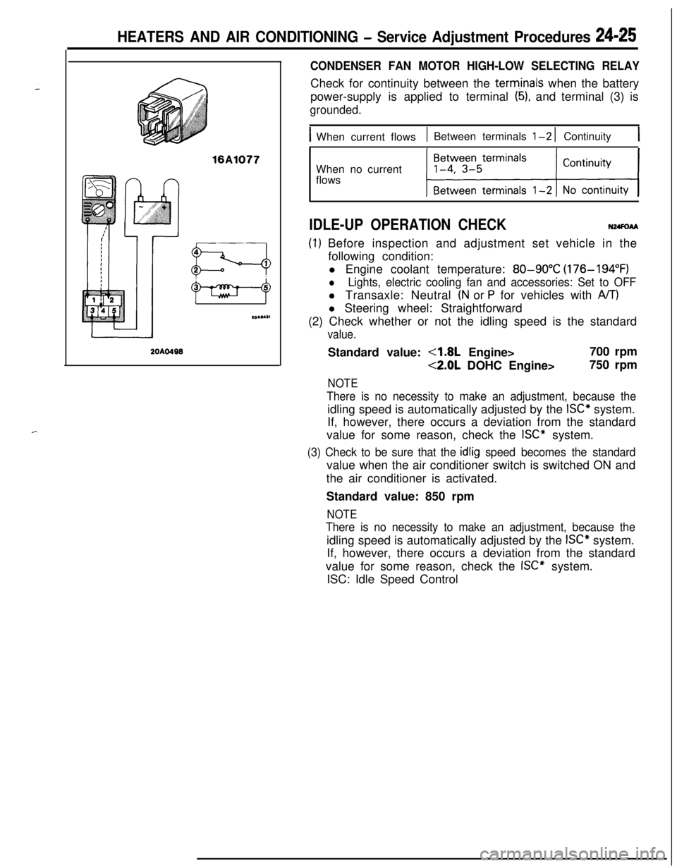
CONDENSER FAN MOTOR HIGH-LOW SELECTING RELAYCheck for continuity between the
term,inals when the battery
power-supply is applied to terminal
(5), and terminal (3) is
grounded.
IWhen current flows1 Between terminals l-2 1 Continuity1When no current
flows
IDLE-UP OPERATION CHECKN24FoAA
(I) Before inspection and adjustment set vehicle in the
following condition:
l Engine coolant temperature:
80-90°C (176-194°F)
lLights, electric cooling fan and accessories: Set to OFFl Transaxle: Neutral
(N or P for vehicles with A/T)l Steering wheel: Straightforward
(2) Check whether or not the idling speed is the standard
value.Standard value:
4.8L Engine>700 rpm
<2.0L DOHC Engine>750 rpm
NOTE
There is no necessity to make an adjustment, because theidling speed is automatically adjusted by the
ISC” system.
If, however, there occurs a deviation from the standard
value for some reason, check the
ISC” system.
(3) Check to be sure that the idlig speed becomes the standardvalue when the air conditioner switch is switched ON and
the air conditioner is activated.
Standard value: 850 rpm
NOTE
There is no necessity to make an adjustment, because theidling speed is automatically adjusted by the
ISC” system.
If, however, there occurs a deviation from the standard
value for some reason, check the
ISC” system.
ISC: Idle Speed Control
Page 1170 of 1216
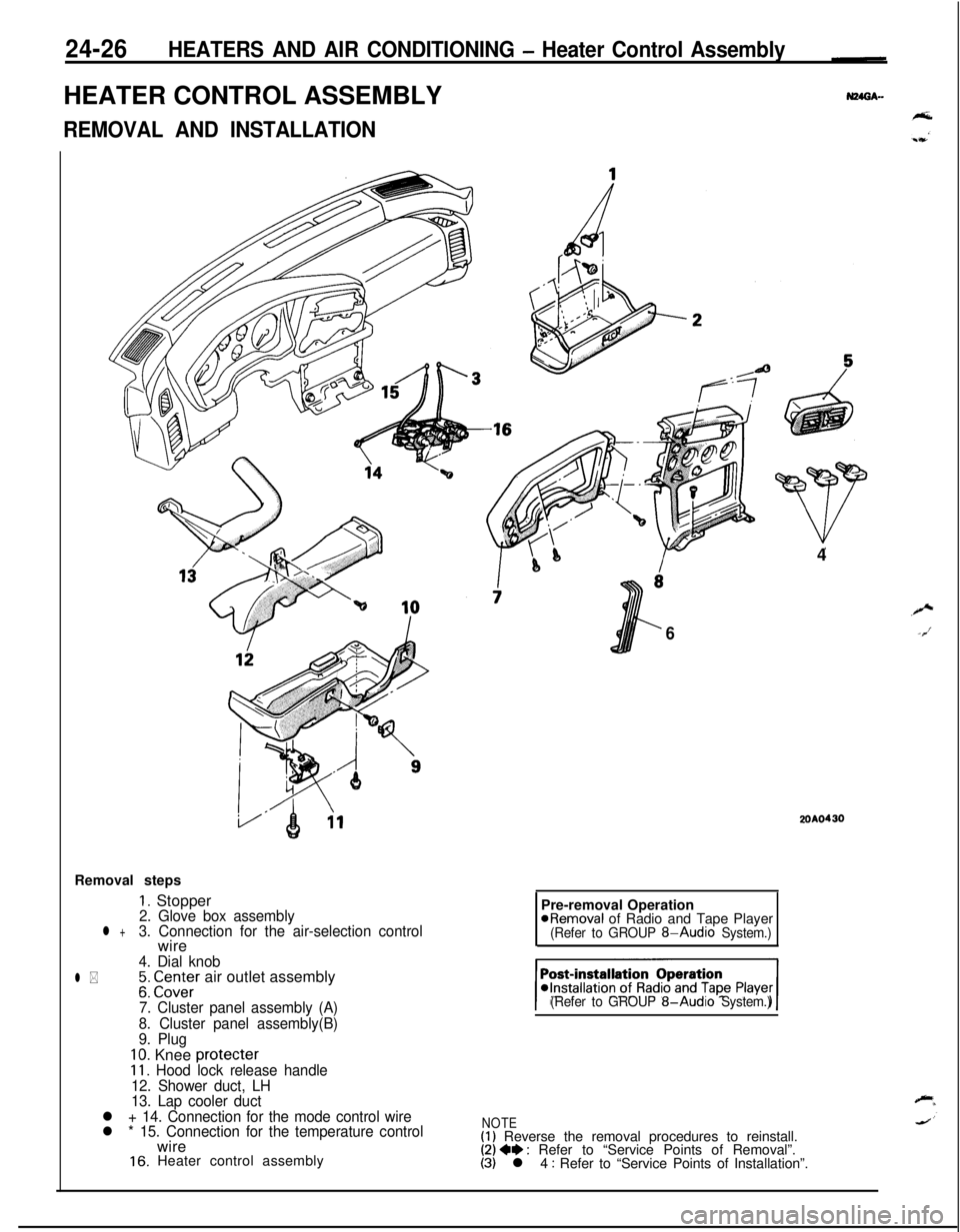
24-26HEATERS AND AIR CONDITIONING - Heater Control AssemblyHEATER CONTROL ASSEMBLY
REMOVAL AND INSTALLATIONRemoval steps
1. Stopper2. Glove box assemblyl +3. Connection for the air-selection controlwire
4. Dial knob
l *;: CI.Z;Er air outlet assembly
7. Cluster panel assembly (A)
8. Cluster panel assembly(B)
9. Plug
10. Knee protecter11. Hood lock release handle
12. Shower duct, LH
13. Lap cooler duct
l + 14. Connection for the mode control wire
l * 15. Connection for the temperature controlwire
16. Heater control assembly4
6
2OAO430Pre-removal Operation
@Removal of Radio and Tape Player(Refer to GROUP 8-Audio System.)
(Refer to GROUP
8-Audio System.)
NOTE(1) Reverse the removal procedures to reinstall.(2) 4e : Refer to “Service Points of Removal”.(3) l 4 : Refer to “Service Points of Installation”.