MITSUBISHI ECLIPSE 1991 Service Manual
ECLIPSE 1991
MITSUBISHI
MITSUBISHI
https://www.carmanualsonline.info/img/19/57104/w960_57104-0.png
MITSUBISHI ECLIPSE 1991 Service Manual
Trending: ESP, torque, torque specification, wheel, check engine light, low beam, spark plugs replace
Page 821 of 1216
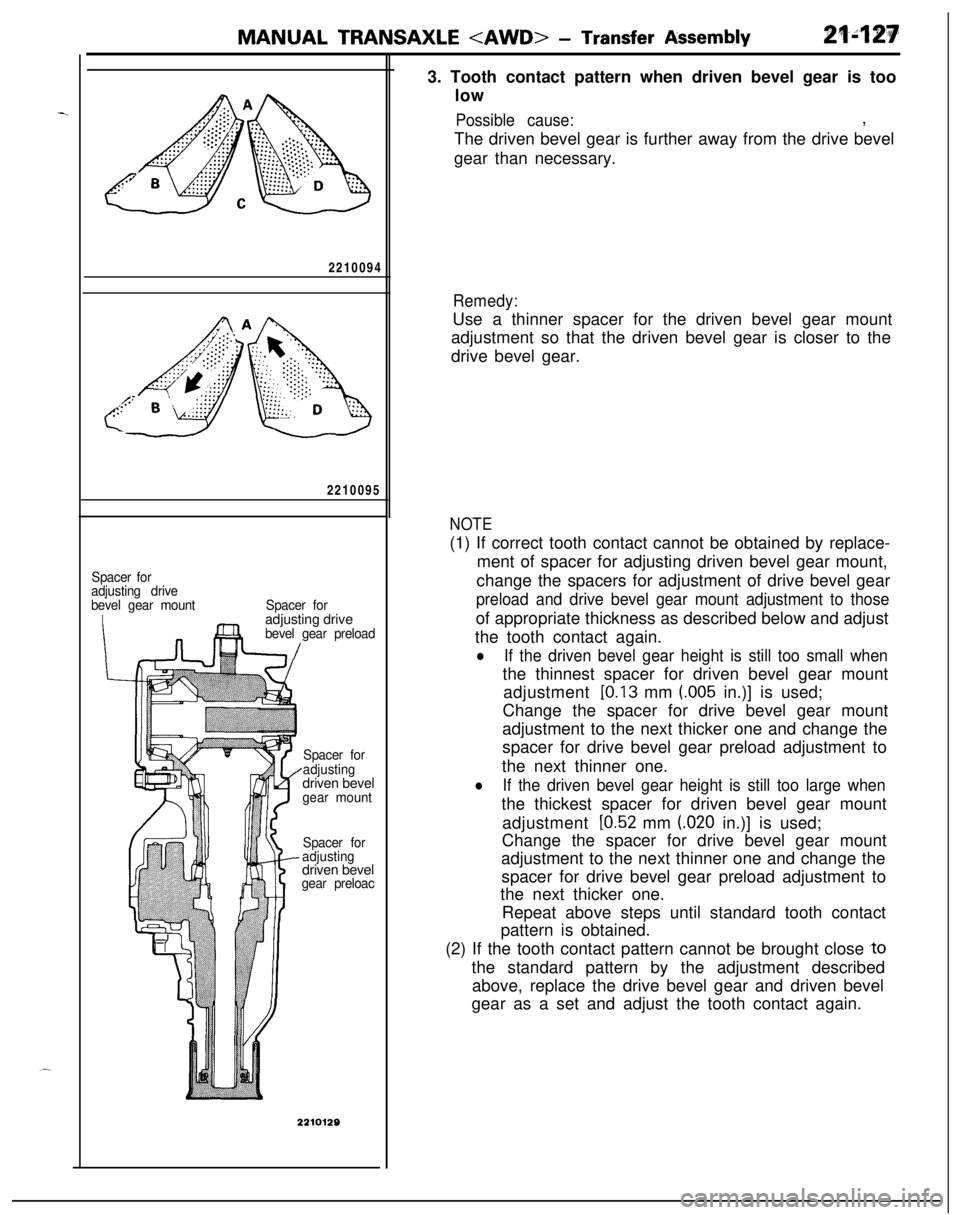
MANUAL TRANSAXLE - Transfer Assembly2210094
2210095
Spacer for
adjusting drive
bevel gear mount
ISpacer foradjusting drive
bevel gear preload
Spacer for
adjustingdriven bevel
gear mount
Spacer for
adjustingdriven bevel
gear preloac3. Tooth contact pattern when driven bevel gear is too
low
Possible cause:,
The driven bevel gear is further away from the drive bevel
gear than necessary.
Remedy:Use a thinner spacer for the driven bevel gear mount
adjustment so that the driven bevel gear is closer to the
drive bevel gear.
NOTE(1) If correct tooth contact cannot be obtained by replace-
ment of spacer for adjusting driven bevel gear mount,
change the spacers for adjustment of drive bevel gear
preload and drive bevel gear mount adjustment to thoseof appropriate thickness as described below and adjust
the tooth contact again.
lIf the driven bevel gear height is still too small whenthe thinnest spacer for driven bevel gear mount
adjustment
[0.13 mm (.005 in.)] is used;
Change the spacer for drive bevel gear mount
adjustment to the next thicker one and change the
spacer for drive bevel gear preload adjustment to
the next thinner one.
lIf the driven bevel gear height is still too large whenthe thickest spacer for driven bevel gear mount
adjustment
[0.52 mm (020 in.)] is used;
Change the spacer for drive bevel gear mount
adjustment to the next thinner one and change the
spacer for drive bevel gear preload adjustment to
the next thicker one.
Repeat above steps until standard tooth contact
pattern is obtained.
(2) If the tooth contact pattern cannot be brought close
,tothe standard pattern by the adjustment described
above, replace the drive bevel gear and driven bevel
gear as a set and adjust the tooth contact again.
Page 822 of 1216
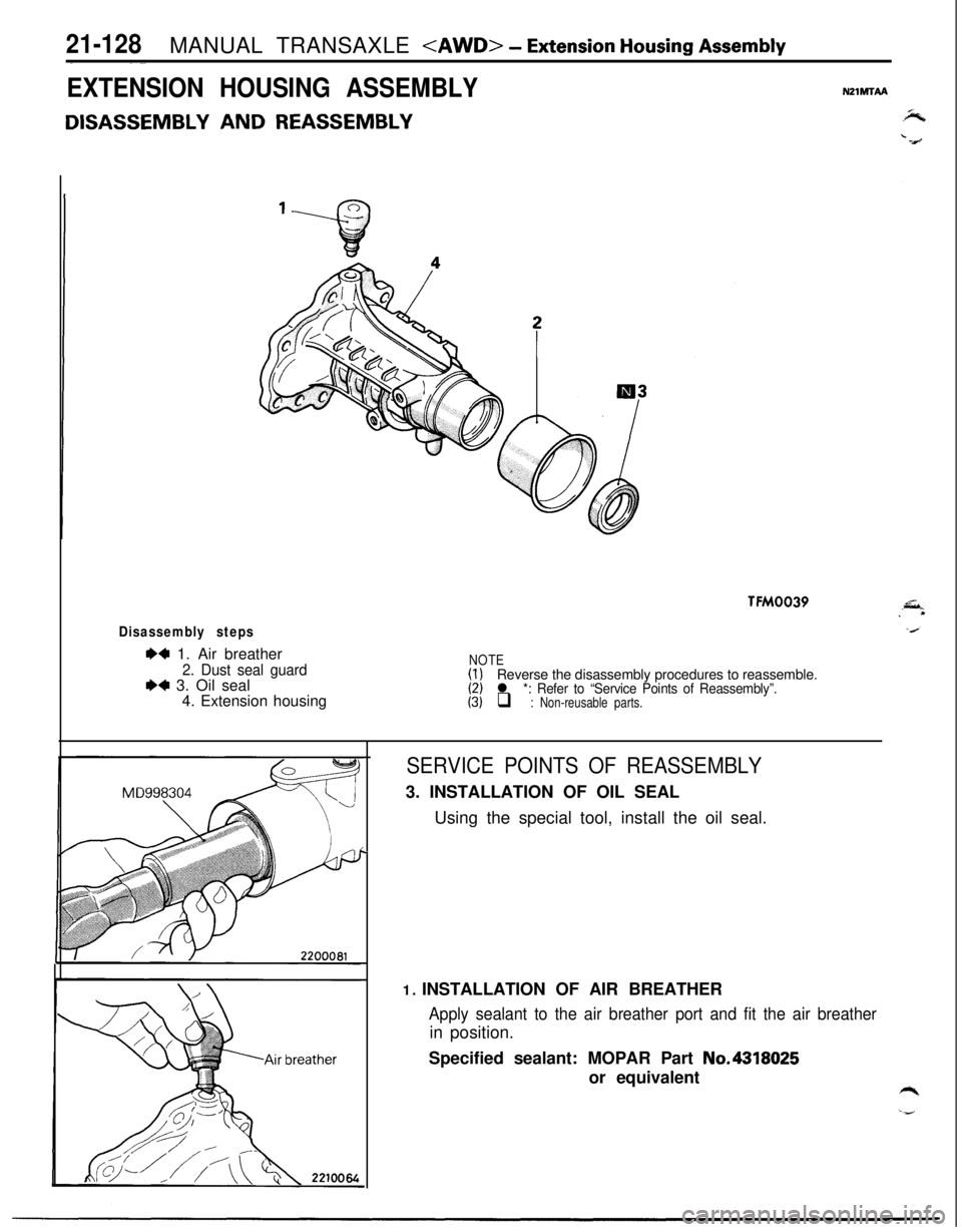
21-128MANUAL TRANSAXLE - Extension Housing Assembly
EXTENSION HOUSING ASSEMBLYN21MTAA
DISASSEMBLY AND REASSEMBLY
TFM0039
Disassembly steps
6+ 1. Air breather
2. Dust seal guardI)+ 3. Oil seal
4. Extension housing
NOTE(I)(2)Reverse the disassembly procedures to reassemble.(3)l *: Refer to “Service Points of Reassembly”.q : Non-reusable parts.
.
SERVICE POINTS OF REASSEMBLY3. INSTALLATION OF OIL SEAL
Using the special tool, install the oil seal.
1. INSTALLATION OF AIR BREATHER
Apply sealant to the air breather port and fit the air breatherin position.
Specified sealant: MOPAR Part No.4318025
or equivalent
Page 823 of 1216
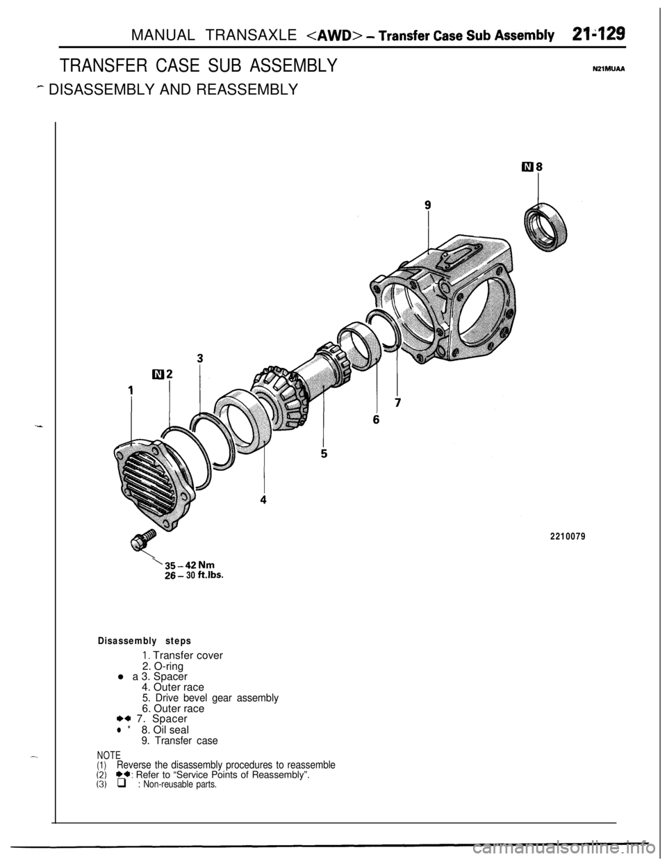
MANUAL TRANSAXLE - Transfer Case Sub Assembly21;129
TRANSFER CASE SUB ASSEMBLYN21MUAA
- DISASSEMBLY AND REASSEMBLY
I-
-2210079
‘35-42Nm26 - 30 ft.lbs.
Disassembly steps
I. Transfer cover
2. O-ring
l a 3. Spacer
4. Outer race
5. Drive bevel gear assembly6. Outer race
*a 7. Spacer
l *8. Oil seal
9. Transfer case
NOTE(1)Reverse the disassembly procedures to reassemble(2)*a: Refer to “Service Points of Reassembly”.(3)q : Non-reusable parts.
Page 824 of 1216
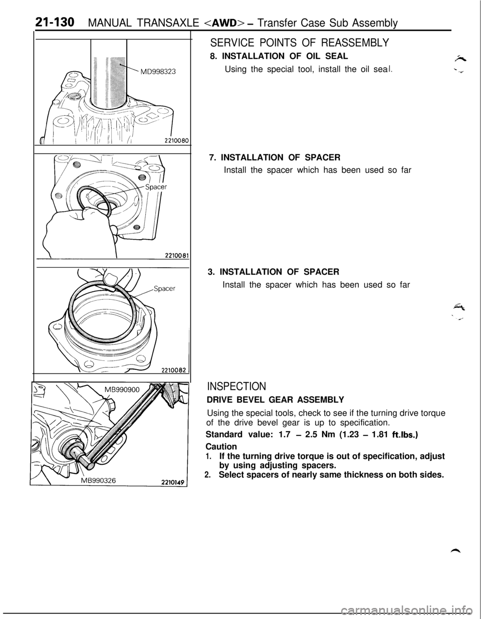
21-130MANUAL TRANSAXLE - Transfer Case Sub Assembly
SERVICE POINTS OF REASSEMBLY8. INSTALLATION OF OIL SEAL
Using the special tool, install the oil sea
jP,
II..-67. INSTALLATION OF SPACER
Install the spacer which has been used so far
3. INSTALLATION OF SPACER
Install the spacer which has been used so far
INSPECTIONDRIVE BEVEL GEAR ASSEMBLY
Using the special tools, check to see if the turning drive torque
of the drive bevel gear is up to specification.
Standard value: 1.7
- 2.5 Nm (1.23 - 1.81 ft.lbs.)Caution
1.If the turning drive torque is out of specification, adjust
by using adjusting spacers.
2.Select spacers of nearly same thickness on both sides.
h
Page 825 of 1216
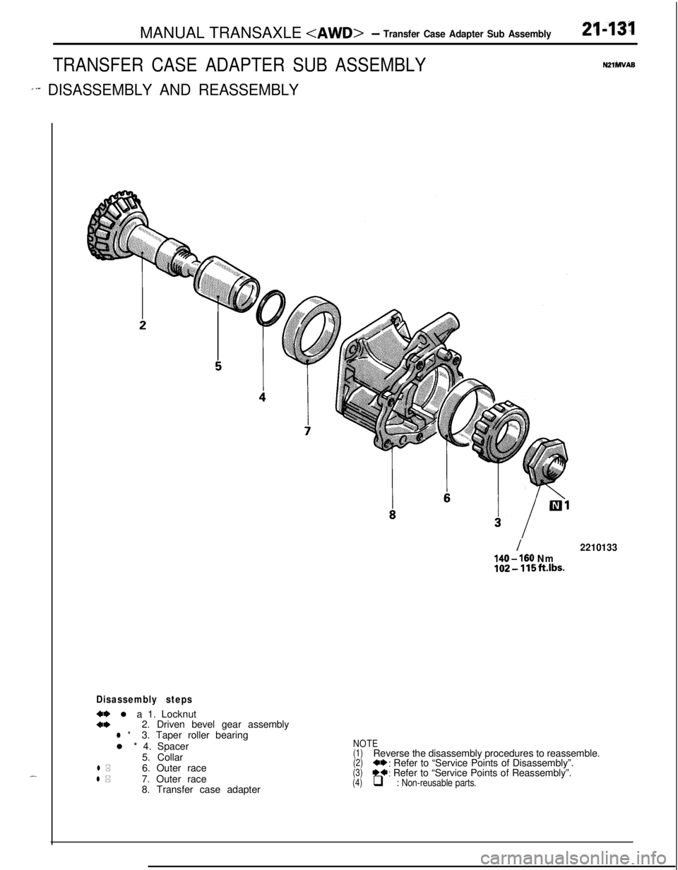
MANUAL TRANSAXLE - Transfer Case Adapter Sub Assembly
TRANSFER CASE ADAPTER SUB ASSEMBLY
1’” DISASSEMBLY AND REASSEMBLY
2143’1
N2lhlVAS.-
Disassembly steps
w l a 1. Locknuta*2. Driven bevel gear assemblyl *3. Taper roller bearing
l * 4. Spacer
5. Collar
l *6. Outer racel *7. Outer race
8. Transfer case adapter
I2210133
140 - 160 Nm102-115ft.lbs.
NOTE(1)Reverse the disassembly procedures to reassemble.(2)+*: Refer to “Service Points of Disassembly”.(3)*+: Refer to “Service Points of Reassembly”.(4)q : Non-reusable parts.
Page 826 of 1216
21-132MANUAL TRANSAXLE - Transfer Case Adapter Sub Assembly
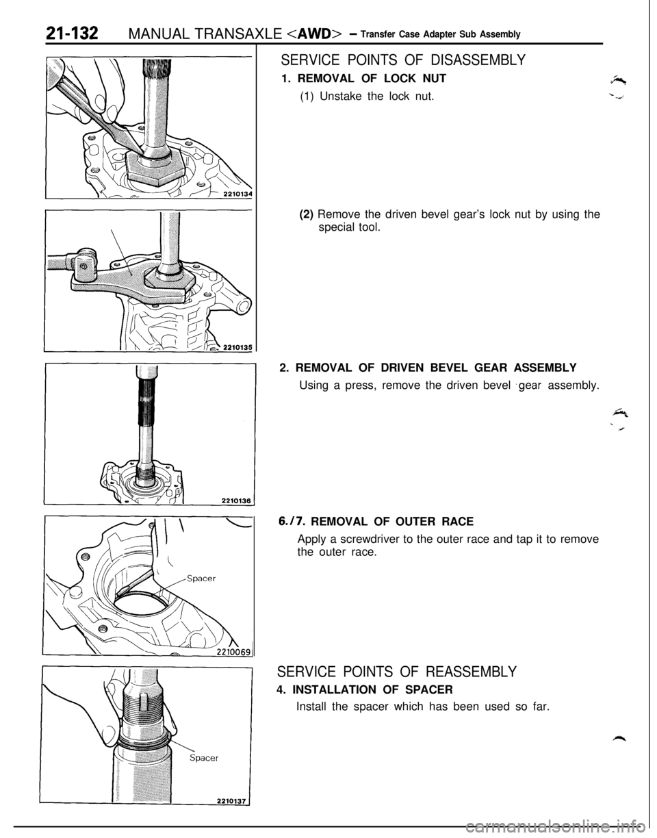
SERVICE POINTS OF DISASSEMBLY1. REMOVAL OF LOCK NUT
(1) Unstake the lock nut.
(2) Remove the driven bevel gear’s lock nut by using the
special tool.
2. REMOVAL OF DRIVEN BEVEL GEAR ASSEMBLY
Using a press, remove the driven bevel
‘gear assembly.6.17. REMOVAL OF OUTER RACE
Apply a screwdriver to the outer race and tap it to remove
the outer race.
SERVICE POINTS OF REASSEMBLY4. INSTALLATION OF SPACER
Install the spacer which has been used so far.
Page 827 of 1216
MANUAL TRANSAXLE - Transfer Case Adapter Sub Assemblyml33
\
BMD9988121 11
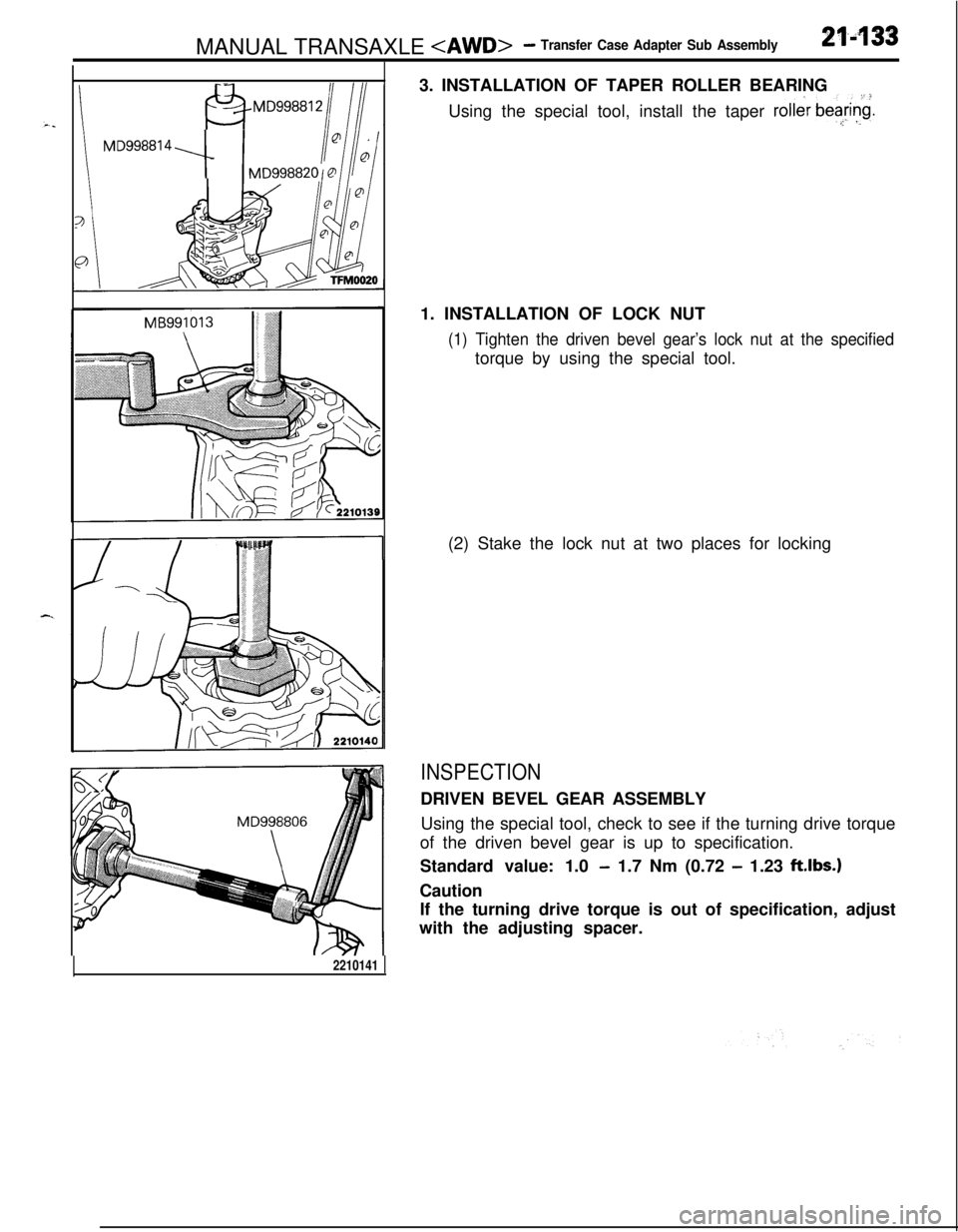
MDgg881 4 --I-3. INSTALLATION OF TAPER ROLLER BEARING
Using the special tool, install the taper
roller bea&.z, ‘.1. INSTALLATION OF LOCK NUT
(1) Tighten the driven bevel gear’s lock nut at the specifiedtorque by using the special tool.
(2) Stake the lock nut at two places for locking
INSPECTIONDRIVEN BEVEL GEAR ASSEMBLY
Using the special tool, check to see if the turning drive torque
of the driven bevel gear is up to specification.
Standard value: 1.0
- 1.7 Nm (0.72 - 1.23 ftlbs.)Caution
If the turning drive torque is out of specification, adjust
with the adjusting spacer.
2210141 1
Page 828 of 1216
21-134MANUAL TRANSAXLE - Drive Bevel Gear Assembly
DRIVE BEVEL GEAR ASSEMBLYNZlMWAA
DISASSEMBLY AND REASSEMBLY
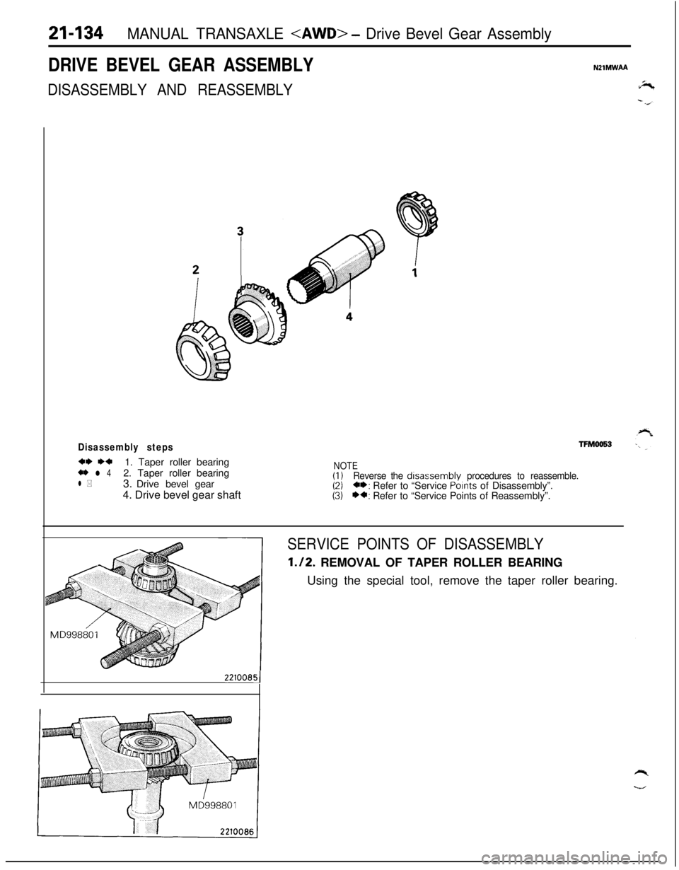
Disassembly steps
4~ WI1. Taper roller bearing+* l 42. Taper roller bearing
3. Drive bevel gearl *4. Drive bevel gear shaft
TFM0053
NOTE(I)Reverse the disassembly procedures to reassemble.(2)**: Refer to “Service Points of Disassembly”.(3)*a: Refer to “Service Points of Reassembly”.
22100851
SERVICE POINTS OF DISASSEMBLY
1.12. REMOVAL OF TAPER ROLLER BEARING
Using the special tool, remove the taper roller bearing.
Page 829 of 1216
MANUAL TRANSAXLE - Drive Bevel Gear Assembly2f-135
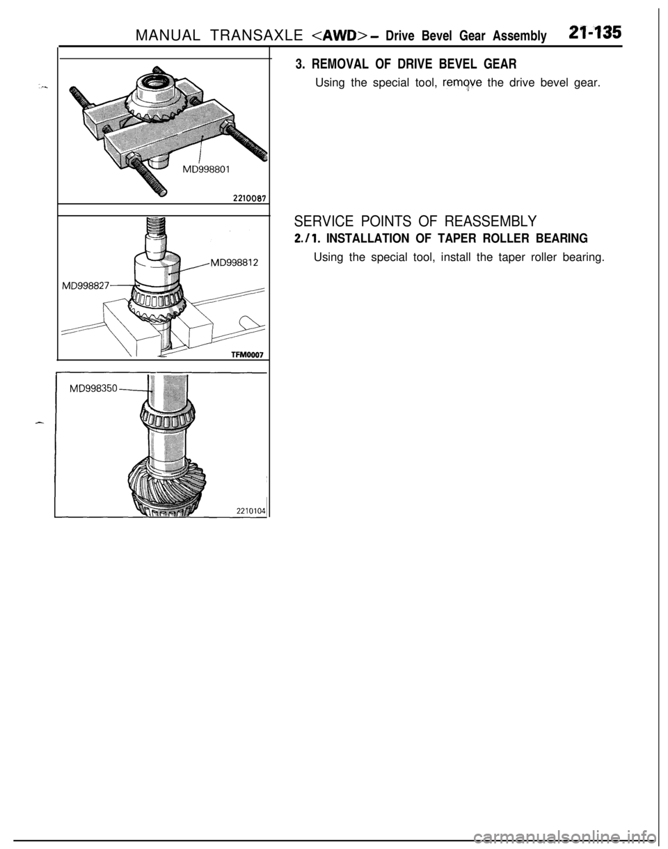
v22100873. REMOVAL OF DRIVE BEVEL GEAR
Using the special tool,
remgve the drive bevel gear.
SERVICE POINTS OF REASSEMBLY
2.11. INSTALLATION OF TAPER ROLLER BEARINGUsing the special tool, install the taper roller bearing.
Page 830 of 1216
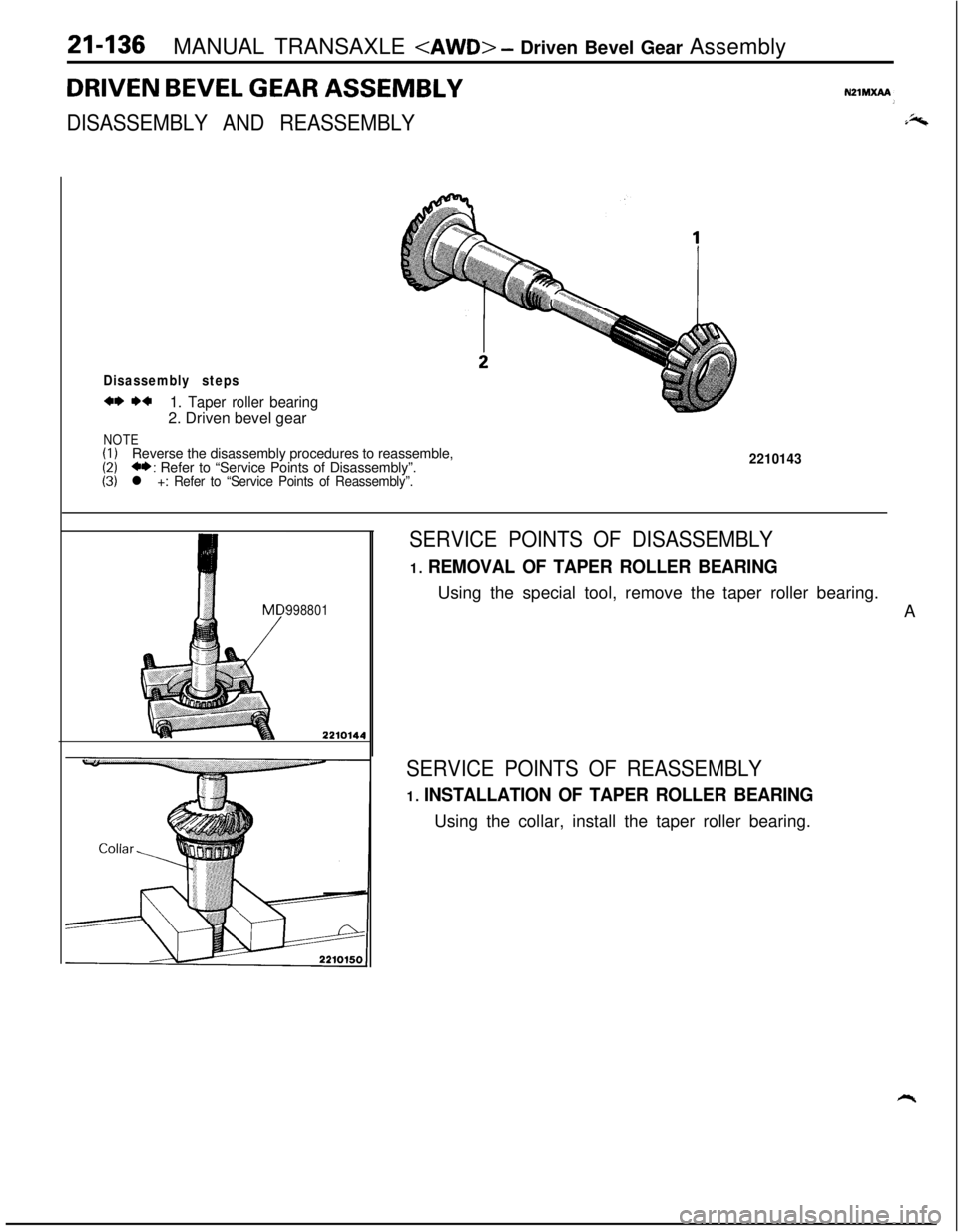
21-136MANUAL TRANSAXLE - Driven Bevel Gear Assembly
DRIVEN BEVEL GEAR ASSEMBLY
DISASSEMBLY AND REASSEMBLY
Disassembly steps
a* I)*1. Taper roller bearing2. Driven bevel gear
NOTE(I)(2)Reverse the disassembly procedures to reassemble,(3)+*: Refer to “Service Points of Disassembly”.l +: Refer to “Service Points of Reassembly”.
2210143
9988012210144
SERVICE POINTS OF DISASSEMBLY
1. REMOVAL OF TAPER ROLLER BEARINGUsing the special tool, remove the taper roller bearing.
A
SERVICE POINTS OF REASSEMBLY
1. INSTALLATION OF TAPER ROLLER BEARINGUsing the collar, install the taper roller bearing.
Trending: automatic transmission, electric, fuel additives, USB, wheel size, alternator belt, engine specifications

