head bolt MITSUBISHI ECLIPSE 1991 Service Manual
[x] Cancel search | Manufacturer: MITSUBISHI, Model Year: 1991, Model line: ECLIPSE, Model: MITSUBISHI ECLIPSE 1991Pages: 1216, PDF Size: 67.42 MB
Page 28 of 1216
28INTRODUCTION AND MASTER TROUBLESHOOTING - Tightening Torque
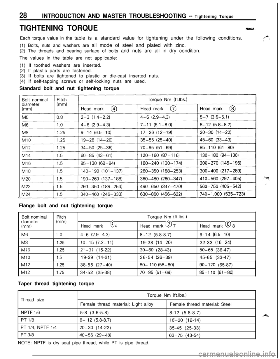
TIGHTENING TORQUENOOJA-Each torque value in the table is a standard value for tightening under the following conditions.
(1) Bolts, nuts and washers are all mode of steel and plated with zinc.
(2) The threads and bearing surface of bolts and nuts are all in dry condition.
The values in the table are not applicable:
(1) If toothed washers are inserted.
(2) If plastic parts are fastened.
(3) If bolts are tightened to plastic or die-cast inserted nuts.
(4) If self-tapping screws or self-locking nuts are used.
Standard bolt and nut tightening torque
I
I
ILFlange bolt and nut tightening torque
Bolt nominal
PitchTorque Nm (ftlbs.)
KTter
(mm)
Headmark0 4Headmark 0 7Headmark 0 8M6
1.o4-6(2.9-4.3)8-l 2(5.8-8.7)9-14(6.5-10)M8
1.25IO-15(7.2-11)19-28(14-20)22-33(16-24)
Ml01.2521-31(15-22)39-60(28-43)50-65(36-47)
Ml01.519-29(14-21)36-54(26-39)45-65(33-47)
Ml21.2538-55(27-40)80- 110 (58-80)90- 120(65-87)
Ml21.7534-52(25-38)70-95 (51-69)85-l 10(61-80)
Taper thread tightening torque
Torque Nm (ftlbs.)
Thread sizeFemale thread material: Light alloy
Female thread material: Steel
NPTF
l/65-8 (3.6-5.8)
8-12 (5.8-8.7)
PT
l/88- 12 (5.8-8.7)16’-20 (12-14)
PT
l/4, NPTF I/420-30 (14-22)
35-45 (25-33)
PT
31840-55 (29-40)60-75 (43-54)
NOTE: NPTF is dry seat pipe thread, while PT is pipe thread.
Page 251 of 1216
COOLING - Specifications7-3
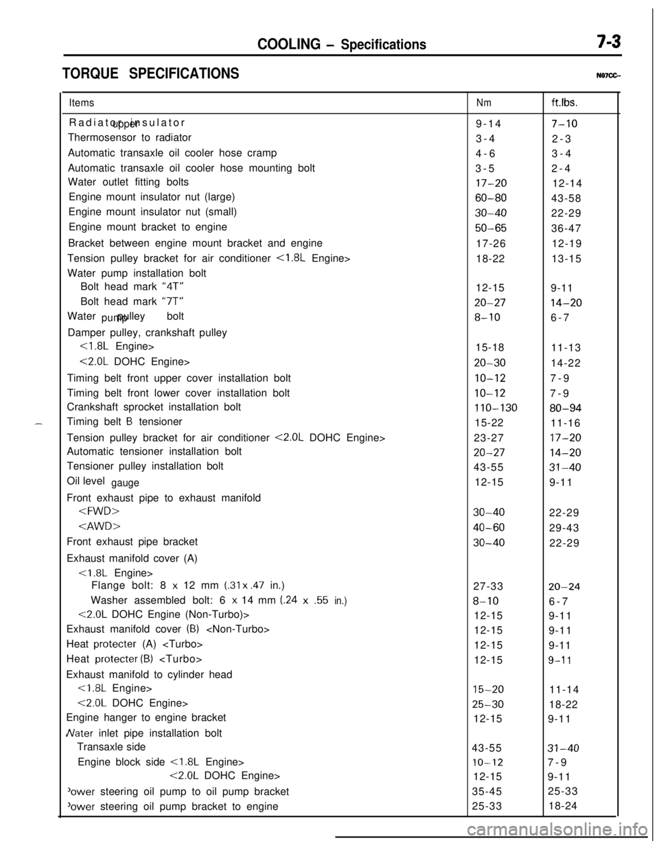
TORQUE SPECIFICATIONSN07CG.
ItemsRadiator insulator
upperThermosensor to radiator
Automatic transaxle oil cooler hose cramp
Automatic transaxle oil cooler hose mounting bolt
Water outlet fitting bolts
Engine mount insulator nut (large)
Engine mount insulator nut (small)
Engine mount bracket to engine
Bracket between engine mount bracket and engine
Tension pulley bracket for air conditioner
<1.8L Engine>
Water pump installation bolt
Bolt head mark “4T”
Bolt head mark “7T”
Water pulley bolt
pumpDamper pulley, crankshaft pulley
<1.8L Engine>
<2.0L DOHC Engine>
Timing belt front upper cover installation bolt
Timing belt front lower cover installation bolt
Crankshaft sprocket installation bolt
Timing belt
B tensioner
Tension pulley bracket for air conditioner
<2.0L DOHC Engine>
Automatic tensioner installation bolt
Tensioner pulley installation bolt
Oil level
gaugeFront exhaust pipe to exhaust manifold
Exhaust manifold cover (A)
Flange bolt: 8
x 12 mm (.31 x .47 in.)
Washer assembled bolt: 6
x 14 mm (.24x.55in.)
<2.0L DOHC Engine (Non-Turbo)>
Exhaust manifold cover
(8)
Heat protecter (A)
Heat protecter
(B)
Exhaust manifold to cylinder head<1.8L Engine>
<2.0L DOHC Engine>
Engine hanger to engine bracket
JVater inlet pipe installation bolt
Transaxle side
Engine block side
<1.8L Engine>
<2.0L DOHC Engine>
'ower steering oil pump to oil pump bracket
‘ower steering oil pump bracket to engine
Nmft.lbs.
9-14
7-103-4
2-3
4-63-4
3-52-4
17-2012-14
60-8043-58
30-4022-29
50-6536-47
17-2612-19
18-2213-15
12-15
9-11
20-2714-20
8-106-7
15-18
11-13
20-3014-22
IO-127-9
10-127-9
110-13080-9415-22
11-16
23-27
17-20
20-2714-2043-55
31-4012-15
9-11
30-4022-29
40-6029-43
30-4022-29
27-33
20-24
8-106-7
12-15
9-11
12-15
9-11
12-15
9-11
12-15
9-l 1
15-2011-14
25-3018-22
12-15
9-11
43-55
31-40
IO-127-9
12-15
9-11
35-4525-33
25-3318-24
Page 302 of 1216
9-18ENGINE - Specifications
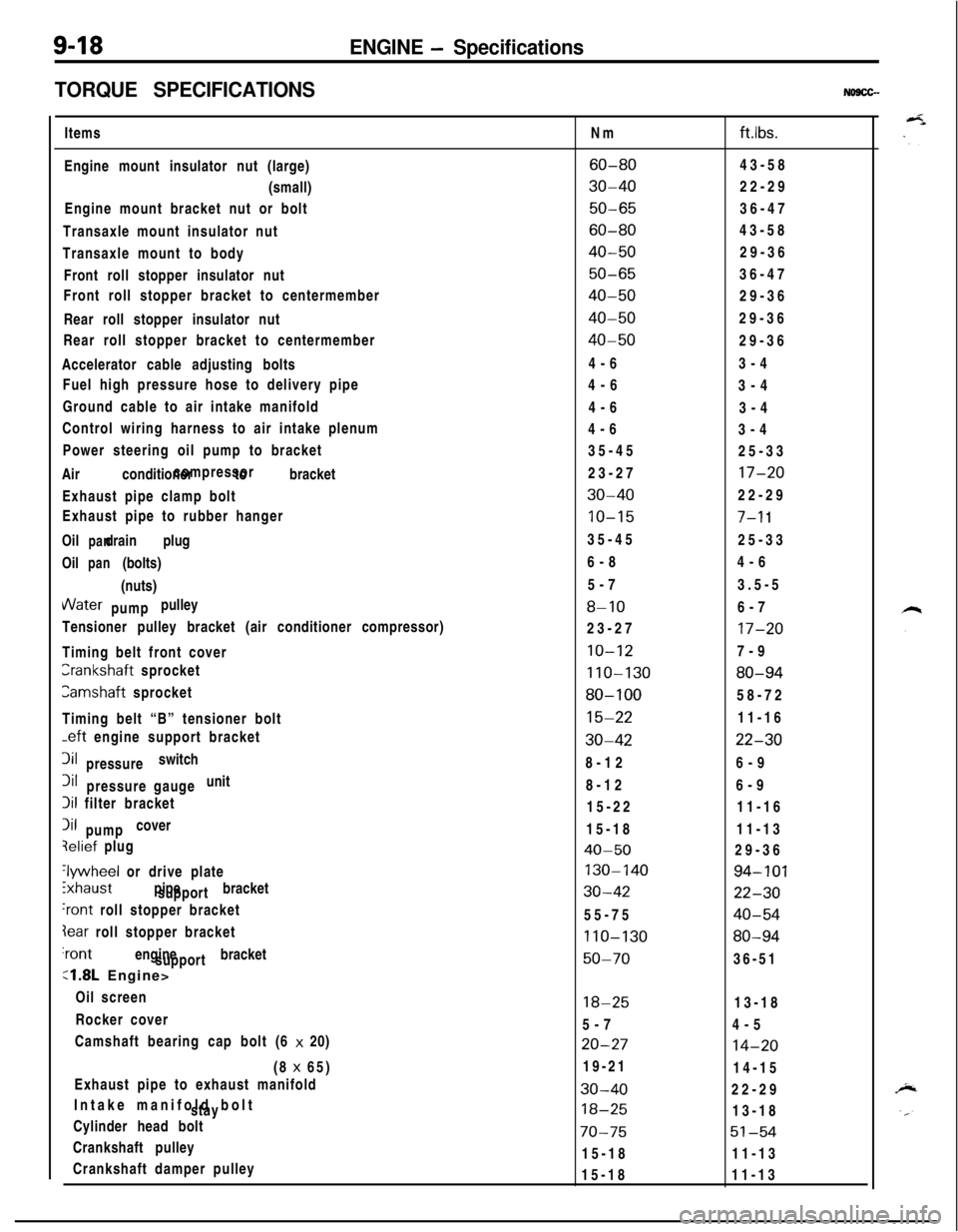
TORQUE SPECIFICATIONS
NO9CG-Items
Engine mount insulator nut (large)
(small)
Engine mount bracket nut or bolt
Transaxle mount insulator nut
Transaxle mount to body
Front roll stopper insulator nut
Front roll stopper bracket to centermember
Rear roll stopper insulator nut
Rear roll stopper bracket to centermember
Accelerator cable adjusting bolts
Fuel high pressure hose to delivery pipe
Ground cable to air intake manifold
Control wiring harness to air intake plenum
Power steering oil pump to bracket
Air conditioner to bracketcompressor
Exhaust pipe clamp bolt
Exhaust pipe to rubber hanger
Oil drain plug
panOil (bolts)
pan(nuts)VVater pulley
pump
Tensioner pulley bracket (air conditioner compressor)
Timing belt front coverCrankshaft sprocket
Camshaft sprocket
Timing belt “B” tensioner bolt
-eft engine support bracket3il switch
pressure3il unit
pressure gauge
Iii filter bracket
Iii cover
pumpqelief plug
‘lywheel or drive plate
ixhaust pipe bracket
support
‘rant roll stopper bracket
Iear roll stopper bracket‘rant engine bracket
support
:1.8L Engine>
Oil screen
Rocker cover
Camshaft bearing cap bolt (6 x 20)
(8 x 65)
Exhaust pipe to exhaust manifold
Intake manifold bolt
stay
Cylinder head bolt
Crankshaft pulley
Crankshaft damper pulleyNm
ftlbs.
60-8043-58
30-4022-29
50-6536-47
60-8043-58
40-5029-36
50-6536-47
40-5029-36
40-5029-36
40-5029-36
4-63-4
4-6
3-4
4-6
3-4
4-6
3-4
35-45
25-33
23-27
17-20
30-4022-29
10-157-l 135-45
25-33
6-84-6
5-73.5-5
8-106-7
23-27
17-20
10-127-9
110-13080-94
80-10058-72
15-2211-16
30-4222-308-126-9
8-126-9
15-2211-16
15-1811-13
40-5029-36
130-14094-101
30-4222-3055-75
40-54
110-13080-94
50-7036-51
18-2513-18
5-74-5
20-2714-2019-21
14-15
30-4022-29
18-2513-18
70-7551-5415-1811-13
15-1811-13
Page 303 of 1216
-
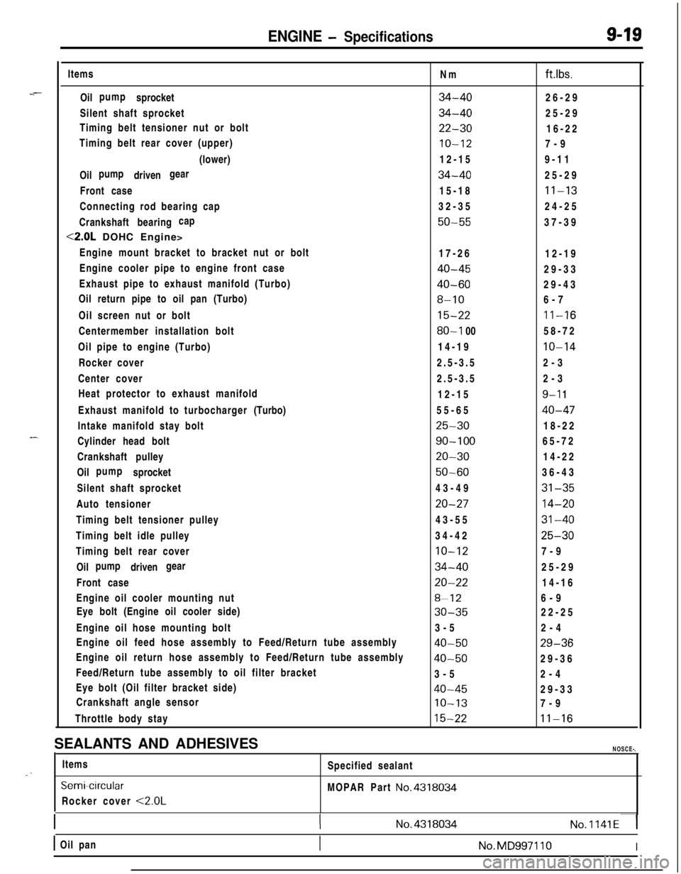
ENGINE - Specifications9-19Items
Oil sprocketpump
Silent shaft sprocket
Timing belt tensioner nut or bolt
Timing belt rear cover (upper)
(lower)
Oil drivenpump gear
Front case
Connecting rod bearing cap
Crankshaft bearingcap
<2.0L DOHC Engine>
Engine mount bracket to bracket nut or bolt
Engine cooler pipe to engine front case
Exhaust pipe to exhaust manifold (Turbo)
Oil return pipe to oil pan (Turbo)
Oil screen nut or bolt
Centermember installation bolt
Oil pipe to engine (Turbo)
Rocker cover
Center cover
Heat protector to exhaust manifold
Exhaust manifold to turbocharger(Turbo)
Intake manifold stay bolt
Cylinder head bolt
Crankshaft pulley
Oil sprocketpump
Silent shaft sprocket
Auto tensioner
Timing belt tensioner pulley
Timing belt idle pulley
Timing belt rear cover
Oil drivenpump gear
Front case
Engine oil cooler mounting nut
Eye bolt (Engine oil cooler side)
Engine oil hose mounting bolt
Engine oil feed hose assembly to Feed/Return tube assembly
Engine oil return hose assembly to Feed/Return tube assembly
Feed/Return tube assembly to oil filter bracket
Eye bolt (Oil filter bracket side)
Crankshaft angle sensor
Throttle body stayNm
ft.lbs.
34-4026-29
34-4025-29
22-3016-22
IO-127-9
12-159-11
34-4025-29
15-18
11-1332-3524-25
50-5537-39
17-26
12-19
40-4529-33
40-6029-43
8-106-7
15-2211-16
80-l 0058-72
14-19
10-142.5-3.52-3
2.5-3.52-3
12-15
9-l 155-65
40-47
25-3018-22
90-10065-72
20-3014-22
50-6036-43
43-49
31-35
20-2714-2043-55
31-4034-42
25-30
10-127-9
34-4025-29
20-2214-16
8-126-9
30-3522-25
3-52-4
40-5029-36
40-5029-36
3-52-4
40-4529-33
IO-137-9
15-2211-16SEALANTS AND ADHESIVES
NOSCE-.Items
Specified sealant
“. _
SemiWrcularMOPAR Part No.4318034Rocker cover
<2.0L
1(No.4318034No.1141~1
1 Oil pan1No.MD997110I
Page 311 of 1216
ENGINE <1.8L Engine> -Service Adjustment Procedures9-27
I.
Timing mark(on upper under cover)Timing belt
Timing mark
A(on camshaft
sprocket)OlR0154
3EN076
3EN07;-
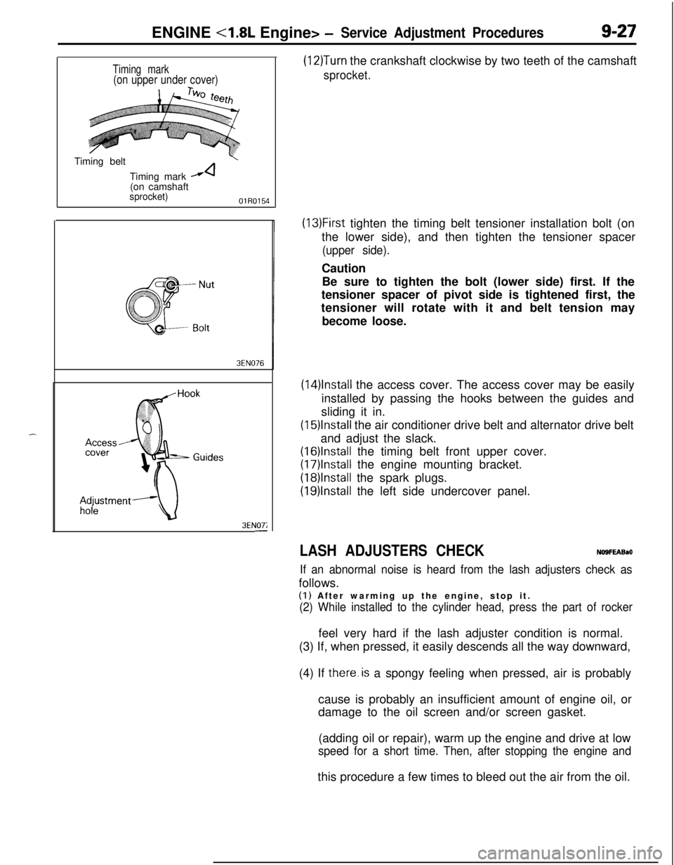
(12)Turn the crankshaft clockwise by two teeth of the camshaft
sprocket.
(13)First tighten the timing belt tensioner installation bolt (on
the lower side), and then tighten the tensioner spacer
(upper side).Caution
Be sure to tighten the bolt (lower side) first. If the
tensioner spacer of pivot side is tightened first, the
tensioner will rotate with it and belt tension may
become loose.
(14)lnstall the access cover. The access cover may be easily
installed by passing the hooks between the guides and
sliding it in.
(15)lnstall the air conditioner drive belt and alternator drive belt
and adjust the slack.
(16)lnstalI the timing belt front upper cover.
(17)lnstall the engine mounting bracket.
(18)lnstalI the spark plugs.
(19)lnstall the left side undercover panel.
LASH ADJUSTERS CHECKNO9FEABaO
If an abnormal noise is heard from the lash adjusters check asfollows.
(I) After warming up the engine, stop it.
(2) While installed to the cylinder head, press the part of rockerfeel very hard if the lash adjuster condition is normal.
(3) If, when pressed, it easily descends all the way downward,
(4) If there.is a spongy feeling when pressed, air is probably
cause is probably an insufficient amount of engine oil, or
damage to the oil screen and/or screen gasket.
(adding oil or repair), warm up the engine and drive at low
speed for a short time. Then, after stopping the engine andthis procedure a few times to bleed out the air from the oil.
Page 323 of 1216
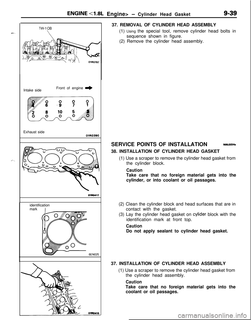
ENGlNE <1.8L Engine> - Cylinder Head Gasket9-3937. REMOVAL OF CYLINDER HEAD ASSEMBLY
(1) Using the special tool, remove cylinder head bolts in
sequence shown in figure.
(2) Remove the cylinder head assembly.
TW-1 OBIntake sideFront of engine
r,Exhaust side
01R0390identification
I
mark
6EN025
Olm415SERVICE POINTS OF INSTALLATION
NO9JDDHs38. INSTALLATION OF CYLINDER HEAD GASKET
(1) Use a scraper to remove the cylinder head gasket from
the cylinder block.
CautionTake care that no foreign material gets into the
cylinder, or into coolant or oil passages.
(2) Clean the cylinder block and head surfaces that are in
contact with the gasket.
(3) Lay the cylinder head gasket on cylider block with the
identification mark at front top.
CautionDo not apply sealant to cylinder head gasket.
37. INSTALLATION OF CYLINDER HEAD ASSEMBLY
(1) Use a scraper to remove the cylinder head gasket from
the cylinder head assembly.
CautionTake care that no foreign material gets into the
coolant or oil passages.
Page 324 of 1216
ENGINE <1.8L Engine> - Cylinder Head Gasket
OlAOlO:Intake sideFront of engine
I,Exhaust side
01R0390
4pply
sealant 1Mating marks
.,
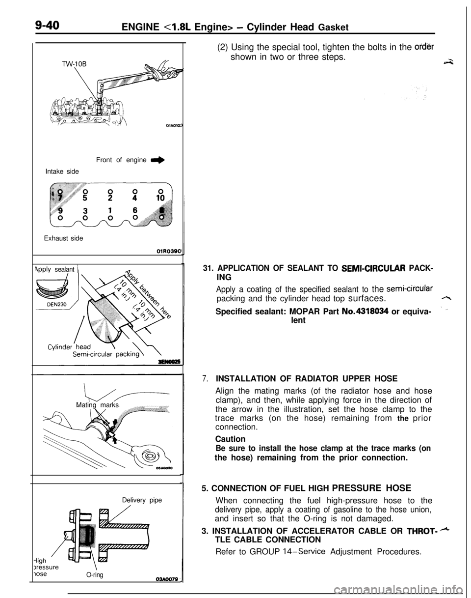
iighDelivery pipe3ressureloseO-ring03Aoo79(2) Using the special tool, tighten the bolts in the
ordershown in two or three steps.
a-2
31. APPLICATION OF SEALANT TO SEMI-CIRCULAR PACK-ING
Apply a coating of the specified sealant to the semi-circularpacking and the cylinder head top surfaces.
/LSpecified sealant: MOPAR Part No.4318034 or equiva-
_ ‘-lent
7.INSTALLATION OF RADIATOR UPPER HOSE
Align the mating marks (of the radiator hose and hose
clamp), and then, while applying force in the direction of
the arrow in the illustration, set the hose clamp to the
trace marks (on the hose) remaining from the prior
connection.
Caution
Be sure to install the hose clamp at the trace marks (onthe hose) remaining from the prior connection.
5. CONNECTION OF FUEL HIGH PRESSURE HOSE
When connecting the fuel high-pressure hose to the
delivery pipe, apply a coating of gasoline to the hose union,and insert so that the O-ring is not damaged.
3. INSTALLATION OF ACCELERATOR CABLE OR
THROT- +TLE CABLE CONNECTION
Refer to GROUP
14-Service Adjustment Procedures.
Page 334 of 1216
S-50 ENGINE 4.8L Engine> -Rocker Arms, Rocker Arm Shafts and Camshaft
MD998443Lash adjuster
6EN248Apply sealant
DEN230
10 mm
3EN0044
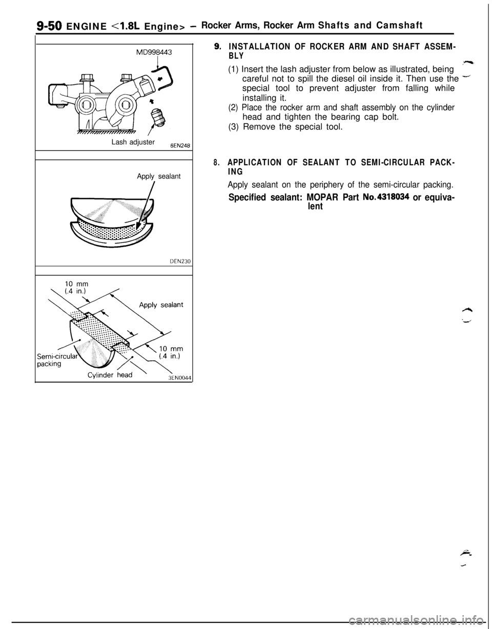
9.INSTALLATION OF ROCKER ARM AND SHAFT ASSEM-
BLY(1) Insert the lash adjuster from below as illustrated, being
*-careful not to spill the diesel oil inside it. Then use the
+special tool to prevent adjuster from falling while
installing it.
(2) Place the rocker arm and shaft assembly on the cylinderhead and tighten the bearing cap bolt.
(3) Remove the special tool.
8.APPLICATION OF SEALANT TO SEMI-CIRCULAR PACK-
ING
Apply sealant on the periphery of the semi-circular packing.
Specified sealant: MOPAR Part No.4318034 or equiva-
lent
Page 337 of 1216
ENGINE <1.8L Engine>- Cylinder Head and Valve9-53
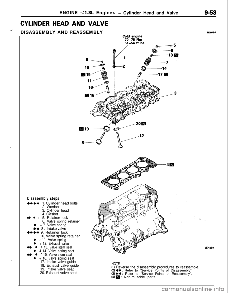
CYLINDERHEADAND VALVE
-’DISASSEMBLY AND REASSEMBLYNDSPE-A
C;;d ;;g$;
51154 ftlbs.
&
, tP-----5
1g-.-a
105 y----2g&---l4
Disassembly steps
+e ~~I. Cylinder head bolts
2. Washer
3. Cylinder head4. Gasket
+e l +5. Retainer lock
6. Valve spring retainer
l + 7. Valve spring
~~ 8. Intakevalve+e e+ 9. Retainer lock10. Valve spring retainer
l a 11. Valve springl + 12. Exhaust valve+* l 4 13. Valve stem seall 4 14. Valve spring seat4I) l * 15. Valve stem seall + 16. Valve spring seat17. Intake valve guide
18. Exhaust valve guide
19. Intake valve seat20. Exhaust valve seatNOTE(I) Reverse the disassembly procedures to reassemble.(2) +e : Refer to “Service Points of Disassembly”.(3) ~~ : Refer to “Service Points of Reassembly”.(4) m : Non-reusable parts
3EN289
Page 338 of 1216
ENGINE - Cylinder Head and ValveSERVICE POINTS OF DISASSEMBLY
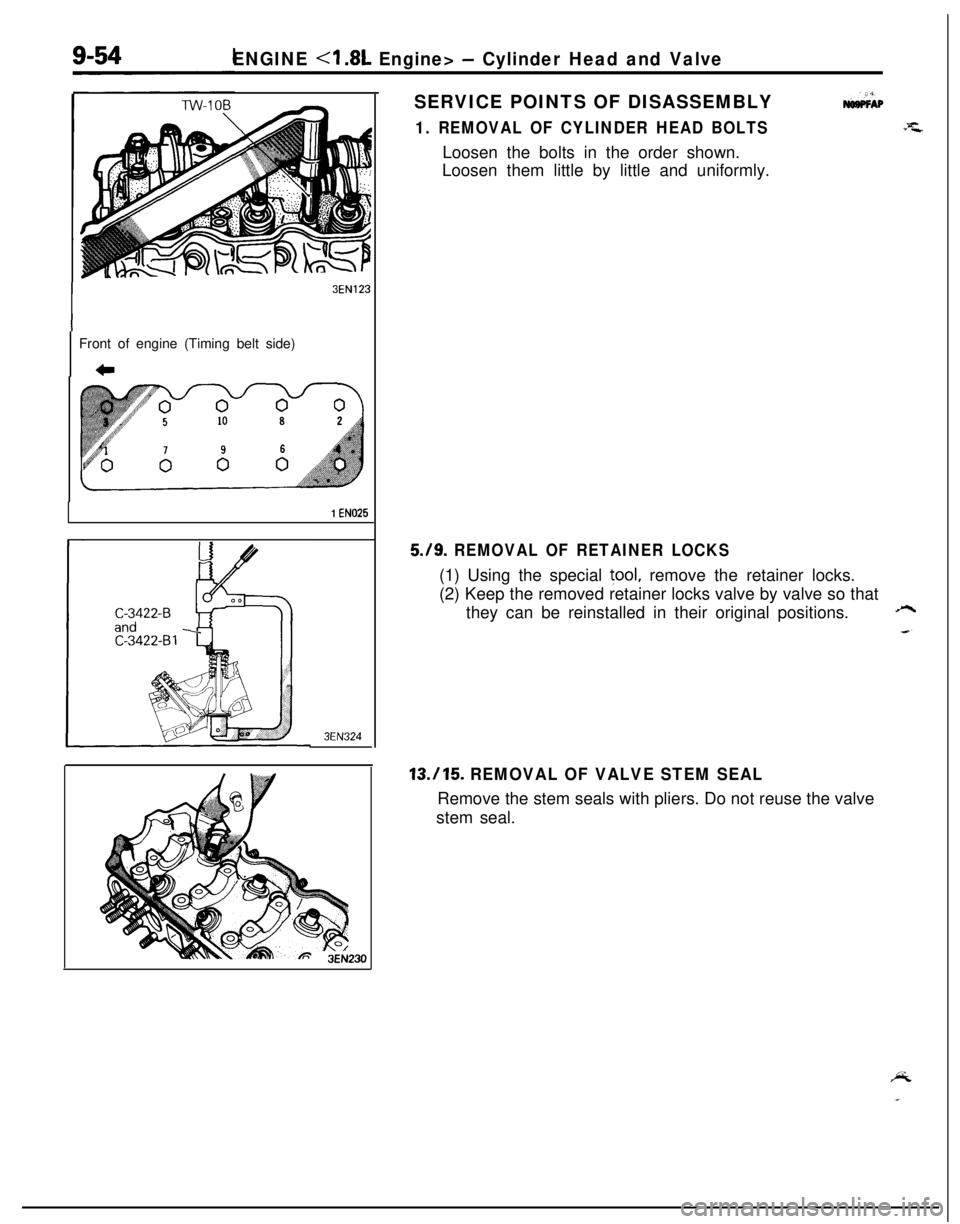
1. REMOVAL OF CYLINDER HEAD BOLTS
3EN123Front of engine (Timing belt side)
c
1 EN025
3EN324Loosen the bolts in the order shown.
Loosen them little by little and uniformly.
5./9. REMOVAL OF RETAINER LOCKS(1) Using the special
tool, remove the retainer locks.
(2) Keep the removed retainer locks valve by valve so that
they can be reinstalled in their original positions.
A
13.115. REMOVAL OF VALVE STEM SEALRemove the stem seals with pliers. Do not reuse the valve
stem seal.