heater MITSUBISHI ECLIPSE 1991 Service Manual
[x] Cancel search | Manufacturer: MITSUBISHI, Model Year: 1991, Model line: ECLIPSE, Model: MITSUBISHI ECLIPSE 1991Pages: 1216, PDF Size: 67.42 MB
Page 1 of 1216
BACKUPGROUP INDEX &ma
;r Service Manual
LASER
TALON
1991
Volume-l
Engine, Chassis
& Body
FOREWORDThis Service Manual has been prepared with the
latest service information available at the time of
‘* publication.It is subdivided into various group
categories and each section contains diagnosis,
disassembly, repair, and installation procedures
along with complete specifications and tightening
references. Use of this manual will aid in properly
performing any servicing necessary to maintain or
restore the high levels of performance and reliabilitydesigned into these outstanding vehicles.
This BACKUP DSM manual IS to be used ONLY as a BACKUP. Please DO NOT REDISTRIBUTEWHOLE SECTIONS. This BACKUP was sold to you under the fact that you do indeed OWNa GENUINE DSM MANUAL. It CANNOT BE considered a REPLACEMENT (Unless your originalmanual was lost or destroyed.)Please See
README.N or README.HTML for additional information
Thank you. G~mm~emymanual@hotma~l.com
1,
wA
CHRYSLER
CORPORATION
Chrysler Corporation reserves the right to make changes in design 0’: tomake additions to or improvements in its products without lmqoslngd ., . any obligations upon itself to install them on its products previouslymanufactured.
0 1990 Mitsubishi Motors CorporationPrinted in U.S.A.Introduction and
Master
Troubleshooting. . . . . .,. . . . . . . . . r...m,
Lubrication and Maintenance . . . . . . . . ‘-0‘8
; “. i,
.Front Suspension. . . . . . . . . . . . . . ..*............d...Rear Axle
. . . . . . . . . . . . . . . . . . . . . . . . . . . . ..‘.....................
/
ServiceBrakes-Parking. . . . . . . . . . . . . . . . . . . . . . . . . . . . . . . . . . . . . .
Clutch. . . . . . . . . . . . . . . . . . . . . . . . . . . . . . . . . ..~......................‘t.
Cooling. . . . . . . . . . . . . . . . . ..i....................................
,., .‘,-,
Engine..i....~....r...............~....~.*,.~.~.~,‘~~...;..~~..Intake and Exhaust
. . . . . . ..L....................Fuel System
. . . . . . . . . . . ..ti.......r................~...Propeller Shaft
.......................................IRear
Suspensiori.............................y.f...
ManualSteering- Power.....................................Manual
I
transaxle-Automatic .............:;i...,;.....;Wheels
and Tires.................................
Body.............................................................Heater & Air Conditioning
..............Emission
Contr6l Systems..............
INOTE: For Electrical, refer toVolume-2 “Electrical”.
Page 39 of 1216
LUBRICATION AND MAINTENANCE - Recommended Lubrie’ntsand Lubrtcant Capacttles Table
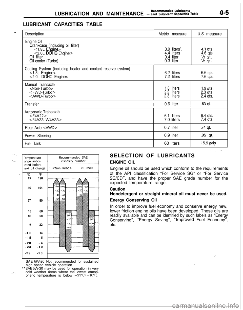
LUBRICANT CAPACITIES TABLE
Description
Engine Oil Engine Oil
Crankcase (including oil filter) Crankcase (including oil filter)
<1.8L Engine><1.8L Engine><2.0L DOHC Engine><2.0L DOHC Enaine>Oil filter Oil filter
Oil cooler (Turbo) Oil cooler (Turbo)
Metric measureU.S. measure
3.9 liters’.4.4 liters
0.4 liter
0.3 liter
4.‘1 qts.4.6 qts.
‘h qt.Y2 qt.
Cooling System (including heater and coolant reserve system)
<2.0L DOHC Engine>6.2 liters
7.2 liters6.6
qts.
7.6 qts.
Manual Transaxle
1.8liters1.9qts.2.2liters2.3qts.
2.3liters
2.4qts.
Transfer
I0.6 literI.63 qt.
Au:oFmqaAtF2pnsaxle
Rear Axle
Power Steering
Fuel Tank
"C“F4912040
104
27
80
1660
1050
032-10
14-15
5-20-4
-23-10
-29-20
6.1 liters6.4 qts.
7.0 liters7.4 qts.
0.7 liter.74 qt.
0.9 liter.95 sf.60 liters
15.9 gal?.
’ ~ “.SELECTION OF LUBRICANTS
ENGINE OIL
Engine oil should be used which conform to the requirements
of the API classification “For Service SG” or “For Service
SGKD”, and have the proper SAE grade number for the
expected temperature range.
Caution
Nondetergent or straight mineral oil must never be used.
Energy Conserving Oil
In order to improve fuel economy and conserve energy new,
lower friction engine oils have been developed. These oils are
readily available and can be identified by such labels as “EnergyConserving”,“Energy Saving”,“Improved Fuel Economy”,
etc.
/”SAE
5W-20 Not recommended for sustained
high speed vehicle operation.**SAE
5W-30 may be used for operation in very
cold weather areas where the lowest atmos-
pheric temperature is below
-23°C (-10°F).
Page 46 of 1216
LUBRICATION AND MAINTENANCE - Maintenance Service
L-4GoodOOA0051C9FW1014K512(9) Supply 4 liters (8.5 pints) of specified ATF into case
through dipstick hole. [Total quantity of ATF required is
6.1 liters (12.9 pints).
Actually however, approx. 4.5 liters (9.5 pints) of fluid
can be replaced because rest of fluid remains in torque
converter.]Specified fluid: MOPAR ATF PLUS (Automatic
Transmission Fluid Type 7176) or
Dia ATF SP or Equivalent
(10)Start engine and allow to idle for at least two minutes.
Then, with parking brake on, move selector lever
momentarily to each position, ending in “N” Neutral
position.
(1 l)Add sufficient ATF to bring fluid level to lower mark.
Recheck fluid level after transaxle is at normal operating
temperature.
Fluid level should be between upper and lower marks of“HOT” range. Insert dipstick fully to prevent dirt from
entering transaxle.
11 .ENGINE COOLANT (Change)NOOSBEAcCheck the cooling system parts, such as radiator, heater,
and oil cooler hoses, thermostat and connections for
leakage and damage.
CHANGE COOLANT
1. Remove the radiator cap.
2. Loosen the drain plug to drain the coolant.
3. Drain the coolant from the reserve tank.
4. After draining the coolant, tighten the drain plug
securely.
5.Supply the coolant into the radiator until it is filled up to
its filler neck.
6. Supply the coolant into the reserve tank.
7. After warming the engine until the thermostat opens,
remove the radiator cap and check the coolant level.
8.Supply the coolant into the radiator until it is filled up to
its filler neck, and install the
.radiator, cap securely.
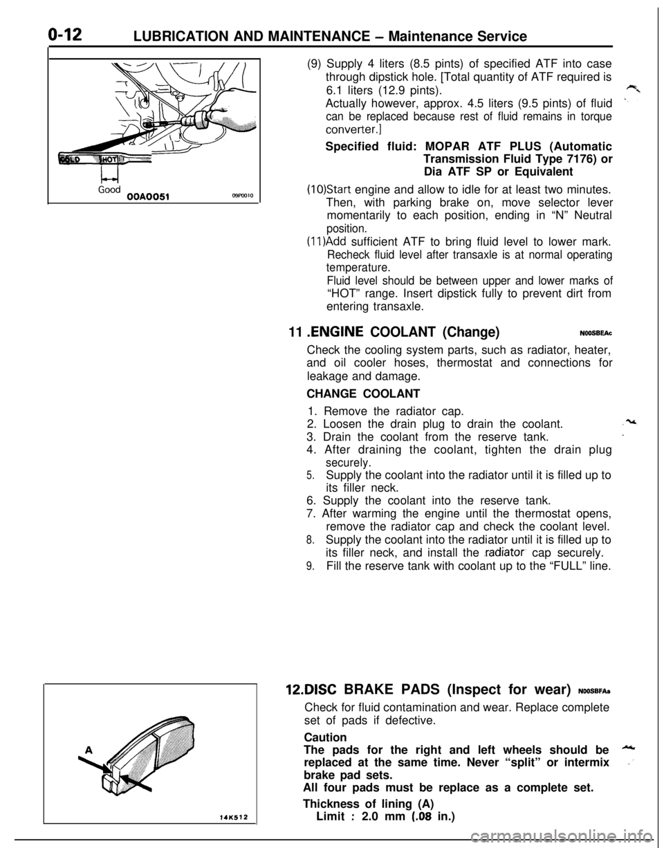
9.Fill the reserve tank with coolant up to the “FULL” line.12DISC BRAKE PADS (Inspect for wear)
NOOSBFA~Check for fluid contamination and wear. Replace complete
set of pads if defective.
Caution
The pads for the right and left wheels should be
replaced at the same time. Never “split” or intermix
brake pad sets.
All four pads must be replace as a complete set.
Thickness of lining (A)
Limit
:2.0 mm (.08 in.)
Page 253 of 1216
COOLING - Troubleshootina7-5
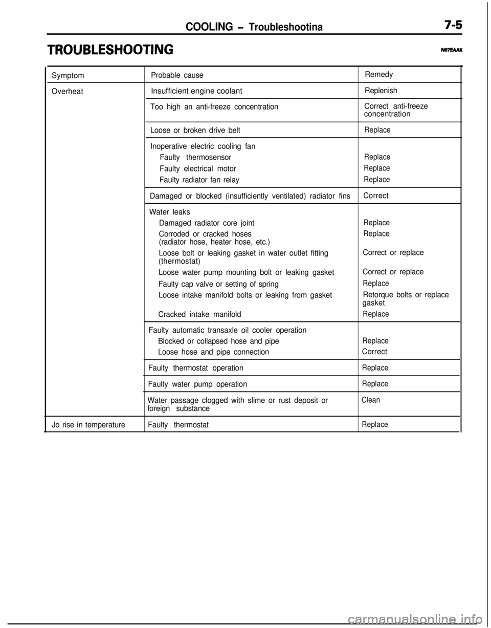
TRO,UBLESHOOTlNG
Symptom
OverheatProbable causeInsufficient engine coolant
Too high an anti-freeze concentrationRemedy
Replenish
Correct anti-freeze
concentration
Loose or broken drive belt
Replace
Inoperative electric cooling fan
Faulty thermosensor
Replace
Faulty electrical motorReplace
Faulty radiator fan relayReplace
Damaged or blocked (insufficiently ventilated) radiator finsCorrect
Water leaks
Damaged radiator core joint
Replace
Corroded or cracked hosesReplace
(radiator hose, heater hose, etc.)
Loose bolt or leaking gasket in water outlet fitting
(thermostat)
Loose water pump mounting bolt or leaking gasket
Faulty cap valve or setting of spring
Loose intake manifold bolts or leaking from gasket
Cracked intake manifold
Faulty automatic transaxle oil cooler operation
Blocked or collapsed hose and pipe
Loose hose and pipe connection
Faulty thermostat operation
Faulty water pump operation
Water passage clogged with slime or rust deposit or
foreign substanceCorrect or replace
Correct or replace
Replace
Retorque bolts or replace
gasket
Replace
Replace
Correct
Replace
Replace
Clean
Jo rise in temperatureFaulty thermostatReplace
Page 274 of 1216
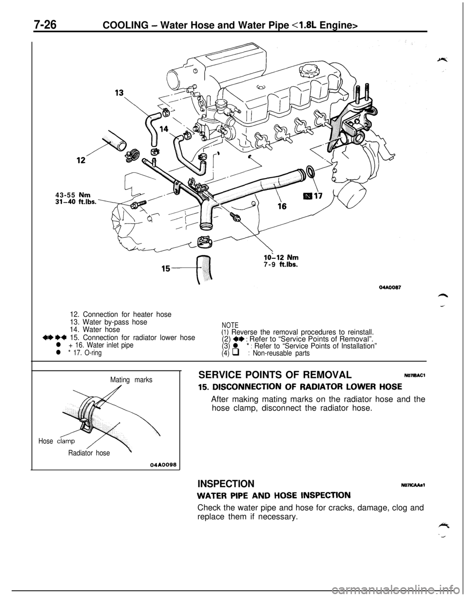
7-26COOLING - Water Hose and Water Pipe <1.8L Engine>
43-55 Nm
31-40 ft.lbs.
lo‘-12 Nm
7-9 ft.lbs.
12. Connection for heater hose
13. Water by-pass hose
14. Water hose
++ e+ 15. Connection for radiator lower hosel + 16. Water inlet pipe
l * 17. O-ring
NOTE(1) Reverse the removal procedures to reinstall.(2) +e : Refer to “Service Points of Removal”.(3) l * : Refer to “Service Points of Installation”(4) q : Non-reusable parts
Mating marks
Hose
Radiator hose’
04AOOSSSERVICE POINTS OF REMOVAL
NO7ISACl
15. DISCONNECTION OF RADIATOR LOWER HOSEAfter making mating marks on the radiator hose and the
hose clamp, disconnect the radiator hose.
INSPECTIONNO7KAAaI
WATER PIPE AND HOSE INSPECTIONCheck the water pipe and hose for cracks, damage, clog and
replace them if necessary.
Page 277 of 1216
,-
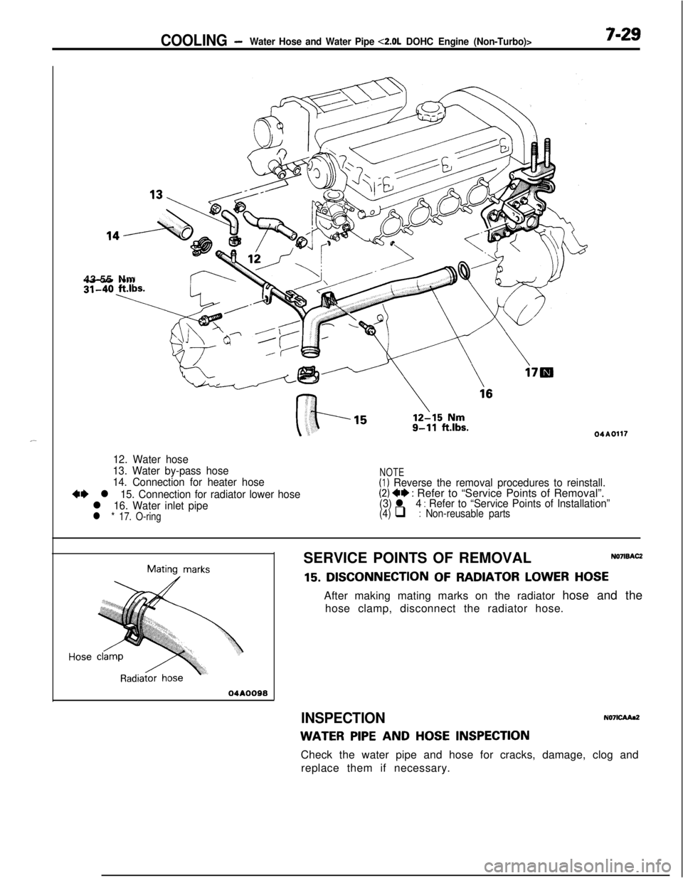
COOLING -Water Hose and Water Pipe <2.0L DOHC Engine (Non-Turbo)>7-2943-55 Nm
04A0117
12. Water hose
13. Water by-pass hose
14. Connection for heater hose
+I) l 15. Connection for radiator lower hose
l 16. Water inlet pipel * 17. O-ring
NOTE(1) Reverse the removal procedures to reinstall.(2) 4* : Refer to “Service Points of Removal”.(3) l 4 : Refer to “Service Points of Installation”(4) q : Non-reusable parts
Mating marks
04AOO98SERVICE POINTS OF REMOVAL
NO’IISACZ
15. DISCONNECTION OF RADIATOR LOWER HOSEAfter making mating marks on the radiator hose and the
hose clamp, disconnect the radiator hose.
INSPECTIONN071CAAa2
WATER PIPE AND HOSE INSPECTIONCheck the water pipe and hose for cracks, damage, clog and
replace them if necessary.
Page 280 of 1216
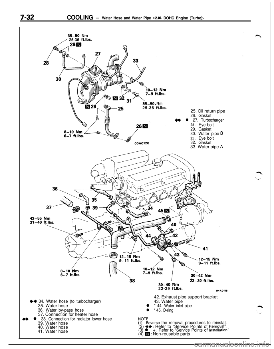
7-32COOLING -Water Hose and Water Pipe <2.0L DOHC Engine (Turbo)>
35-50 Nm/ 25-36 ft.lbs.
35-50 Nm-- - _ . __._25-36 ft.lbs.25. Oil return pipe
26.Gasket
++ l 27. Turbocharger
28.Eye bolt29.Gasket
30.Water pipe631.Eye bolt32.Gasket33. Water pipe A
++ 34. Water hose (to turbocharger)35. Water hose
36. Water by-pass hose37. Connection for heater hose
+e l 38. Connection for radiator lower hose39. Water hose
40. Water hose
41. Water hose
22-30 ft.lbs.30-40 Nm
22-29 ft.lbs.04A011642. Exhaust pipe support bracket
43. Water pipe
l * 44. Water inlet pipe
l * 45. O-ring
FFTkeverse the removal procedures to reinstall.(2) a+ : Refer to “Service Points of Removal”.(3) l + : Refer to “Service Points of Installation”(4) m : Non-reusable parts
Page 315 of 1216
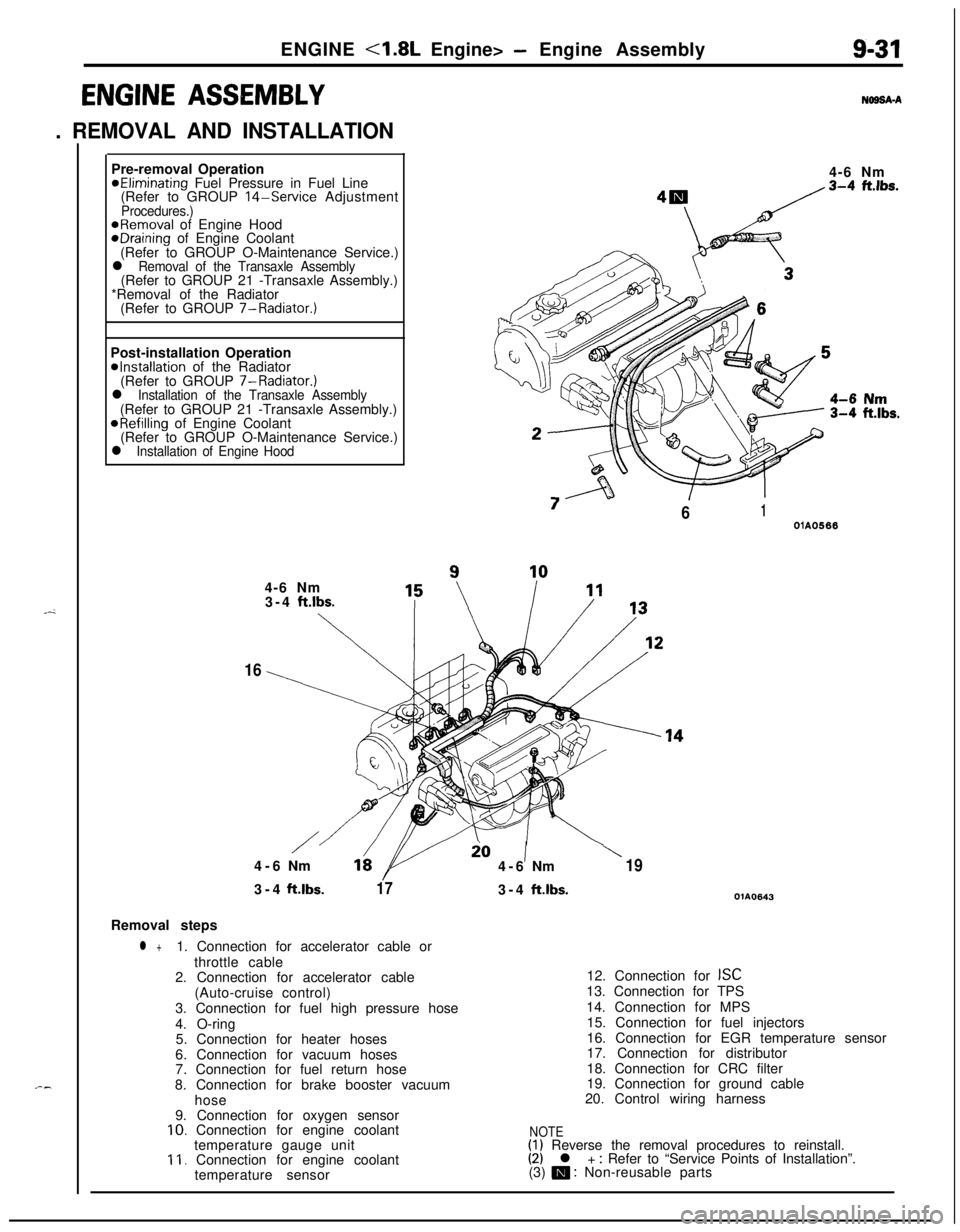
ENGINE <1.8L Engine> - Engine Assembly9-31
ENGINE ASSEMBLY
. REMOVAL AND INSTALLATION
N69SA-APre-removal Operation
@Eliminating Fuel Pressure in Fuel Line
(Refer to GROUP 14-Service AdjustmentProcedures.)@Removal of Engine HoodeDraining of Engine Coolant
(Refer to GROUP O-Maintenance Service.)
l Removal of the Transaxle Assembly(Refer to GROUP 21 -Transaxle Assembly.)
*Removal of the Radiator
(Refer to GROUP 7-Radiator.)
Post-installation Operation
@Installation of the Radiator
(Refer to GROUP 7-Radiator.)
l Installation of the Transaxle Assembly(Refer to GROUP 21 -Transaxle Assembly.)
@Refilling of Engine Coolant
(Refer to GROUP O-Maintenance Service.)
l Installation of Engine Hood4-6 Nm
“7
/61OlA05664-6 Nm
3-4
ft.lbs.
\
16
/io1\4-6Nm164-6Nm193-4ft.lbs.
173-4ft.lbs.OlA0643Removal steps
l +1. Connection for accelerator cable or
throttle cable
2. Connection for accelerator cable
(Auto-cruise control)
3. Connection for fuel high pressure hose
4. O-ring
5. Connection for heater hoses
6. Connection for vacuum hoses
7. Connection for fuel return hose
8. Connection for brake booster vacuum
hose
9. Connection for oxygen sensor
10. Connection for engine coolant
temperature gauge unit
11. Connection for engine coolant
temperature sensor12. Connection for
ISC13. Connection for TPS
14. Connection for MPS
15. Connection for fuel injectors
16. Connection for EGR temperature sensor
17. Connection for distributor
18. Connection for CRC filter
19. Connection for ground cable
20. Control wiring harness
NOTE(1) Reverse the removal procedures to reinstall.(2) l + : Refer to “Service Points of Installation”.
(3) m : Non-reusable parts
Page 320 of 1216
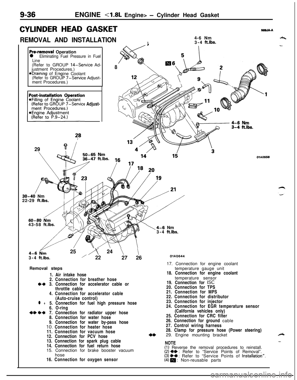
9-36ENGINE
CYLINDER HEAD GASKET
REMOVAL AND INSTALLATION4-6 Nm
73-4 ft.lbs.
NWJA-A
Pre-removal Operationl Eliminating Fuel Pressure in Fuel
Line(Refer to GROUP
14-Service Ad-
justment Procedures.)*Draining of En
ine Coolant
(Refer to GRO9P -/-Service Adjust-ment Procedures.)
(Refer to GROUP
7-Service Adjust-~~~~~~~n
?*
29?i
8
30-46 Nm
22-29 ft.lbs.
60-80 ium43-58 ftlbs.25
iy 24 \\3-4
ftlbs./2227 26
Removal steps
1. Air intake hose
2. Connection for breather hose
I)43. Connection for accelerator cable or
throttle cable
4. Connection for accelerator cable
(Auto-cruise control)
l +5. Connection for fuel high pressure hose
6. O-ring
+e W7. Connection for radiator upper hose
8. Connection for water hose
9. Connection for water by-pass hose
10. Connection for heater hose
11. Connection for vacuum hose
12. Connection for PCV hose
13. Connection for spark plug cable
14. Connection for fuel return hose
15. Connection for brake booster vacuum
hose
16. Connection for oxygen sensor
1\4-6 Nm
3-4 ftlbs.
OlAO556
QlAO64417. Connection for engine coolant
temperature gauge unit
18. Connection for engine coolant
temperature sensor
19. Connection for
ISC20. Connection for TPS
21. Connection for MPS
22. Connection for distributor
23. Connection for injector
24. Connection for EGR temperature sensor
(California vehicles only)
25. Connection for CRC filter
26. Connection for ground cable
27. Control wiring harness
28. Clamp for pressure hose (Power steering)
29. Engine mounting bracket
NOTE
(I) Reverse the removal procedures to reinstall.(2) Ce : Refer to “Service Points of Removal”.(3) ++ : Refer to “Service Points of Installation”.(4) m : Non-reusable parts
Page 365 of 1216
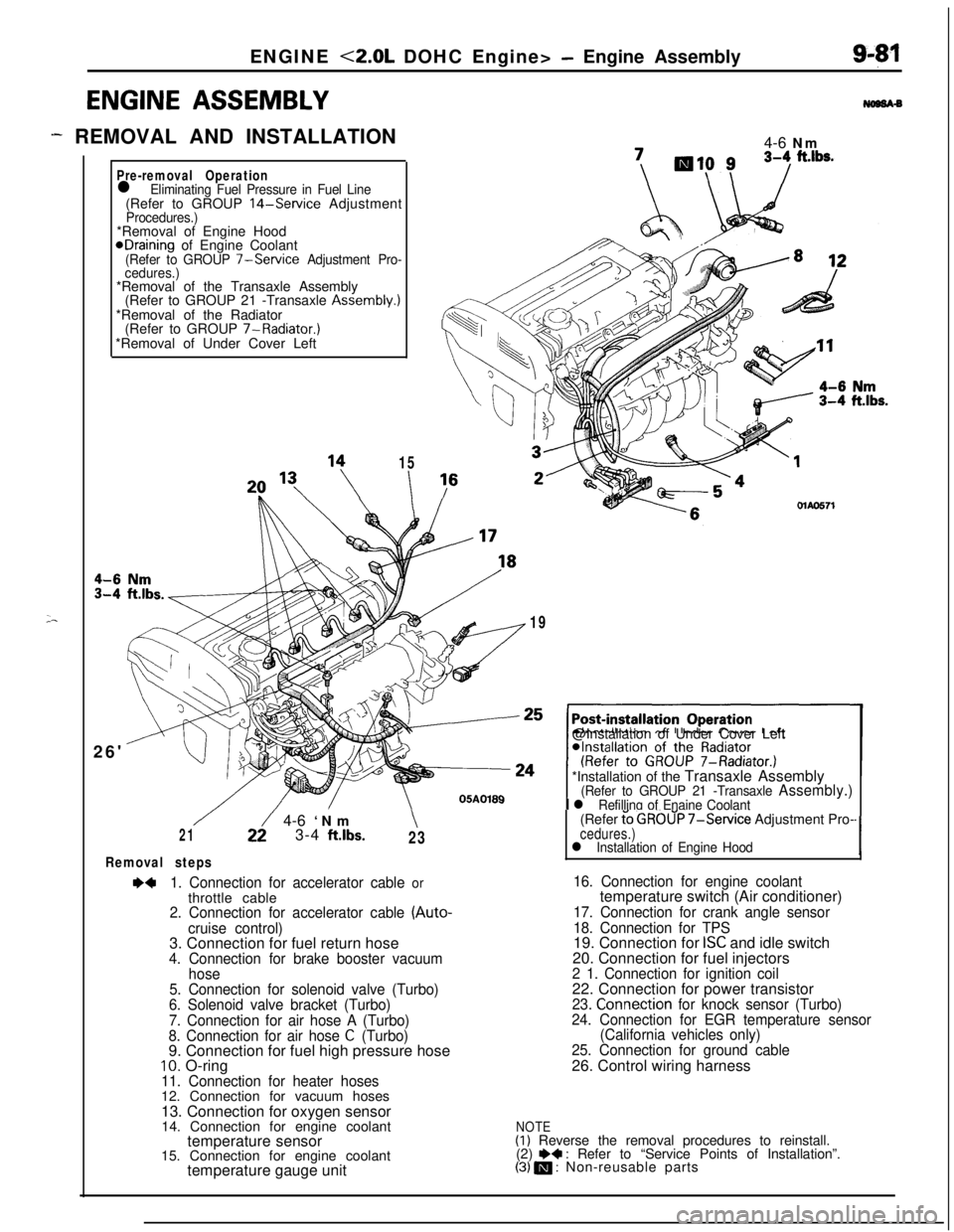
ENGINE <2.0L DOHC Engine> - Engine Assembly
ENGINE ASSEMBLY
- REMOVAL AND INSTALLATION
;-
Pre-removal Operationl Eliminating Fuel Pressure in Fuel Line(Refer to GROUP 14-Service AdjustmentProcedures.)*Removal of Engine Hood
@Draining of Engine Coolant(Refer to GROUP 7-Service Adjustment Pro-
cedures.)*Removal of the Transaxle Assembly
(Refer to GROUP 21 -Transaxle Assembly.)
*Removal of the Radiator
(Refer to GROUP 7-Radiator.)
*Removal of Under Cover Left
26'
15
I4-6 Nm\I /MAO571
19@Installation of Under Cover Left
*Installation of the Transaxle Assembly
(Refer to GROUP 21 -Transaxle Assembly.)
I l Refilling of Enaine Coolant
/22/ 4-6 ‘Nm\213-4 ftlbs.23
Removal steps
~~1. Connection for accelerator cable orthrottle cable
2. Connection for accelerator cable (Auto-
cruise control)3. Connection for fuel return hose
4. Connection for brake booster vacuum
hose
5. Connection for solenoid valve (Turbo)
6. Solenoid valve bracket (Turbo)
7. Connection for air hose A (Turbo)
8. Connection for air hose
C (Turbo)9. Connection for fuel high pressure hose
10. O-ring11. Connection for heater hoses12. Connection for vacuum hoses
13. Connection for oxygen sensor
14. Connection for engine coolant
temperature sensor
15. Connection for engine coolant
temperature gauge unit(Refer
t’o GROUP 7-Service Adjustment Pro-cedures.)l Installation of Engine Hood‘I
16. Connection for engine coolanttemperature switch (Air conditioner)
17. Connection for crank angle sensor
18. Connection for TPS19. Connection for
ISC and idle switch
20. Connection for fuel injectors
2 1. Connection for ignition coil22. Connection for power transistor
23. Connection for knock sensor (Turbo)
24. Connection for EGR temperature sensor
(California vehicles only)
25. Connection for ground cable26. Control wiring harness
NOTE(I) Reverse the removal procedures to reinstall.
(2) e+ : Refer to “Service Points of Installation”.(3) m : Non-reusable parts