lock MITSUBISHI ECLIPSE 1991 Owner's Manual
[x] Cancel search | Manufacturer: MITSUBISHI, Model Year: 1991, Model line: ECLIPSE, Model: MITSUBISHI ECLIPSE 1991Pages: 1216, PDF Size: 67.42 MB
Page 96 of 1216
2-48FRONT SUSPENSION - Centermember and CrossmemberSERVICE POINTS OF REMOVAL
22. REMOVAL OF NUT
Refer to
P.2-39.
N02YBAEa27. REMOVAL OF STABILIZER BAR
Refer to
P.2-39.34. REMOVAL OF STEERING GEAR BOX ASSEMBLY
Refer to GROUP
19-Steering Gear Box.
INSPECTIONN02YCMl
l Check the crossmember for cracks or deformation.
l Check the bushings for cracks or deterioration.
l Check the centermember for cracks or deformation.
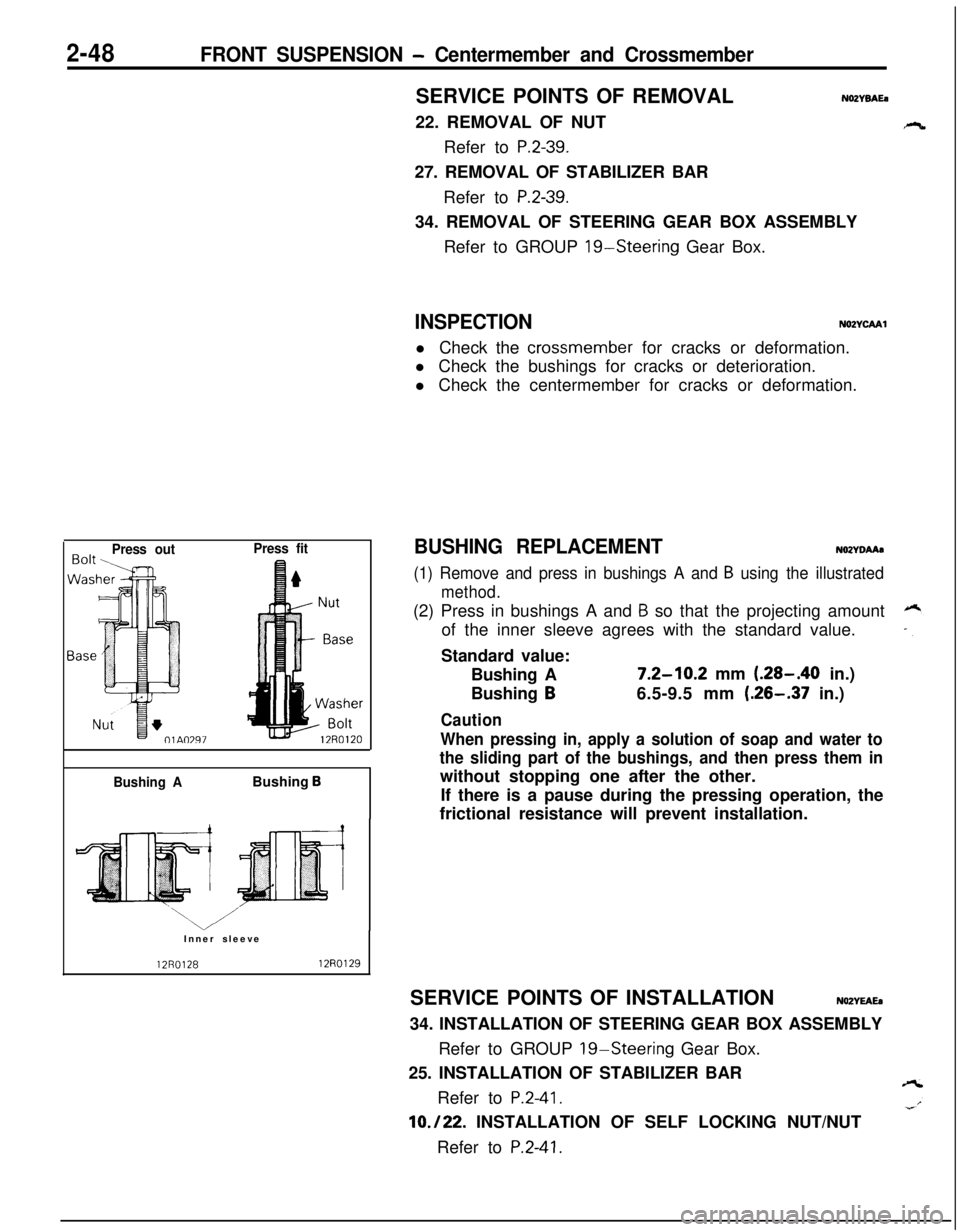
Press outPress fit
Bushing ABushing
BInner sleeve
12R012812RO129
BUSHING REPLACEMENTNOZYDAAa
(1) Remove and press in bushings A and B using the illustrated
method.(2) Press in bushings A and
B so that the projecting amount
of the inner sleeve agrees with the standard value.
Standard value:
Bushing A
7.2-10.2 mm (.28-.40 in.)
Bushing
B6.5-9.5 mm (.26-.37 in.)
Caution
When pressing in, apply a solution of soap and water to
the sliding part of the bushings, and then press them inwithout stopping one after the other.
If there is a pause during the pressing operation, the
frictional resistance will prevent installation.
SERVICE POINTS OF INSTALLATION
NOZYEAEa34. INSTALLATION OF STEERING GEAR BOX ASSEMBLY
Refer to GROUP
19-Steering Gear Box.
25. INSTALLATION OF STABILIZER BAR
Refer to
P.2-41.
10./22. INSTALLATION OF SELF LOCKING NUT/NUT
Refer to
P.2-41.
Page 98 of 1216
2-50FRONT SUSPENSION -Centermember and Crossmember
40-60 Nm
29-43 ftlbs.
“1I
30-40 Nm
22-29 ftlbs.
40-60 /Nm29-43 ftlbs.
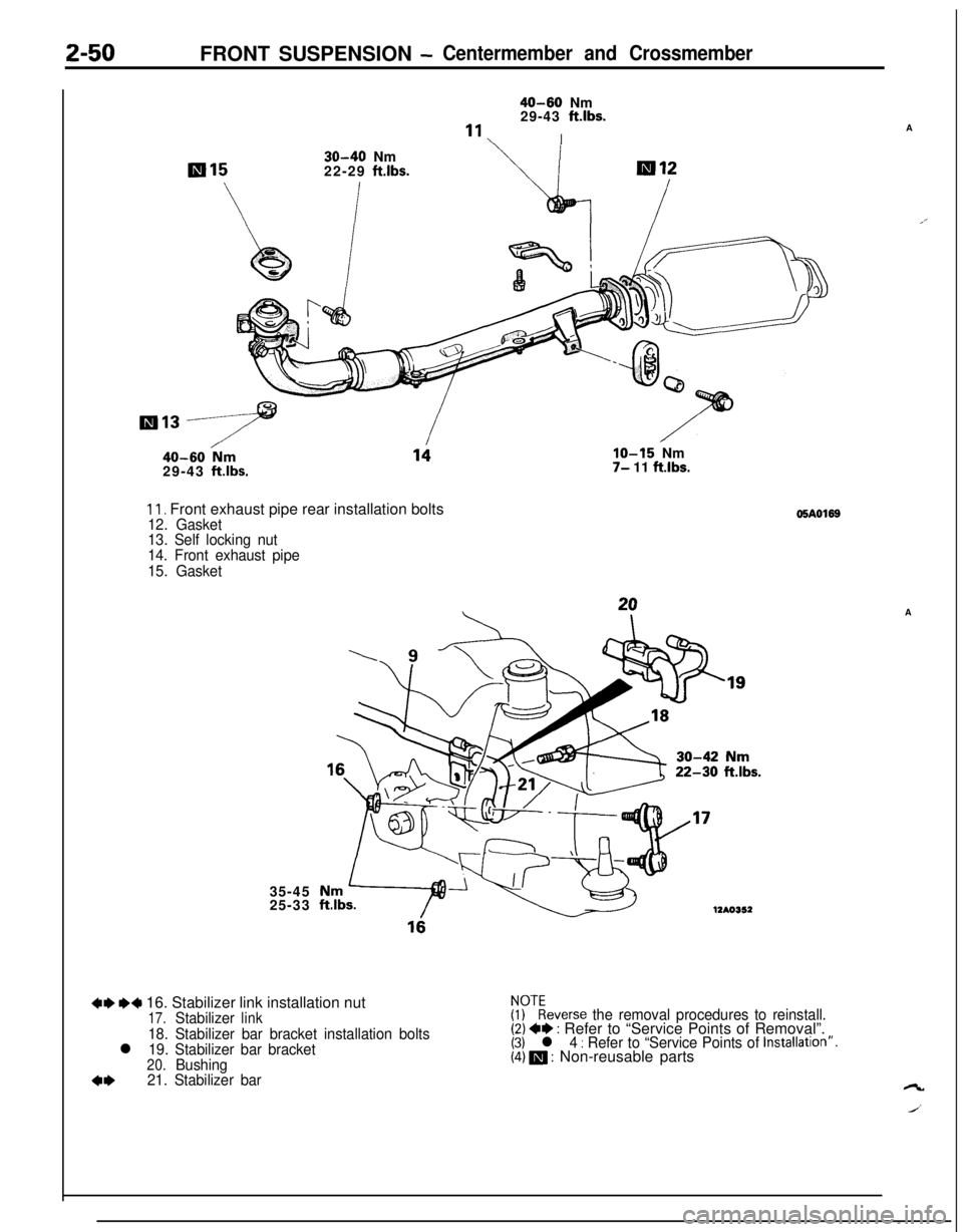
11. Front exhaust pipe rear installation bolts12. Gasket
13. Self locking nut
14. Front exhaust pipe
15. Gasket35-45
25-33
IO-15 Nm7- 11 ftlbs.
22-30 ftlbs.
12AO352
+e MI 16. Stabilizer link installation nut17.Stabilizerlink
18. Stabilizer bar bracket installation boltsl 19. Stabilizer bar bracket20.Bushing
4*21. Stabilizer bar
05AO169
$?everse the removal procedures to reinstall.(2) +* : Refer to “Service Points of Removal”.(3) l 4 : Refer to “Service Points of Installatron”.(4) m : Non-reusable partsA
A’A
ct
J’
Page 100 of 1216
FRONT SUSPENSION - Centermember and Crossmember
34
40-50 Nm
29-36 ftlbs.
38
100-12072-87 ft32
;56-72 ft.lbs.-39
-36
‘350
’ 80-100 Nm
58-72 ft.lbs.
60-100 Nm*58-72 ft.lbs.*
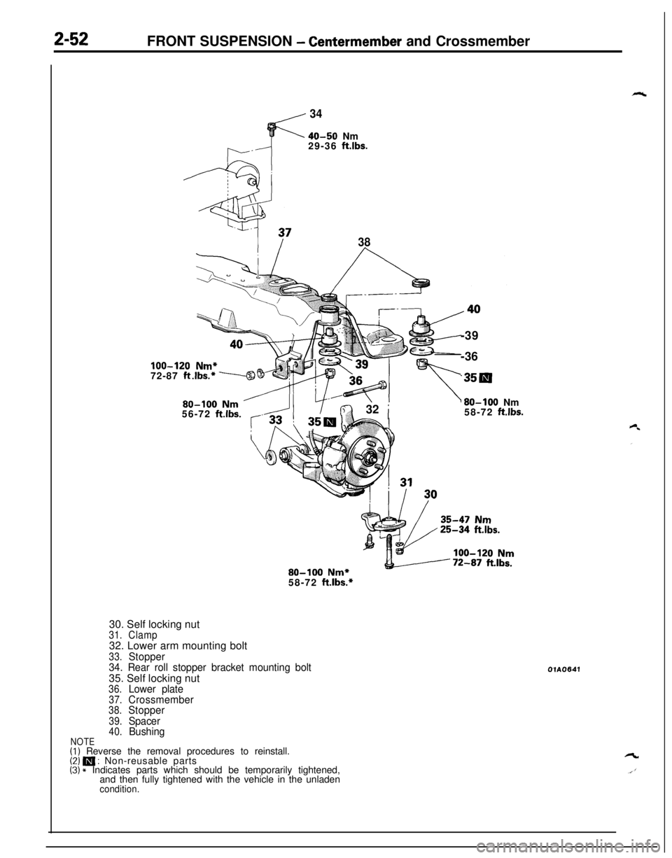
30. Self locking nut
31.Clamp32. Lower arm mounting bolt
33.Stopper
34. Rear roll stopper bracket mounting bolt35. Self locking nut
36.Lower plate37.Crossmember38.Stopper
39.Spacer40.BushingNOTE(1) Reverse the removal procedures to reinstall.(2) m : Non-reusable parts(3) * Indicates parts which should be temporarily tightened,
and then fully tightened with the vehicle in the unladen
condition.
OlA0641
Page 108 of 1216
3-6REAR AXLE - Troubleshooting
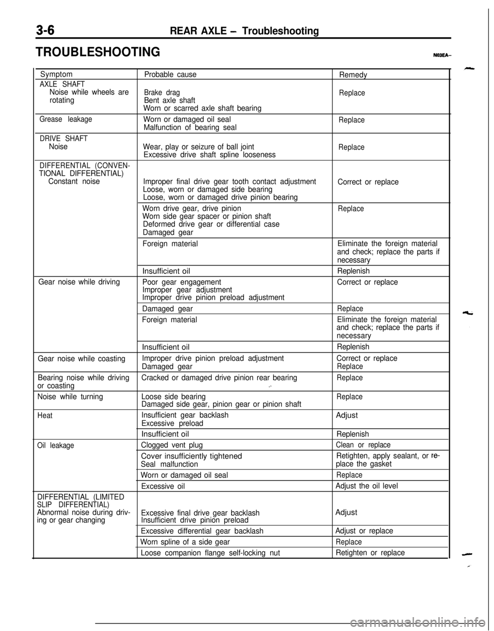
TROUBLESHOOTINGNO3EA-
Symptom
Probable cause
Remedy
AXLE SHAFTNoise while wheels areBrake drag
Replacerotating
Bent axle shaft
Worn or scarred axle shaft bearing
Grease leakageWorn or damaged oil sealReplaceMalfunction of bearing seal
DRIVE SHAFT
Noise
Wear, play or seizure of ball jointReplaceExcessive drive shaft spline looseness
DIFFERENTIAL (CONVEN-TIONAL DIFFERENTIAL)
Constant noise
Improper final drive gear tooth contact adjustment
Correct or replace
Loose, worn or damaged side bearing
Loose, worn or damaged drive pinion bearing
Worn drive gear, drive pinion
ReplaceWorn side gear spacer or pinion shaft
Deformed drive gear or differential case
Damaged gear
Foreign materialEliminate the foreign material
and check; replace the parts if
necessaryInsufficient oil
Replenish
Gear noise while driving
Poor gear engagementCorrect or replace
Improper gear adjustment
Improper drive pinion preload adjustment
Damaged gear
Replace
Foreign materialEliminate the foreign material
and check; replace the parts if
necessaryInsufficient oil
Replenish
Gear noise while coastingImproper drive pinion preload adjustmentCorrect or replace
Damaged gear
Replace
Bearing noise while drivingCracked or damaged drive pinion rear bearingReplace
or coasting.-
Noise while turningLoose side bearingReplaceDamaged side gear, pinion gear or pinion shaft
HeatInsufficient gear backlashAdjust
Excessive preloadInsufficient oil
Replenish
Oil leakageClogged vent plugClean or replaceCover insufficiently tightened
Retighten, apply sealant, or re-
Seal malfunctionplace the gasket
Worn or damaged oil seal
Replace
Excessive oilAdjust the oil level
DIFFERENTIAL (LIMITED
SLIP DIFFERENTIAL)Abnormal noise during driv-
Excessive final drive gear backlashAdjusting or gear changingInsufficient drive pinion preload
Excessive differential gear backlashAdjust or replace
Worn spline of a side gear
Replace
Loose companion flange self-locking nutRetighten or replace
Page 109 of 1216
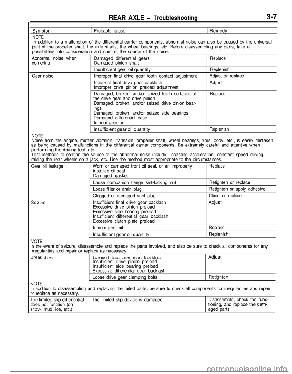
REAR AXLE - Troubleshooting3-7
Symptom
NOTE
1 Probable cause1 Remedy
In addition to a malfunction of the differential carrier components, abnormal noise can also be caused by the universal
joint of the propeller shaft, the axle shafts, the wheel bearings, etc. Before disassembling any parts, take all
possibilities into consideration and confirm the source of the noise.
Abnormal noise when
Damaged differential gears
ReplacecorneringDamaged pinion shaftInsufficient gear oil quantity
Replenish
Gear noiseImproper final drive gear tooth contact adjustmentAdjust or replace
Incorrect final drive gear backlashAdjust
Improper drive pinion preload adjustment
Damaged, broken, and/or seized tooth surfaces of
Replacethe drive gear and drive pinion
Damaged, broken, and/or seized drive pinion bear-
ings
NOTE
Damaged, broken, and/or seized side bearings
Damaged differential case
Inferior gear oilInsufficient gear oil quantity
Replenish
Noise from the engine, muffler vibration, transaxle, propeller shaft, wheel bearings, tires, body, etc., is easily mistaken
as being caused by malfunctions in the differential carrier components. Be extremely careful and attentive whenperforming the driving test, etc.
Test methods to confirm the source of the abnormal noise include:coasting acceleration, constant speed driving,
raising the rear wheels on a jack, etc. Use the method most appropriate to the circumstances.
Gear oil leakageWorn or damaged front oil seal, or an improperlyReplace
installed oil seal
Damaged gasket
Seizure
VOTE
Loose companion flange self-locking nut
Loose filler or drain plug
Clogged or damaged vent plug
Insufficient final drive gear backlash
Excessive drive pinion preload
Excessive side bearing preload
Insufficient differential gear backlash
Excessive clutch plate preload
Inferior gear oilInsufficient gear oil quantityRetighten or replace
Retighten or apply adhesive
Clean or replaceAdjust
Replace
Replenish
n the event of seizure, disassemble and replace the parts involved, and also be sure to check all components for any
rregularities and repair or replace as necessary.
3reak downIncorrect final drive gear backlashAdjustInsufficient drive pinion preload
Insufficient side bearing preload
Excessive differential gear backlash
Loose drive gear clamping boltsRetighten
VOTEn addition to disassembling and replacing the failed parts, be sure to check all components for irregularities and repairIr
replace as necessary.
The limited slip differentialThe limited slip device is damagedDisassemble, check the func-
lees not function (ontioning, and replace the dam-
;now, mud, ice, etc.)aged parts
Page 110 of 1216
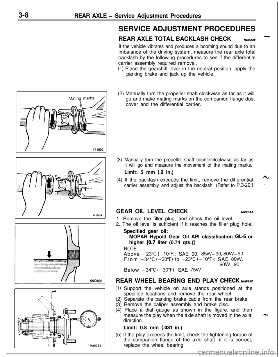
3-8REAR AXLE - Service Adjustment Procedures
09D031
llA0065SERVICE ADJUSTMENT PROCEDURES
REAR AXLE TOTAL BACKLASH CHECK
N03FAAF
If the vehicle vibrates and produces a booming sound due to animbalance of the driving system, measure the rear axle total
backlash by the following procedures to see if the differential
carrier assembly required removal.
(1) Place the gearshift lever in the neutral position, apply the
parking brake and jack up the vehicle.
(2) Manually turn the propeller shaft clockwise as far as it will
go and make mating marks on the companion flange dust
cover and the differential carrier.
(3) Manually turn the propeller shaft counterclockwise as far as
it will go and measure the movement of the mating marks.Limit: 5 mm
(.2 in.)
(4) If the backlash exceeds the limit, remove the differential
carrier assembly and adjust the backlash. (Refer to P.3-20.)
GEAR OIL LEVEL CHECKN03FCAA1. Remove the filler plug, and check the oil level.
2. The oil level is sufficient if it reaches the filler plug hole.
Specified gear oil:
MOPAR Hypoid Gear Oil API classification
GL-5 or
higher
[0.7 liter (0.74 qts.)]
NOTEAbove
-23°C (-10°F): SAE 90, 85W-90, 8OW-90
From
-34°C (-30°F) to -23°C (-10°F): SAE 8OW,
8OW-90Below
-34°C (-30°F): SAE 75WREAR WHEEL BEARING END PLAY
CHECKN03FEAE
(1) Support the vehicle on axle stands positioned at the
specified locations and remove the rear wheel.
(2) Separate the parking brake cable from the rear brake.
(3) Remove the caliper assembly and brake disc.
(4) Place a dial gauge as shown in the figure, and then
measure the play when the axle shaft is moved in the axial
direction.Limit: 0.8 mm
(.031 in.)
(5) If the play exceeds the limit, check the tightening torque of
the companion flange of the axle shaft; if it is correct,
replace the wheel bearing.
Page 111 of 1216
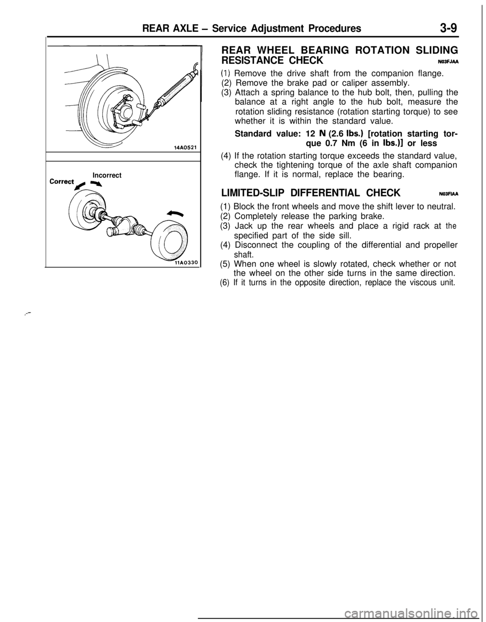
REAR AXLE - Service Adjustment Procedures3-9
14A0521
IncorrectREAR WHEEL BEARING ROTATION SLIDING
RESISTANCE CHECKNOOFJAA
(1) Remove the drive shaft from the companion flange.
(2) Remove the brake pad or caliper assembly.
(3) Attach a spring balance to the hub bolt, then, pulling the
balance at a right angle to the hub bolt, measure the
rotation sliding resistance (rotation starting torque) to see
whether it is within the standard value.
Standard value: 12
N (2.6 Ibs.) [rotation starting tor-
que 0.7 Nm (6 in
Ibs.)] or less
(4) If the rotation starting torque exceeds the standard value,
check the tightening torque of the axle shaft companion
flange. If it is normal, replace the bearing.
LIMITED-SLIP DIFFERENTIAL CHECKNOJFIAA(1) Block the front wheels and move the shift lever to neutral.
(2) Completely release the parking brake.
(3) Jack up the rear wheels and place a rigid rack at the
specified part of the side sill.
(4) Disconnect the coupling of the differential and propeller
shaft.(5) When one wheel is slowly rotated, check whether or not
the wheel on the other side turns in the same direction.
(6) If it turns in the opposite direction, replace the viscous unit.
_--
Page 112 of 1216
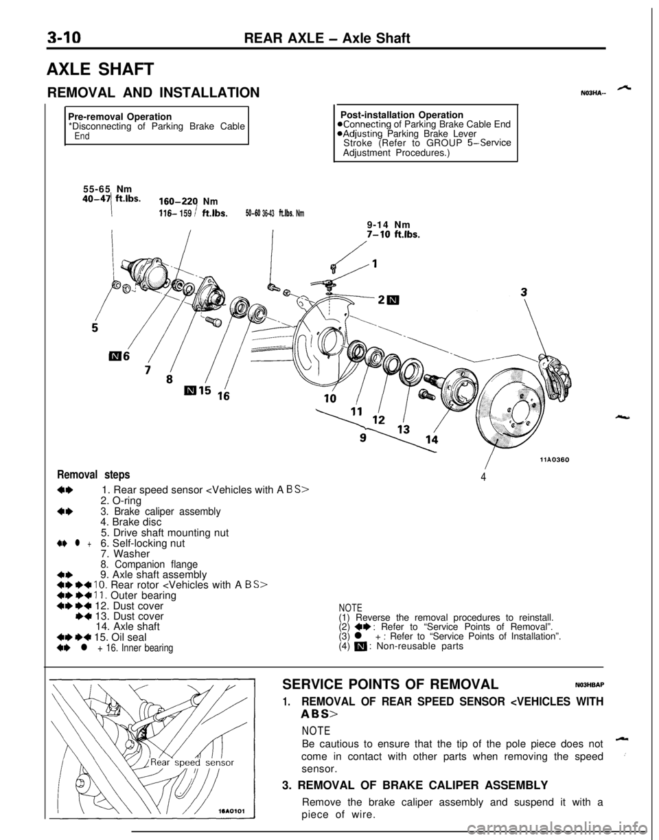
3-10REAR AXLE - Axle Shaft
AXLE SHAFT
REMOVAL AND INSTALLATION
Pre-removal Operation
*Disconnecting of Parking Brake Cable
End9-14 Nm
7-W ft.lbs.55-65Nm
40-47ft.lbs.160-220Nm
!116- 159 Ift.lbs.50-60 36-43ft.lbs. Nm
Removal steps
4*1. Rear speed sensor
c*3. Brake caliper assembly4. Brake disc
/llA03604
5. Drive shaft mounting nut
+e l +6. Self-locking nut
7. Washer
8. Companion flange
c+9. Axle shaft assembly4I) +4 10. Rear rotor
14. Axle shaft
4* +4 15. Oil seal+e l + 16. Inner bearing
NOTE(1) Reverse the removal procedures to reinstall.
(2)
*I) : Refer to “Service Points of Removal”.
(3) l + : Refer to “Service Points of Installation”.
(4) m : Non-reusable parts
ALNOBHA-Post-installation Operation
Konnecting of Parking Brake Cable EndaAdjusting Parking Brake Lever
Stroke (Refer to GROUP
5-ServiceAdjustment Procedures.)
SERVICE POINTS OF REMOVAL
NOBHBAP
1.REMOVAL OF REAR SPEED SENSOR
Be cautious to ensure that the tip of the pole piece does not
Acome in contact with other parts when removing the speed
csensor.
3. REMOVAL OF BRAKE CALIPER ASSEMBLY
Remove the brake caliper assembly and suspend it with a
piece of wire.
Page 113 of 1216
12A0611
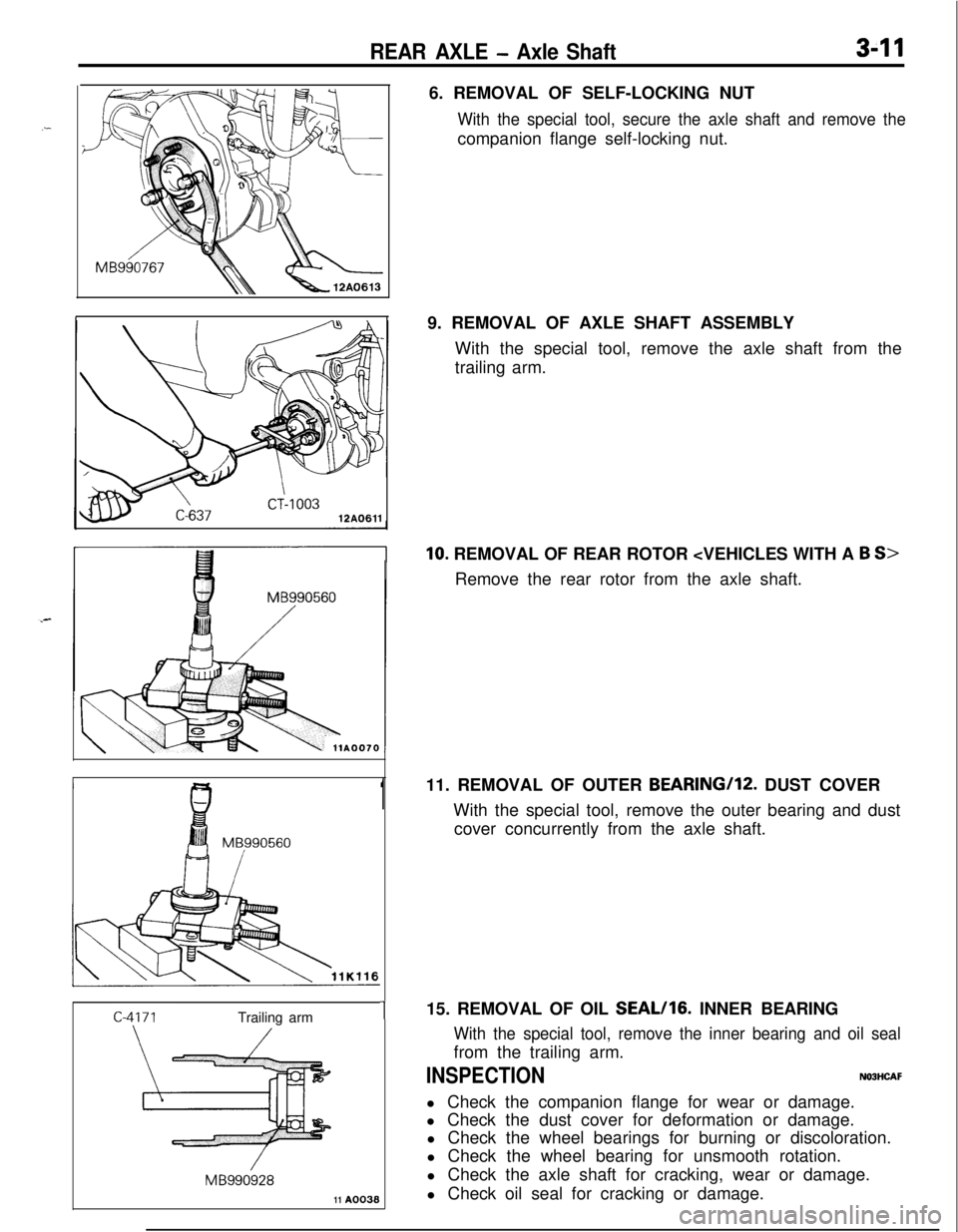
REAR AXLE - Axle Shaft3-116. REMOVAL OF SELF-LOCKING NUT
With the special tool, secure the axle shaft and remove thecompanion flange self-locking nut.
9. REMOVAL OF AXLE SHAFT ASSEMBLY
With the special tool, remove the axle shaft from the
trailing arm.
10. REMOVAL OF REAR ROTOR
111. REMOVAL OF OUTER BEARING/lZ. DUST COVER
With the special tool, remove the outer bearing and dust
cover concurrently from the axle shaft.
115. REMOVAL OF OIL SEAL/lG. INNER BEARING
MB990560
/Trailing arm
/
/MB99092811
A0038
With the special tool, remove the inner bearing and oil sealfrom the trailing arm.
INSPECTIONNOBHCAFl Check the companion flange for wear or damage.
l Check the dust cover for deformation or damage.
l Check the wheel bearings for burning or discoloration.
l Check the wheel bearing for unsmooth rotation.
l Check the axle shaft for cracking, wear or damage.
l Check oil seal for cracking or damage.
Page 115 of 1216
REAR AXLE - Axle Shaft/Drive Shaft3-13
DRIVE SHAFTN03JA--
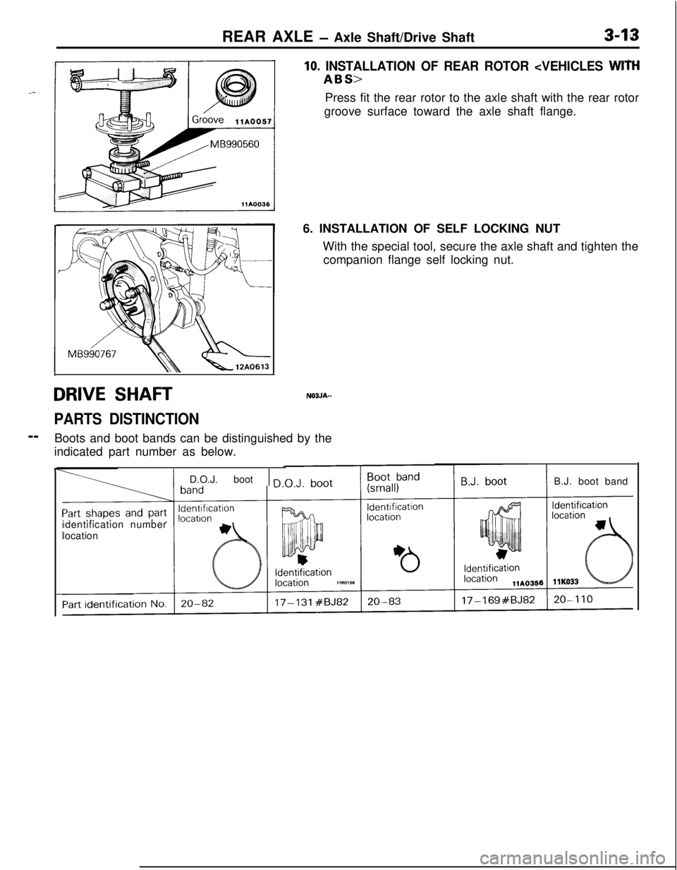
PARTS DISTINCTION--
Boots and boot bands can be distinguished by the
indicated part number as below.
10. INSTALLATION OF REAR ROTOR
groove surface toward the axle shaft flange.
6. INSTALLATION OF SELF LOCKING NUT
With the special tool, secure the axle shaft and tighten the
companion flange self locking nut.
F
I
IIidentification number
location
1 D.O.J. boot 1 nB.J. boot band