eco mode switch MITSUBISHI ECLIPSE CROSS 2020 (in English) Owner's Guide
[x] Cancel search | Manufacturer: MITSUBISHI, Model Year: 2020, Model line: ECLIPSE CROSS, Model: MITSUBISHI ECLIPSE CROSS 2020Pages: 427, PDF Size: 78.05 MB
Page 124 of 427
Power window control
Features and controls 5-43
5
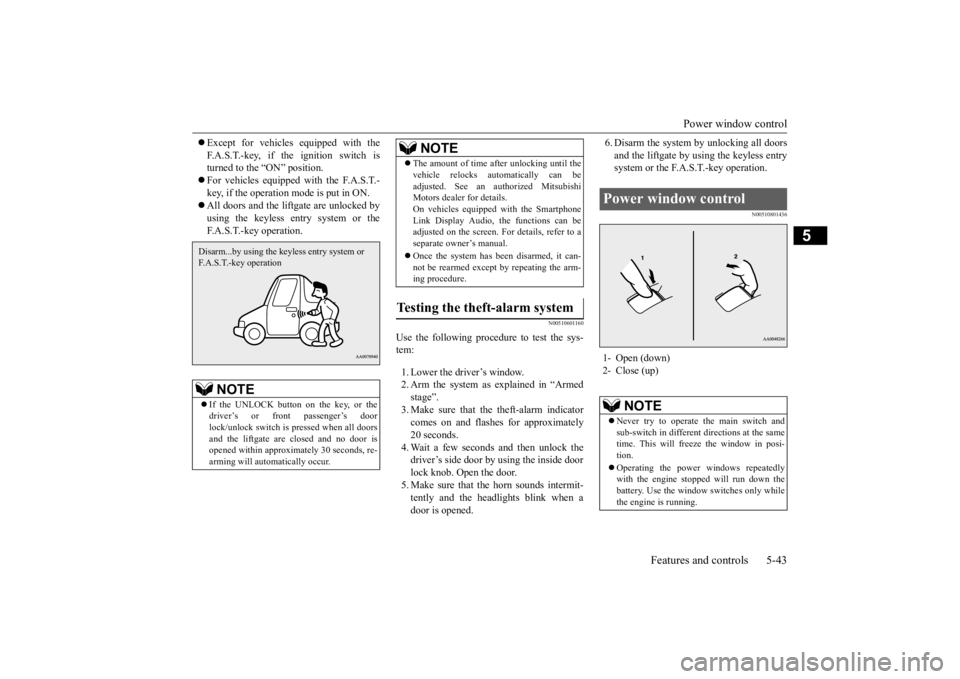
Except for vehicles equipped with the F.A.S.T.-key, if the ignition switch is turned to the “ON” position. For vehicles equipped with the F.A.S.T.- key, if the operation mode is put in ON. All doors and the liftgate are unlocked by using the keyless entry system or theF.A.S.T.-key operation.
N00510601160
Use the following procedure to test the sys- tem: 1. Lower the driver’s window. 2. Arm the system as explained in “Armedstage”. 3. Make sure that the theft-alarm indicator comes on and flashes for approximately20 seconds. 4. Wait a few seconds and then unlock the driver’s side door by using the inside doorlock knob. Open the door. 5. Make sure that the horn sounds intermit- tently and the headlights blink when adoor is opened.
6. Disarm the system by unlocking all doors and the liftgate by using the keyless entry system or the F.A.S.T.-key operation.
N00510801436
NOTE
If the UNLOCK button on the key, or the driver’s or front passenger’s doorlock/unlock switch is pressed when all doors and the liftgate are closed and no door is opened within approximately 30 seconds, re-arming will automatically occur.Disarm...by using the keyless entry system or F.A.S.T.-key operation
The amount of time after unlocking until the vehicle relocks automatically can be adjusted. See an authorized Mitsubishi Motors dealer for details. On vehicles equipped with the SmartphoneLink Display Audio, the functions can be adjusted on the screen. For details, refer to a separate owner’s manual. Once the system has been disarmed, it can- not be rearmed except by repeating the arm-ing procedure.
Testing the theft-alarm system
NOTE
Power window control 1- Open (down) 2- Close (up)
NOTE
Never try to operate the main switch and sub-switch in different directions at the same time. This will freeze the window in posi- tion. Operating the power windows repeatedly with the engine stopped will run down thebattery. Use the window switches only while the engine is running.
BK0277700US.bo
ok 43 ページ 2019年3月8日 金曜日 午前9時23分
Page 125 of 427
Power window control 5-44 Features and controls
5
N00548701182
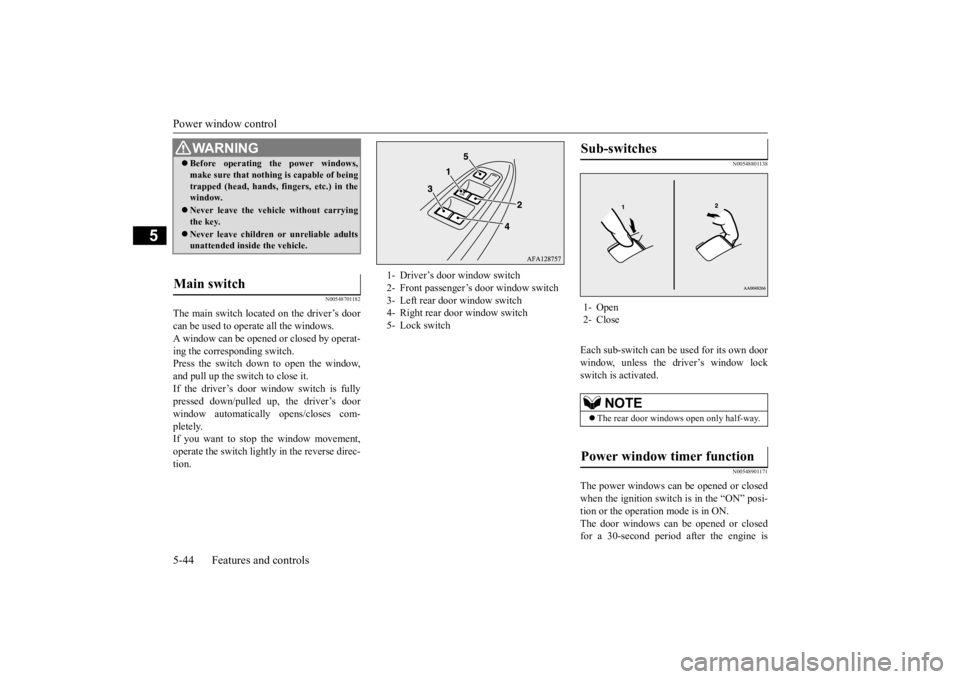
The main switch located on the driver’s door can be used to operate all the windows. A window can be opened or closed by operat-ing the corresponding switch. Press the switch down to open the window, and pull up the switch to close it.If the driver’s door window switch is fully pressed down/pulled up, the driver’s door window automatically opens/closes com-pletely. If you want to stop the window movement, operate the switch lightly in the reverse direc-tion.
N00548801138
Each sub-switch can be used for its own door window, unless the driver’s window lock switch is activated.
N00548901171
The power windows can be opened or closed when the ignition switch is in the “ON” posi- tion or the operation mode is in ON.The door windows can be opened or closed for a 30-second period after the engine is
WA R N I N G Before operating the power windows, make sure that nothing is capable of being trapped (head, hands, fingers, etc.) in the window. Never leave the vehicle without carrying the key. Never leave children or unreliable adults unattended inside the vehicle.
Main switch
1- Driver’s door window switch 2- Front passenger’s door window switch 3- Left rear door window switch 4- Right rear door window switch5- Lock switch
Sub-switches 1- Open 2- Close
NOTE
The rear door windows open only half-way.
Power window timer function
BK0277700US.bo
ok 44 ページ 2019年3月8日 金曜日 午前9時23分
Page 126 of 427
Power window control
Features and controls 5-45
5
stopped. However, once the driver’s door or the front passenger’s door is opened, the power windows cannot be operated.
N00549001182
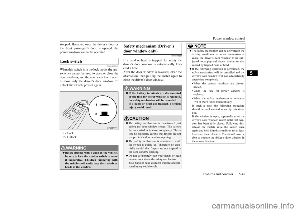
When this switch is in the lock mode, the sub-switches cannot be used to open or close the door windows, and the main switch will openor close only the driver’s door window. Tounlock the switch, press it again.
N00528801217
If a hand or head is trapped, for safety thedriver’s door window is automatically low- ered a little. After the door window is lowered, clear theobstruction, then pull up the switch again to close the driver’s door window.
Lock switch 1- Lock2- UnlockWA R N I N G Before driving with a child in the vehicle, be sure to lock the window switch to make it inoperative. Children tampering withthe switch could easily trap their hands or heads in the window.
Safety mechanism (Driver’s door window only)
WA R N I N G If the battery terminals are disconnected or the fuse for power window is replaced, the safety mechanism will be cancelled. If a hand or head got trapped, a seriousinjury could result.CAUTION The safety mechanism is deactivated just before the door window closes. This allowsthe door window to close completely. There- fore be especially careful that fingers are not trapped in the door window opening. The safety mechanism is deactivated while the switch is pulled up. Therefore be espe- cially careful that fingers are not trapped in the door window opening. Do not deliberately trap your hands or head in order to activate the safety mechanism.Your hand or head could be trapped and per- sonal injury could result.
NOTE
The safety mechanism can be activated if the driving conditions or other circumstances cause the driver’s door window to be sub- jected to a physical shock similar to that caused by trapped hand or head. If the following operation is performed, the safety mechanism will be cancelled and thedriver’s door window will not automatically open/close completely. • When the battery terminals are discon- nected. • When the fuse for power window is replaced. • When the safety mechanism is activated five or more times consecutively. In such a case, the following procedure should be implemented to rectify this situa- tion.If the window is open, repeatedly raise the driver’s door window switch until that win- dow has been fully closed. Following this,release the switch, raise the switch once again and hold it in this condition for at least 1 second, then release it. You should now beable to operate the driver’s door window in the normal fashion.
BK0277700US.bo
ok 45 ページ 2019年3月8日 金曜日 午前9時23分
Page 127 of 427
Power panoramic sunroof (if so equipped) 5-46 Features and controls
5
N00551400043
Wind buffeting can be described as the per- ception of pressure on the ears or a booming or rumbling sound. Your vehicle may exhibit wind buffeting when driving with one or bothrear door windows down or partially opened. This is a normal occurrence that can be mini- mized. If the buffeting occurs with the reardoor windows open, open the front door win-dows as well as the rear door windows to minimize the condition.
N00594700036
The front sunroof & front shade can be opened or closed with the ignition switch in the “ON” position or the operation mode in ON.
What to do if you hear wind buffeting when driving Power panoramic sunroof
(if
so equipped)
WA R N I N G Do not put head, hands or anything else out of the front sunroof opening whiledriving the vehicle. Never leave children or unreliable adults unattended inside the vehicle. Never leave the vehicle without carrying the key. Before operating the front sunroof, front shade, or rear shade, make sure that noth- ing is capable of being trapped (head,hands, fingers, etc.) in the front sunroof, front shade, or rear shade.
Because the front sunroof opens to the outside of the vehicle, do not open the sun- roof when cleaning the top of the roof, etc. Your hands or arms could be trapped.NOTE
When leaving the vehicle unattended, be sure to close the front sunroof and carry thekey. Do not try to operate the front sunroof if it is frozen closed (after snow fall or during extreme cold). Do not sit or place heavy luggage on the front sunroof or roof opening edge. Do not apply any force that may cause dam- age to the sunroof. Release the switch when the front sunroof, front shade, or rear shade starts to move. If the front sunroof, front shade, or rear shade does not operate when the switch is operated, release the switch and checkwhether something is trapped by the sunroof or shade. If nothing is trapped, we recom- mend you to have the sunroof or shade checked at an authorized Mitsubishi Motors dealer. Be careful when tilting up the front sunroof if a ski carrier or a ro
of carrier is installed.
Depending on the model of ski carrier or roof carrier, the front sunroof may contact the car- rier when the front sunroof is tilted up.WA R N I N G
Be sure to close the front sunroof completely when washing the vehicle or when leaving the vehicle. After washing the vehicle or after rain be sure to wipe off any water that is on the front sunroof before operating it. Operating the front sunroof, front shade, or rear shade repeatedly with the engine turned off will run down the battery. Operate thefront sunroof, front shade, and rear shade only while the engine is running.
Front sunroof & front shade
NOTE
BK0277700US.bo
ok 46 ページ 2019年3月8日 金曜日 午前9時23分
Page 129 of 427
Power panoramic sunroof (if so equipped) 5-48 Features and controls
5
To stop the shade before it is fully closed, operate the switches in any of the directions (1) to (6). Within approximately 30 seconds after the ignition switch is changed to “ACC” or“OFF” or the operatio
n mode is changed to
ACC or OFF, the front sunroof and front shade can be opened and closed.However, if the driver’s or front passenger’s door is opened within 30 seconds after the ignition switch is changed to “ACC” or“OFF” or the operatio
n mode is changed to
ACC or OFF, the front sunroof and front shade cannot be opened or closed. If a person’s hand, neck, etc., is trapped in the front sunroof or front sh
ade, the front sunroof
or front shade will au
tomatically open a max-
imum of 8 inches (20 cm) as a safety func- tion. After the front sunroof and front shadeopen, you can use the switch to close them.
If the safety mechanism operates five times or more consecutively, you will not be able to close the front sunroof and front shade nor- mally.If this occurs, perform the following proce- dure to reset the safety mechanism. 1. Press and hold the switch in direction (3) or pull and hold the switch in direction(4). 2. The front sunroof (if open) and front shade will move to the fully closed posi-tions in small increments. 3. When the front sunroof and front shade have both stopped in the fully closed posi- tions, release the switch. (The resetting procedure is finished.)
If the front sunroof and front shade do not move correctly to the fully closed positions after you perform the resetting procedure, contact an authorized Mitsubishi Motorsdealer.
The rear shade can be opened or closed with the ignition switch in the “ON” position or the operation mode in ON.
NOTE
If the front sunroof is open, it will close together with the front shade.
Timer function
Safety mechanism
NOTE
If the front sunroof and front shade are both open, the front sunroof will move to the fullyclosed position, and then the front shade will move to the fully closed position.
CAUTION The safety mechanism is cancelled just before the front sunroof and front shade are fully closed. This allows the front sunroof and front shade to close completely. There- fore be especially careful that no fingers aretrapped in the front s
unroof and front shade.
NOTE
The safety mechanism can be activated if the driving conditions or other circumstancescause the front sunroof or the front shade to be subjected to a physical shock similar to that caused by a trapped hand or head. Do not release the switch until the resetting procedure is finished. If you release theswitch, the resetting mode will be cancelled. To perform the resetting procedure again, repeat the procedure from step 1.
Rear shade
BK0277700US.bo
ok 48 ページ 2019年3月8日 金曜日 午前9時23分
Page 132 of 427
Parking brake
Features and controls 5-51
5
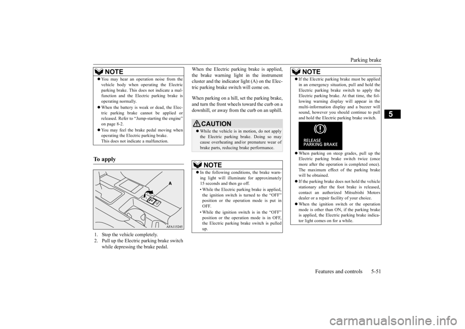
When the Electric parking brake is applied, the brake warning light in the instrument cluster and the indicator light (A) on the Elec- tric parking brake switch will come on. When parking on a hill, set the parking brake, and turn the front wheels toward the curb on a downhill, or away from the curb on an uphill.
NOTE
You may hear an operation noise from the vehicle body when operating the Electric parking brake. This
does not indicate a mal-
function and the Electric parking brake is operating normally. When the battery is weak or dead, the Elec- tric parking brake cannot be applied orreleased. Refer to “Jump-starting the engine” on page 8-2. You may feel the brake pedal moving when operating the Electric parking brake. This does not indicate a malfunction.
To apply
1. Stop the vehicle completely. 2. Pull up the Electric parking brake switch
while depressing the brake pedal.
CAUTION While the vehicle is in motion, do not apply the Electric parking brake. Doing so may cause overheating and/or premature wear of brake parts, reducing brake performance. NOTE
In the following conditions, the brake warn- ing light will illuminate for approximately 15 seconds and then go off. • While the Electric parking brake is applied, the ignition switch is turned to the “OFF”position or the operation mode is put in OFF. • While the ignition switch is in the “OFF” position or the operation mode is in OFF, the Electric parking brake switch is pulled up.
If the Electric parking brake must be applied in an emergency situation, pull and hold the Electric parking brake switch to apply the Electric parking brake. At that time, the fol- lowing warning display will appear in themulti-information display and a buzzer will sound, however you should continue to pull and hold the Electric parking brake switch. When parking on steep grades, pull up the Electric parking brake switch twice (once more after the operation is completed once).The maximum effect of the parking brake will be obtained. If the parking brake does
not hold the vehicle
stationary after the foot brake is released, contact an authorized Mitsubishi Motorsdealer or a repair facility of your choice. When the ignition switch or the operation mode is other than ON, if the parking brake is applied, the Electric parking brake indica- tor light comes on for a while.NOTE
BK0277700US.bo
ok 51 ページ 2019年3月8日 金曜日 午前9時23分
Page 134 of 427

Steering wheel height and reach adjustment
Features and controls 5-53
5
Warning light Warning display If there is a malfunction in the system, the warning light will come on. In addition, thewarning display appears on the information screen in the multi-information display.
Under normal conditions, the warning light only comes on when the ignition switch is turned to the “ON” position or the operation mode is put in ON and goes off a few secondslater.
N00511501241
To adjust the steering wheel to the desiredposition, move the lever upward or down-
If the acceleration of the vehicle seems abnormally slow after the vehicle has been parked with the Electric parking brake applied in cold weather, stop the vehicle in a safe place, then apply and release the Elec-tric parking brake. If the vehicle acceleration is still slow, contact the nearest authorized Mitsubishi Motors dealer or a repair facilityof your choice.NOTE
When the ignition switch or the operation mode is other than ON, the parking brake cannot be released. If the Electric parking brake does not auto- matically release, it may be released by man-ual operation. When the selector lever is other than “P” (PARK) position, if you try to release the Electric parking brake without depressing the brake pedal, the warning display willappear.CAUTION
If you start driving without releasing the Electric parking brake, the warning display will appear. If the driver’s foot contacts the accelerator pedal in the condition that the Electric park-ing brake can release by an automatic opera- tion, the Electric parking brake may be released automatically.
Warning light/display
NOTE
CAUTION When the Electric parking brake warning light does not illuminate or remains illumi- nated when the ignition switch is turned tothe “ON” position or the operation mode is put in ON, or comes on while driving, the Electric parking brake may not be applied orreleased. Immediately contact the nearest authorized Mitsubishi Motors dealer or a repair facilityof your choice. For details, refer to “Electric parking brake warning light” on page 5-184. When parking your vehicle while the Elec-tric parking brake warning light is illumi- nated, park the vehicle on level and stable ground, move the selector lever to the “P”(PARK) position and place chocks, blocks, stones behind and in front of the tires to pre- vent the vehicle from moving.
Steering wheel height and reach adjustment
BK0277700US.bo
ok 53 ページ 2019年3月8日 金曜日 午前9時23分
Page 138 of 427
Outside rearview mirrors
Features and controls 5-57
5
N00549101196
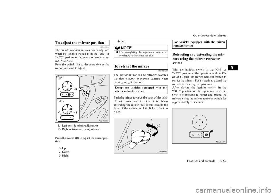
The outside rearview mirrors can be adjusted when the ignition switch is in the “ON” or“ACC” position or the operation mode is put in ON or ACC. Push the switch (A) to the same side as themirror you wish to adjust. Press the switch (B) to adjust the mirror posi- tion.
N00549201269
The outside mirror can be retracted towards the side window to prevent damage whenparking in tight locations. Push the mirror towards the back of the vehi- cle with your hand to retract it in. Whenextending the mirror, pull it out towards the front of the vehicle until it clicks to lock in place.
With the ignition switch in the “ON” or “ACC” position or the
operation mode in ON
or ACC, push the mirror retractor switch toretract the mirrors. Push it again to extend themirrors to their original positions. After placing the ignition switch in the “OFF” position or the operation mode inOFF, it is possible to retract and extend the mirrors using the mirror retractor switch for approximately 30 seconds.
To adjust the mirror position L- Left outside mirror adjustment R- Right outside mirror adjustment 1- Up 2- Down 3- RightType 1 Type 2
4- Left
NOTE
After completing the adjustment, return the switch (A) to the center position.
To retract the mirror Except for vehicles equipped with the mirror retractor switch
For vehicles equipped with the mirrorretractor switchRetracting and extending the mir- rors using the mirror retractor switch
BK0277700US.bo
ok 57 ページ 2019年3月8日 金曜日 午前9時23分
Page 143 of 427
Starting the engine 5-62 Features and controls
5
This model is equipped with an electronically controlled fuel injection system. This is a sys- tem that automatically controls fuel injection.There is usually no need to depress the accel- erator pedal when starting the engine. The starter should not be run for more than15 seconds at a time. To prevent battery drain, wait a few seconds between attempts to restart the engine. 1. Make sure all occupants are properly seated with seat belts fastened.
2. Insert the ignition key. 3. Press and hold the brake pedal down firmly with your right foot. 4. Make sure the selector lever is in the “P”(PARK) position. 5. Turn the ignition switch to the “ON” posi- tion and make certain that all warninglights are functioning properly before starting the engine. 6. Turn the ignition switch to the “START”position without pressing the acceleratorpedal. Release the ignition switch when the engine starts.
After several attempts, you may experience that the engine still does not start. 1. Make sure that all electric devices, such as lights, air conditioning blower and rearwindow defogger, are turned off.
2. While depressing the brake pedal, press the accelerator pedal halfway and hold it there, then crank the engine. Release the accelerator pedal, immediately after theengine starts. 3. If the engine still will not start, the engine could be flooded with too much gasoline.While depressing the brake pedal, push the accelerator pedal all the way down and hold it there, then crank the engine for5 to 6 seconds. Return the ignition switchto the “OFF” and release the accelerator pedal. Wait a few seconds, and then crank the engine again for 5 to 6 seconds whiledepressing the brake pedal, but do not push the accelerator pedal. Release the ignition switch if the engine starts. If theengine fails to start, repeat these proce- dures. If the engine st
ill will not start, con-
tact your local Mitsubishi Motors dealeror a repair facility of your choice for assistance.
When the ambient temperature is -22 °F (-30 °C) or lower, it may not be possible tostart from a standstill even with the selector
WA R N I N G Never run the engine in a closed or poorly ventilated area any longer than is needed to move your vehicle out of the area. Car- bon monoxide gas, which is odorless and extremely poisonous, could build up andcause serious injury or death.CAUTION Do not push-start the vehicle.Do not run the engine at high revolutions or drive at high speeds until the engine has hada chance to warm up. Release the ignition switch as soon as the engine starts. Otherwise, the starter motor will be damaged
Starting the engine
NOTE
Minor noises may be heard on engine start- up. These will disappear as the engine warms up.
When the engine is hard to start
Startability of CVT vehicle with ambient temperature of -22 °F (-30 °C) or lower
BK0277700US.bo
ok 62 ページ 2019年3月8日 金曜日 午前9時23分
Page 146 of 427
Continuously variable transmission (CVT)
Features and controls 5-65
5
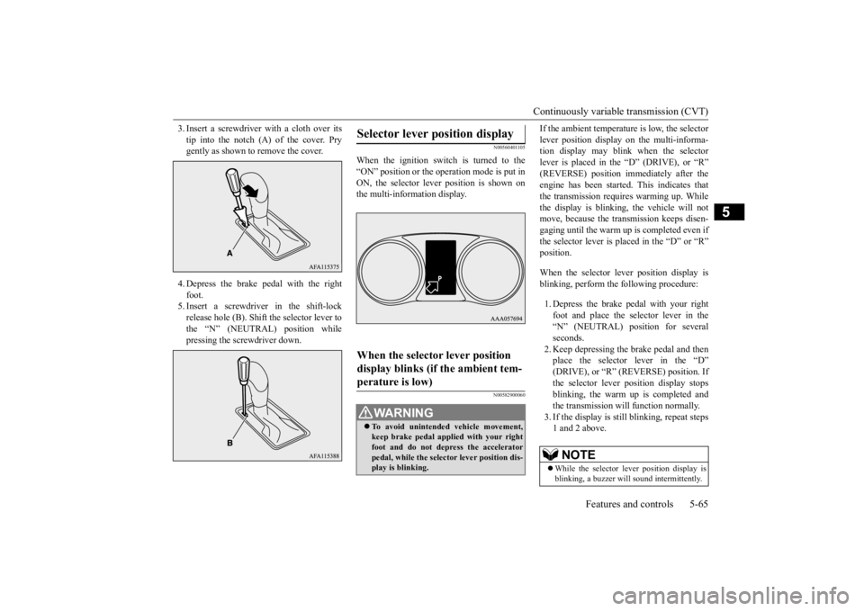
3. Insert a screwdriver with a cloth over its tip into the notch (A) of the cover. Pry gently as shown to remove the cover. 4. Depress the brake pedal with the right foot. 5. Insert a screwdriver in the shift-lockrelease hole (B). Shift the selector lever to the “N” (NEUTRAL) position while pressing the screwdriver down.
N00560401105
When the ignition switch is turned to the“ON” position or the operation mode is put inON, the selector lever position is shown on the multi-information display.
N00582900060
If the ambient temperature is low, the selector lever position display on the multi-informa- tion display may blink when the selector lever is placed in the “D” (DRIVE), or “R”(REVERSE) position immediately after the engine has been started. This indicates that the transmission requires warming up. Whilethe display is blinking, the vehicle will not move, because the transmission keeps disen- gaging until the warm up is completed even ifthe selector lever is placed in the “D” or “R”position. When the selector lever position display is blinking, perform the following procedure: 1. Depress the brake pedal with your right foot and place the selector lever in the“N” (NEUTRAL) position for several seconds. 2. Keep depressing the brake pedal and thenplace the selector lever in the “D” (DRIVE), or “R” (R
EVERSE) position. If
the selector lever position display stopsblinking, the warm up is completed and the transmission will function normally. 3. If the display is sti
ll blinking, repeat steps
1 and 2 above.
Selector lever position display When the selector lever position display blinks (if the ambient tem-perature is low)
WA R N I N G To avoid unintended vehicle movement, keep brake pedal applied with your right foot and do not depress the accelerator pedal, while the selector lever position dis-play is blinking.
NOTE
While the selector lever position display is blinking, a buzzer will sound intermittently.
BK0277700US.bo
ok 65 ページ 2019年3月8日 金曜日 午前9時23分