MITSUBISHI ENDEAVOR 2004 Service Repair Manual
Manufacturer: MITSUBISHI, Model Year: 2004, Model line: ENDEAVOR, Model: MITSUBISHI ENDEAVOR 2004Pages: 3870, PDF Size: 98.47 MB
Page 341 of 3870
1. Before proceeding, see AIR BAG SAFETY PRECAUTIONS
. If DTC 34 is
retrieved, go to next step. If DTC 34 is not retrieved, go to step 3 .
2. Inspect ECU SRS connector C-25. See SRS ELECTRONIC CONTROL
UNIT (SRS ECU)
under REMOVAL & INSTALLATION. See Fig. 19
. If
connector is not connected properly, connect properly. Go to step 6 . If
connector is connected properly, go to next step.
3. Disconnect negative battery cable. Disconnect SRS ECU connector C-25 and
driver side impact air bag module connector D-26. See SIDE IMPACT AIR
BAG MODULE
under REMOVAL & INSTALLATION. Reconnect both
connectors. Connect negative battery cable. Using scan tool, erase then retrieve
DTCs. If DTC 81 is retrieved, go to next step. If DTC 81 is not retrieved,
system is normal at this time.
4. Disconnect driver side impact air bag module connector D-26. Connect Load
Resistor (MB991865) to Load Resistor Harness (MB991866). Connect load
resistor harness to connector D-26 by backprobing connector. Connect
negative battery cable. Using scan tool, erase then retrieve DTCs. If DTC 81 is
retrieved, go to next step. If DTC 81 is not retrieved, replace driver side impact
air bag module. Go to step 6 .
5. Disconnect SRS ECU connector C-25 and driver side impact air bag module
connector D-26. Insert a cable tie or similar insulator between terminal No. 21
(Yellow/Green wire) and No. 22 (Yellow/Red wire) of SRS ECU connector to
release shorting bar. See Fig. 21
. Check for continuity between terminals No.
21 and 22. If continuity is found, replace wire harness between SRS ECU and
driver side impact air bag module. Go to next step. If continuity is not found,
erase then retrieve DTCs. If DTC 81 is retrieved, replace SRS ECU. Go to next
step.
6. Reconnect all SRS components. Activate air bag system. Using scan tool, erase
then retrieve DTCs. If DTC 81 is retrieved, go to step 1 . If DTC 81 is not
retrieved, system is normal at this time. Intermittent condition may exist.
DTC 82: DRIVER SIDE IMPACT AIR BAG MODULE OPEN CIRCUIT 1. Before proceeding, see AIR BAG SAFETY PRECAUTIONS
. Disconnect
negative battery cable. Disconnect driver side impact air bag module connector
D-26. See SIDE IMPACT AIR BAG MODULE
under REMOVAL &
2004 Mitsubishi Endeavor Limited
2004 ACCESSORIES/SAFETY EQUIPMENT Mitsubishi - Air Bag Restraint Systems
Page 342 of 3870
INSTALLATION. See Fig. 19
. Connect Load Resistor (MB991865) to Load
Resistor Harness (MB991866). Connect Load Resistor Harness to connector
D-26 by backprobing connector. Connect negative battery cable. Using scan
tool, erase then retrieve DTCs. If DTC 82 is retrieved, go to next step. If DTC
82 is not retrieved, replace driver side impact air bag module. Go to next step.
2. Disconnect SRS ECU connector C-25 and driver side impact air bag module
connector D-26. See SRS ELECTRONIC CONTROL UNIT (SRS ECU)
under REMOVAL & INSTALLATION. Check Yellow/Green wire between
SRS ECU connector C-25, terminal No. 21 and side impact connector D-26,
terminal No. 1 for continuity. See Fig. 21
& Fig. 28
. Check Yellow/Red wire
between SRS ECU connector C-25, terminal No. 22 and side impact connector
D-26, terminal No. 2 for continuity. If continuity exists in both wires, go to
next step. If continuity does not exist in both wires, replace wire harness
between SRS ECU and driver side impact air bag module. Go to next step.
3. Reconnect all SRS components. Activate air bag system. Using scan tool, erase
then retrieve DTCs. If DTC 82 is retrieved, go to step 1 . If DTC 82 is not
retrieved, system is normal at this time. Intermittent condition may exist.
DTC 83 & 84: PASSENGER SIDE IMPACT AIR BAG MODULE If DTC 83 or 84 is present, replace SRS ECU. See SRS ELECTRONIC CONTROL UNIT (SRS ECU)
under REMOVAL & INSTALLATION.
DTC 85: DRIVER SIDE IMPACT AIR BAG MODULE SHORT TO VOLTAGE 1. Before proceeding, see AIR BAG SAFETY PRECAUTIONS
. Disable air
bag system. See DISABLING & ACTIVATING AIR BAG SYSTEM
.
Disconnect passenger side impact air bag module connector D-26. See SIDE
IMPACT AIR BAG MODULE
under REMOVAL & INSTALLATION. See
Fig. 19
. Connect Load Resistor (MB991865) to Load Resistor Harness
(MB991866). Connect load resistor harness to connector D-26 by backprobing
connector. Connect negative battery cable. Using scan tool, erase then retrieve
DTCs. If DTC 85 is retrieved, go to next step. If DTC 85 is not retrieved,
replace driver side impact air bag module. Go to step 3 .
2. Disconnect SRS ECU connector C-25 and driver side impact air bag module
connector D-26. See SRS ELECTRONIC CONTROL UNIT (SRS ECU)
2004 Mitsubishi Endeavor Limited
2004 ACCESSORIES/SAFETY EQUIPMENT Mitsubishi - Air Bag Restraint Systems
Page 343 of 3870
under REMOVAL & INSTALLATION. Turn ignition on. Check for voltage
between ground and connector C-25, terminals No. 21 (Yellow/Green wire)
and No. 22 (Yellow/Red wire). See Fig. 21
. If voltage is measured at either
terminal, replace wire harness between SRS ECU and driver side impact air
bag module. Go to next step. If voltage is not measured, erase, then retrieve
DTCs. If DTC 85 is retrieved, replace SRS ECU. Go to next step.
3. Reconnect all SRS components. Activate air bag system. Using scan tool, erase
then retrieve DTCs. If DTC 85 is retrieved, go to step 1 . If DTC 85 is not
retrieved, system is normal at this time. Intermittent condition may exist.
DTC 86: DRIVER SIDE IMPACT AIR BAG MODULE SHORT TO GROUND 1. Before proceeding, see AIR BAG SAFETY PRECAUTIONS
. Disable air
bag system. See DISABLING & ACTIVATING AIR BAG SYSTEM
.
Disconnect driver side impact air bag module connector D-26. See SIDE
IMPACT AIR BAG MODULE
under REMOVAL & INSTALLATION. See
Fig. 19
. Connect Load Resistor (MB991865) to Load Resistor Harness
(MB991866). Connect load resistor harness to connector D-26 by backprobing
connector. Connect negative battery cable. Using scan tool, erase then retrieve
DTCs. If DTC 86 is retrieved, go to next step. If DTC 86 is not retrieved,
replace driver side impact air bag module. Go to step 3 .
2. Disconnect SRS ECU connector C-25 and driver side impact air bag module
connector D-26. See SRS ELECTRONIC CONTROL UNIT (SRS ECU)
under REMOVAL & INSTALLATION. Check for continuity between ground
and connector C-25, terminal No. 21 (Yellow/Green wire) and No. 22
(Yellow/Red wire). See Fig. 21
. If continuity is found between ground and
either wire, replace wire harness between SRS ECU and driver side impact air
bag module. Go to next step. If continuity does not exist, erase, then retrieve
DTCs. If DTC 86 is retrieved, replace SRS ECU. Go to next step.
3. Reconnect all SRS components. Activate air bag system. Using scan tool, erase
then retrieve DTCs. If DTC 86 is retrieved, go to step 1 . If DTC 86 is not
retrieved, system is normal at this time. Intermittent condition may exist.
DTC 89 & 96: PASSENGER SIDE IMPACT AIR BAG MODULE SENSOR COMMUNICATION
CIRCUIT 1. Before
proceedin
g, see AIR BAG SAFETY PRECAUTIONS. Disable air
2004 Mitsubishi Endeavor Limited
2004 ACCESSORIES/SAFETY EQUIPMENT Mitsubishi - Air Bag Restraint Systems
Page 344 of 3870
bag system. See DISABLING & ACTIVATING AIR BAG SYSTE
M . Go
to next step.
2. Replace passenger side impact sensor with driver side impact sensor. See
SIDE IMPACT SENSOR
under REMOVAL & INSTALLATION. Connect
negative battery cable. Using scan tool, erase then retrieve DTCs. If DTCs 89
or 96 are erased and DTCs 79 or 93 are retrieved, replace passenger side
impact sensor. If DTC 89 or 96 are not erased and DTC 79 or 93 are not
retrieved, go to next step.
3. Check wire harness between SRS ECU connector C-25 and passenger side
impact sensor connector D-18. See SRS ELECTRONIC CONTROL UNIT
(SRS ECU)
under REMOVAL & INSTALLATION. See Fig. 19
. Replace
wire harness, if damaged. Go to next step. If wire harness is okay, go to next
step.
4. Using scan tool, erase then retrieve DTCs. If DTC 89 or 96 is retrieved, replace
SRS ECU. If DTC 89 or 96 is not retrieved, system is normal at this time.
Intermittent condition may exist.
DTC 91: DRIVER SIDE IMPACT AIR BAG MODULE SENSOR POWER SUPPLY CIRCUIT 1. Before proceeding, see AIR BAG SAFETY PRECAUTIONS
. Disable air
bag system. See DISABLING & ACTIVATING AIR BAG SYSTEM
. Go
to next step.
2. Disconnect driver side impact sensor connector D-23. See SIDE IMPACT
SENSOR
under REMOVAL & INSTALLATION. See Fig. 19
. Connect
negative battery cable. Turn ignition on. Measure voltage between connector
D-24, terminal No. 2 (Black/Blue wire) and ground. See Fig. 29 . Turn ignition
off. If voltage is 9 volts or more, replace side impact sensor. If voltage is less
than 9 volts, go to next step.
3. Check wire harness between SRS ECU connector C-25 and driver side impact
sensor connector D-23 for an open or short circuit. If an open or short circuit is
found, replace wire harness. Go to next step. If wire harness is okay, go to next
step.
4. Reconnect all SRS components. Activate air bag system. Using scan tool, erase
then retrieve DTCs. If DTC 91 is retrieved, go to step 1 . If DTC 91 is not
retrieved, s
ystem is normal at this time. Intermit
tent condition ma
y exist.
2004 Mitsubishi Endeavor Limited
2004 ACCESSORIES/SAFETY EQUIPMENT Mitsubishi - Air Bag Restraint Systems
Page 345 of 3870
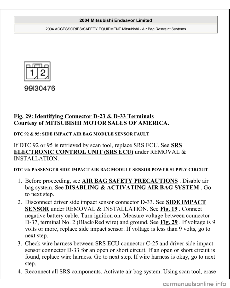
Fig. 29: Identifying Connector D
-23 & D
-33 Terminals
Courtesy of MITSUBISHI MOTOR SALES OF AMERICA.
DTC 92 & 95: SIDE IMPACT AIR BAG MODULE SENSOR FAULT If DTC 92 or 95 is retrieved by scan tool, replace SRS ECU. See SRS ELECTRONIC CONTROL UNIT (SRS ECU)
under REMOVAL &
INSTALLATION.
DTC 94: PASSENGER SIDE IMPACT AIR BAG MODULE SENSOR POWER SUPPLY CIRCUIT 1. Before proceeding, see AIR BAG SAFETY PRECAUTIONS
. Disable air
bag system. See DISABLING & ACTIVATING AIR BAG SYSTEM
. Go
to next step.
2. Disconnect driver side impact sensor connector D-33. See SIDE IMPACT
SENSOR
under REMOVAL & INSTALLATION. See Fig. 19
. Connect
negative battery cable. Turn ignition on. Measure voltage between connector
D-37, terminal No. 2 (Black/Red wire) and ground. See Fig. 29 . If voltage is 9
volts or more, replace side impact sensor. If voltage is less than 9 volts, go to
next step.
3. Check wire harness between SRS ECU connector C-25 and driver side impact
sensor connector D-33 for an open or short circuit. If an open or short circuit is
found, replace wire harness. Go to next step. If wire harness is okay, go to next
step.
4. Reconnect all SRS com
ponents. Activate air ba
g system. Usin
g scan tool, erase
2004 Mitsubishi Endeavor Limited
2004 ACCESSORIES/SAFETY EQUIPMENT Mitsubishi - Air Bag Restraint Systems
Page 346 of 3870
then retrieve DTCs. If DTC 94 is retrieved, go to step 1 . If DTC 94 is not
retrieved, system is normal at this time. Intermittent condition may exist.
DIAGNOSTIC TESTS (DUAL-STAGE AIR BAG SYSTEM) INSPECTION PROCEDURE 1 Connect scan tool to Data Link Connector (DLC). See INITIAL SRS DIAGNOSTIC PROCEDURE
under DIAGNOSTICS. Turn ignition on. If scan
tool is able to diagnose CAN bus lines and CAN bus lines are satisfactory, inspect
and repair power circuits. Go to INSPECTION PROCEDURE 2
. If scan tool
cannot diagnose CAN bus lines, inspect and repair CAN bus lines.
INSPECTION PROCEDURE 2 1. Connect scan tool to Data Link Connector (DLC). See INITIAL SRS
DIAGNOSTIC PROCEDURE
under DIAGNOSTICS. Disconnect SRS ECU
connector C-26. See SRS ELECTRONIC CONTROL UNIT (SRS ECU)
under REMOVAL & INSTALLATION. See Fig. 30
. Measure resistance
between ground and connector C-26, terminal No. 40 (Black wire). If
resistance is 2 ohms or less, go to next step. If resistance is more than 2 ohms,
repair wiring harness between SRS ECU and ground. See WIRE REPAIR
.
2. Inspect Black/White wire and Black/Yellow wire between connector C-26 and
ignition switch connector C-308, including junction block connectors C-211
and C-215. See Fig. 22
. If wires are okay, go to next step. If wires are not
okay, replace wire harness.
3. Inspect battery. If battery is in good condition, go to next step. If battery is not
in good condition, charge or replace battery as appropriate. Go to step 5 .
4. Inspect charging system. If charging system is okay, go to next step. If
charging system is not okay, repair charging system as appropriate. Go to next
step.
5. Retest SRS system. If scan tool can communicate with SRS ECU, an
intermittent condition may have existed. If scan tool cannot communicate with
NOTE: If scan tool cannot communicate with SRS ECU, CAN bus
line may be defective.
2004 Mitsubishi Endeavor Limited
2004 ACCESSORIES/SAFETY EQUIPMENT Mitsubishi - Air Bag Restraint Systems
Page 347 of 3870
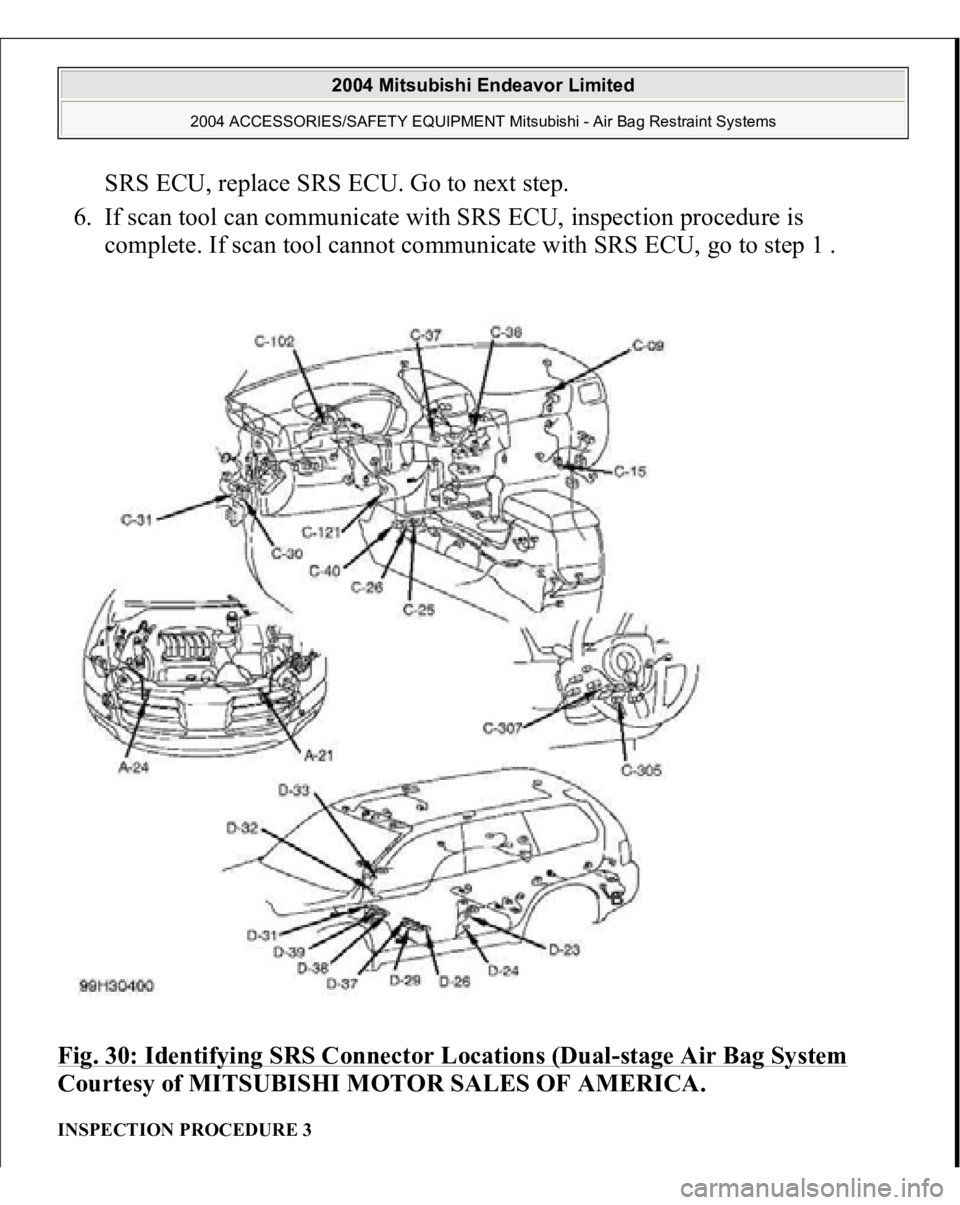
SRS ECU, replace SRS ECU. Go to next step.
6. If scan tool can communicate with SRS ECU, inspection procedure is
complete. If scan tool cannot communicate with SRS ECU, go to step 1 .
Fig. 30: Identifying SRS Connector Locations (Dual
-stage Air Bag System
Courtesy of MITSUBISHI MOTOR SALES OF AMERICA.
INSPECTION PROCEDURE 3
2004 Mitsubishi Endeavor Limited
2004 ACCESSORIES/SAFETY EQUIPMENT Mitsubishi - Air Bag Restraint Systems
Page 348 of 3870
1. Connect scan tool to Data Link Connector (DLC). See INITIAL SRS
DIAGNOSTIC PROCEDURE
under DIAGNOSTICS. If scan tool is able to
diagnose CAN bus lines and CAN bus lines are satisfactory, go to next step. If
scan tool cannot diagnose CAN bus lines, repair CAN bus lines. Go to next
step.
2. Using scan tool, retrieve combination meter Diagnostic Trouble Codes (DTCs).
If DTC U1112 is retrieved, replace SRS ECU. If DTC U1112 is not retrieved,
replace combination meter.
INSPECTION PROCEDURE 4 1. Connect scan tool to Data Link Connector (DLC). See INITIAL SRS
DIAGNOSTIC PROCEDURE
under DIAGNOSTICS. If scan tool is able to
diagnose CAN bus lines and CAN bus lines are satisfactory, go to next step. If
scan tool cannot diagnose CAN bus lines, repair CAN bus lines. Go to next
step.
2. Using scan tool, retrieve combination meter Diagnostic Trouble Codes (DTCs).
If DTC U1112 is retrieved, replace SRS ECU. If DTC U1112 is not retrieved,
replace combination meter.
DTC B1400: DRIVER-SIDE AIR BAG MODULE FIRST-STAGE SHORT CIRCUIT 1. Connect scan tool to Data Link Connector (DLC). See INITIAL SRS
DIAGNOSTIC PROCEDURE
under DIAGNOSTICS. If scan tool is able to
diagnose CAN bus lines and CAN bus lines are satisfactory, go to next step. If
scan tool cannot diagnose CAN bus lines, repair CAN bus lines. Go to next
step.
2. Erase, then retrieve DTCs. Turn ignition off. If DTC B1400 is retrieved, go to
next step. If DTC B1400 is not retrieved, an intermittent condition may exist.
3. Turn ignition on. If DTC B1519 is retrieved by scan tool, go to next step. If
DTC B1519 is not retrieved by scan tool, go to step 5 .
4. Inspect SRS ECU connector C-26. See SRS ELECTRONIC CONTROL
UNIT (SRS ECU)
under REMOVAL & INSTALLATION. See Fig. 30
. If
connector is connected correctly, go to next step. If connector is not connected
correctly, reconnect correctly. Go to step 1
0.
2004 Mitsubishi Endeavor Limited
2004 ACCESSORIES/SAFETY EQUIPMENT Mitsubishi - Air Bag Restraint Systems
Page 349 of 3870
5. Disconnect negative battery cable. Disconnect, then reconnect SRS connectors
C-26, C-307 and C-305. Connect negative battery cable. Using scan tool, erase,
then retrieve DTCs. If DTC B1400 is retrieved, go to next step. If DTC B1400
is not retrieved, intermittent condition may have existed.
6. Disconnect negative battery cable. Remove driver-side air bag module. See
DRIVER
-SIDE AIR BAG MODULE & CLOCKSPRING
under
REMOVAL & INSTALLATION. Disconnect driver-side air bag module
connector C-305. Connect Load Resistor (MB991865) to Load Resistor
Adapter (MB991866). Insert load resistor adapter leads into harness-side
terminals No. 1 (Yellow/Red wire) and No. 2 (Yellow/Blue wire) of connector
C-305. See Fig. 31
. Connect negative battery cable. Erase, then retrieve DTCs.
If DTC B1400 is retrieved, go to next step. If DTC B1400 is not retrieved,
replace driver-side air bag module.
7. Disconnect negative battery cable. Disconnect lower clockspring connector C-
307. Connect load resistor and load resistor adapter to terminals No. 13
(Yellow/Black wire) and No. 14 (Yellow wire) on harness-side of connector C-
307. See Fig. 32 . Reconnect negative battery cable. Erase, then retrieve DTCs.
If DTC B1400 is not retrieved, replace clockspring. Go to step 10 . If DTC
B1400 is retrieved, go to next step.
8. Disconnect negative battery cable. Remove load resistor and load resistor
adapter from clockspring connector C-307. Disconnect SRS ECU connector C-
26. Release SRS ECU connector shorting bar using a cable tie. Measure
resistance between SRS ECU connector terminals No. 36 (Yellow/Black wire)
and No. 37 (Yellow wire). See Fig. 33
. If continuity exits, go to next step. If
continuity does not exist, reconnect SRS components. Erase, then retrieve
DTCs. If DTC B1400 is retrieved, replace SRS ECU. Go to step 10 .
9. Replace wire harness between SRS ECU and clockspring. Go to next step.
10. Reconnect all SRS components. Activate air bag system. Using scan tool,
retrieve DTCs. If DTC B1400 is retrieved, go to step 1 . If DTC B1400 is not
retrieved, s
ystem is normal at this time.
2004 Mitsubishi Endeavor Limited
2004 ACCESSORIES/SAFETY EQUIPMENT Mitsubishi - Air Bag Restraint Systems
Page 350 of 3870
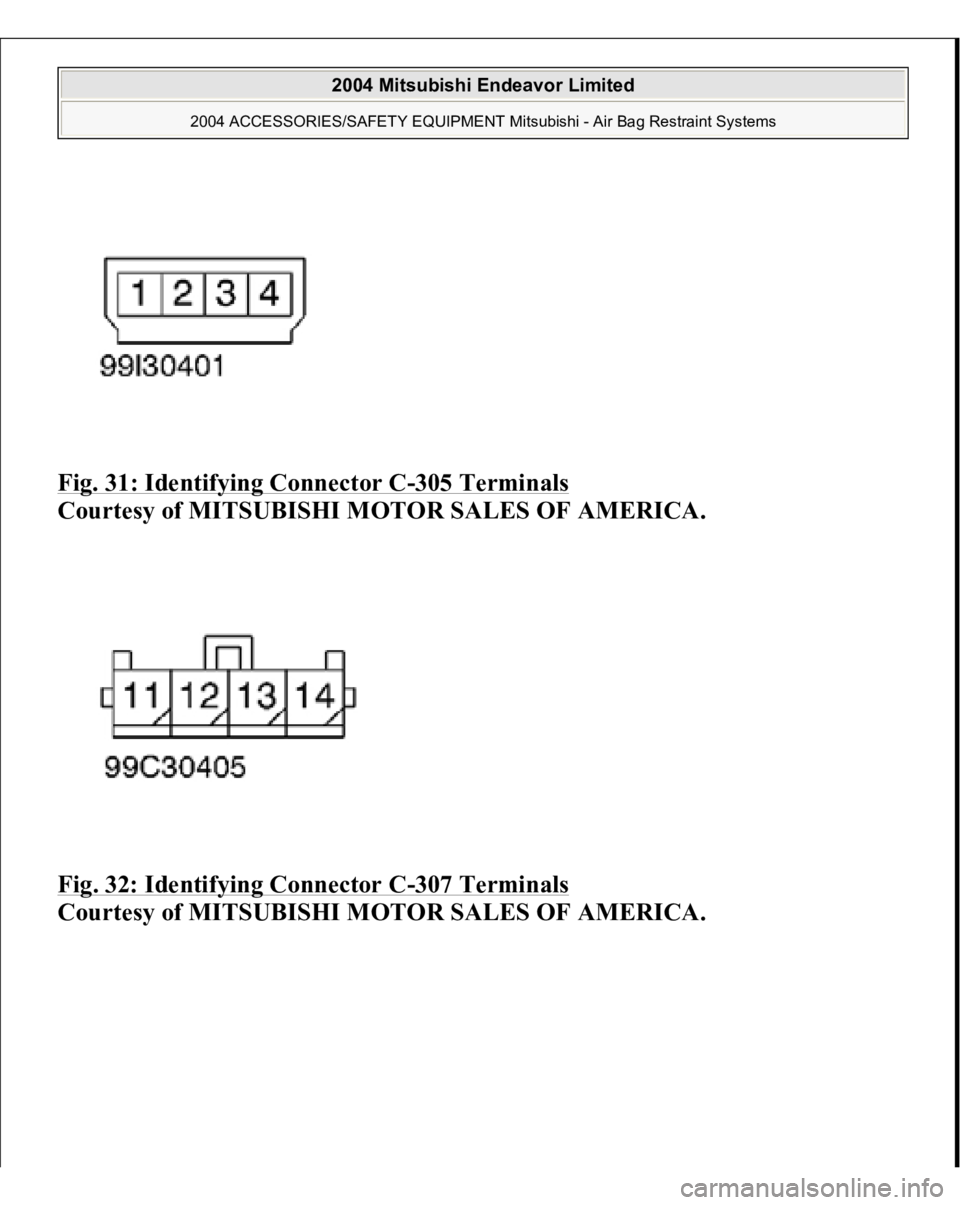
Fig. 31: Identifying Connector C
-305 Terminals
Courtesy of MITSUBISHI MOTOR SALES OF AMERICA.
Fig. 32: Identifying Connector C
-307 Terminals
Courtesy of MITSUBISHI MOTOR SALES OF AMERICA.
2004 Mitsubishi Endeavor Limited
2004 ACCESSORIES/SAFETY EQUIPMENT Mitsubishi - Air Bag Restraint Systems