MITSUBISHI ENDEAVOR 2004 Service Repair Manual
Manufacturer: MITSUBISHI, Model Year: 2004, Model line: ENDEAVOR, Model: MITSUBISHI ENDEAVOR 2004Pages: 3870, PDF Size: 98.47 MB
Page 351 of 3870
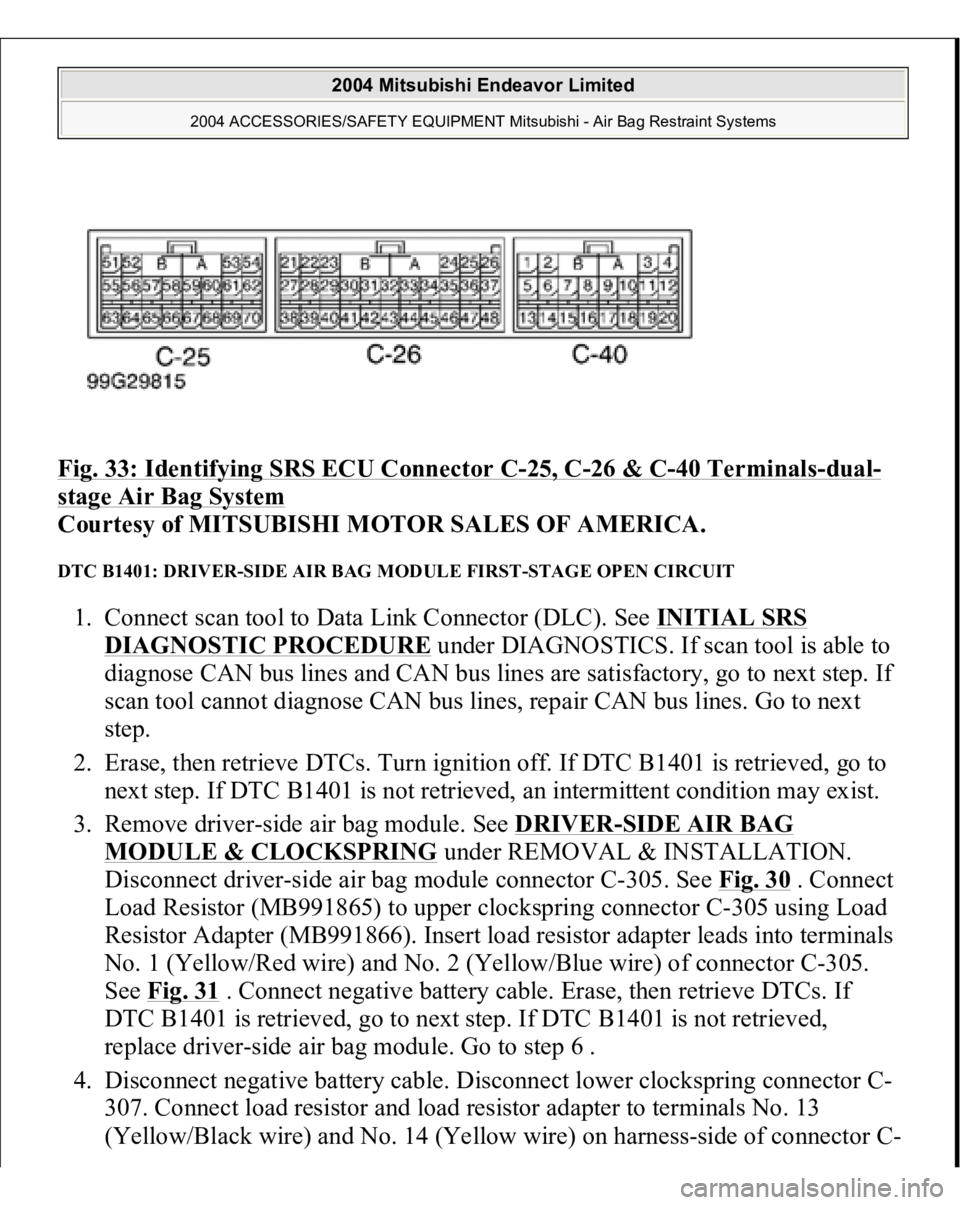
Fig. 33: Identifying SRS ECU Connector C
-25, C
-26 & C
-40 Terminals
-dual
-
stage Air Bag System
Courtesy of MITSUBISHI MOTOR SALES OF AMERICA.
DTC B1401: DRIVER-SIDE AIR BAG MODULE FIRST-STAGE OPEN CIRCUIT 1. Connect scan tool to Data Link Connector (DLC). See INITIAL SRS
DIAGNOSTIC PROCEDURE
under DIAGNOSTICS. If scan tool is able to
diagnose CAN bus lines and CAN bus lines are satisfactory, go to next step. If
scan tool cannot diagnose CAN bus lines, repair CAN bus lines. Go to next
step.
2. Erase, then retrieve DTCs. Turn ignition off. If DTC B1401 is retrieved, go to
next step. If DTC B1401 is not retrieved, an intermittent condition may exist.
3. Remove driver-side air bag module. See DRIVER
-SIDE AIR BAG
MODULE & CLOCKSPRING
under REMOVAL & INSTALLATION.
Disconnect driver-side air bag module connector C-305. See Fig. 30
. Connect
Load Resistor (MB991865) to upper clockspring connector C-305 using Load
Resistor Adapter (MB991866). Insert load resistor adapter leads into terminals
No. 1 (Yellow/Red wire) and No. 2 (Yellow/Blue wire) of connector C-305.
See Fig. 31
. Connect negative battery cable. Erase, then retrieve DTCs. If
DTC B1401 is retrieved, go to next step. If DTC B1401 is not retrieved,
replace driver-side air bag module. Go to step 6 .
4. Disconnect negative battery cable. Disconnect lower clockspring connector C-
307. Connect load resistor and load resistor adapter to terminals No. 13
(Yellow/Black wire
) and No. 14
(Yellow wire
) on ha
rnes
s-side of connector
C-
2004 Mitsubishi Endeavor Limited
2004 ACCESSORIES/SAFETY EQUIPMENT Mitsubishi - Air Bag Restraint Systems
Page 352 of 3870
307. See Fig. 32
. Reconnect negative battery cable. Erase, then retrieve DTCs.
If DTC B1401 is not retrieved, replace clockspring. Go to step 6 . If DTC
B1401 is retrieved, go to next step.
5. Disconnect negative battery cable. Remove load resistor and load resistor
adapter from C-307. Disconnect SRS ECU connector C-26. Release SRS ECU
connector shorting bar using a cable tie. Measure resistance of Yellow/Black
wire between SRS ECU connector terminal No. 36 and terminal No. 13 of
lower clockspring connector C307. See Fig. 33
. Measure resistance of Yellow
wire between SRS ECU connector terminal No. 37 and terminal No. 14 of
lower clockspring connector C307. If resistance is less than 2 ohms in both
wires, reconnect components. Erase, then retrieve DTCs. If DTC B1401 is
retrieved, replace SRS ECU. Go to next step. If resistance is 2 ohms or more in
either wire, replace wire harness between SRS ECU and clockspring. Go to
next step.
6. Reconnect all SRS components. Activate air bag system. Using scan tool,
retrieve DTCs. If DTC B1401 is retrieved, go to step 1 . If DTC B1401 is not
retrieved, system is normal at this time.
DTC B1402: DRIVER-SIDE AIR BAG MODULE FIRST-STAGE STAGE CIRCUIT SHORT TO
VOLTAGE 1. Connect scan tool to Data Link Connector (DLC). See INITIAL SRS
DIAGNOSTIC PROCEDURE
under DIAGNOSTICS. If scan tool is able to
diagnose CAN bus lines and CAN bus lines are satisfactory, go to next step. If
scan tool cannot diagnose CAN bus lines, repair CAN bus lines. Go to next
step.
2. Erase, then retrieve DTCs. Turn ignition off. If DTC B1402 is retrieved, go to
next step. If DTC B1402 is not retrieved, an intermittent condition may exist.
3. Remove driver-side air bag module. See DRIVER
-SIDE AIR BAG
MODULE & CLOCKSPRING
under REMOVAL & INSTALLATION.
Disconnect driver-side air bag module connector C-305. See Fig. 30
. Connect
Load Resistor (MB991865) to upper clockspring connector using Load
Resistor Adapter (MB991866). Insert load resistor adapter leads into terminals
No. 1 (Yellow/Red wire) and No. 2 (Yellow/Blue wire) of connector C-305.
See Fig. 31
. Connect negative battery cable. Erase, then retrieve DTCs. If
DTC B1402 is retrieved,
go to next ste
p. If DTC B1402 is not retrieved,
2004 Mitsubishi Endeavor Limited
2004 ACCESSORIES/SAFETY EQUIPMENT Mitsubishi - Air Bag Restraint Systems
Page 353 of 3870
replace driver-side air bag module. Go to step 7 .
4. Disconnect negative battery cable. Disconnect lower clockspring connector C-
307. Connect load resistor and load resistor adapter to terminals No. 13
(Yellow/Black wire) and No. 14 (Yellow wire) on harness-side of connector C-
307. See Fig. 32
. Reconnect negative battery cable. Erase, then retrieve DTCs.
If DTC B1402 is not retrieved, replace clockspring. Go to step 7 . If DTC
B1402 is retrieved, go to next step.
5. Disconnect negative battery cable. Disconnect clockspring connector C-307.
Disconnect SRS ECU connector. C-26. Release SRS ECU connector shorting
bar using a cable tie. Measure voltage between ground and SRS ECU
connector C-26, terminal No. 36 (Yellow/Black wire) and No. 37 (Yellow
wire). See Fig. 33 . If voltage is measured at either terminal, go to next step. If
zero volt is measured at both terminals, reconnect components. Erase, then
retrieve DTCs. If DTC B1402 is retrieved, replace SRS ECU. Go to step 7 .
6. Replace wire harness between SRS ECU and clockspring. Go to next step.
7. Reconnect all SRS components. Activate air bag system. Using scan tool,
retrieve DTCs. If DTC B1402 is retrieved, go to step 1 . If DTC B1402 is not
retrieved, system is normal at this time.
DTC B1403: DRIVER-SIDE AIR BAG MODULE FIRST-STAGE SHORT TO GROUND 1. Connect scan tool to Data Link Connector (DLC). See INITIAL SRS
DIAGNOSTIC PROCEDURE
under DIAGNOSTICS. If scan tool is able to
diagnose CAN bus lines and CAN bus lines are satisfactory, go to next step. If
scan tool cannot diagnose CAN bus lines, repair CAN bus lines. Go to next
step.
2. Erase, then retrieve DTCs. Turn ignition off. If DTC B1403 is retrieved, go to
next step. If DTC B1403 is not retrieved, an intermittent condition may exist.
3. Remove driver-side air bag module. See DRIVER
-SIDE AIR BAG
MODULE & CLOCKSPRING
under REMOVAL & INSTALLATION.
Disconnect driver-side air bag module connector C-305. See Fig. 30
. Connect
Load Resistor (MB991865) to upper clockspring connector using Load
Resistor Adapter (MB991866). Insert load resistor adapter leads into terminals
No. 1 (Yellow/Red wire) and No. 2 (Yellow/Blue wire) of connector C-305.
See Fig. 31
. Connect ne
gative batter
y cable. Erase, then retrieve DTCs. I
f
2004 Mitsubishi Endeavor Limited
2004 ACCESSORIES/SAFETY EQUIPMENT Mitsubishi - Air Bag Restraint Systems
Page 354 of 3870
DTC B1403 is retrieved, go to next step. If DTC B1403 is not retrieved,
replace driver-side air bag module. Go to step 7 .
4. Disconnect negative battery cable. Disconnect lower clockspring connector C-
307. Connect load resistor and load resistor adapter to terminals No. 13
(Yellow/Black wire) and No. 14 (Yellow wire) on harness-side of connector C-
307. See Fig. 32
. Reconnect negative battery cable. Erase, then retrieve DTCs.
If DTC B1403 is not retrieved, replace clockspring. Go to step 7 . If DTC
B1403 is retrieved, go to next step.
5. Disconnect negative battery cable. Disconnect clockspring connector C-307.
Disconnect SRS ECU connector C-26. Release SRS ECU connector shorting
bar using a cable tie. Measure resistance between ground and SRS ECU
connector C-26, terminal No. 36 (Yellow/Black wire) and terminal No. 37
(Yellow wire). See Fig. 33
. If resistance is not infinite at both terminals, go to
next step. If resistance infinite at both terminals, reconnect components. Erase,
then retrieve DTCs. If DTC B1403 is retrieved, replace SRS ECU. Go to step
7 .
6. Replace wire harness between SRS ECU and clockspring. Go to next step.
7. Reconnect all SRS components. Activate air bag system. Using scan tool,
retrieve DTCs. If DTC B1403 is retrieved, go to step 1 . If DTC B1403 is not
retrieved, system is normal at this time.
DTC B1404: DRIVER-SIDE AIR BAG MODULE FIRST-STAGE ACTIVATION CIRCUIT SHORT 1. Connect scan tool to Data Link Connector (DLC). See INITIAL SRS
DIAGNOSTIC PROCEDURE
under DIAGNOSTICS. If scan tool is able to
diagnose CAN bus lines and CAN bus lines are satisfactory, go to next step. If
scan tool cannot diagnose CAN bus lines, repair CAN bus lines. Go to next
step.
2. Erase, then retrieve DTCs. If DTC B1404 is retrieved, replace SRS ECU. See
SRS ELECTRONIC CONTROL UNIT (SRS ECU)
under REMOVAL &
INSTALLATION. If DTC B1404 is not retrieved, an intermittent condition
may exist.
DTC B1405: DRIVER-SIDE AIR BAG MODULE FIRST-STAGE ACTIVATION CIRCUIT OPEN 1. Connect scan tool to Data Link Connector
(DLC
). SeeINITIAL SRS
2004 Mitsubishi Endeavor Limited
2004 ACCESSORIES/SAFETY EQUIPMENT Mitsubishi - Air Bag Restraint Systems
Page 355 of 3870
DIAGNOSTIC PROCEDURE
under DIAGNOSTICS. If scan tool is able to
diagnose CAN bus lines and CAN bus lines are satisfactory, go to next step. If
scan tool cannot diagnose CAN bus lines, repair CAN bus lines. Go to next
step.
2. Erase, then retrieve DTCs. If DTC B1405 is retrieved, replace SRS ECU. See
SRS ELECTRONIC CONTROL UNIT (SRS ECU)
under REMOVAL &
INSTALLATION. If DTC B1405 is not retrieved, an intermittent condition
may exist.
DTC B1406: FRONT IMPACT G SENSOR (RH) FAILURE 1. Connect scan tool to Data Link Connector (DLC). See INITIAL SRS
DIAGNOSTIC PROCEDURE
under DIAGNOSTICS. If scan tool is able to
diagnose CAN bus lines and CAN bus lines are satisfactory, go to next step. If
scan tool cannot diagnose CAN bus lines, repair CAN bus lines. Go to next
step.
2. Erase, then retrieve DTCs. If DTC B1406 is retrieved, go to next step. If DTC
B1406 is not retrieved, an intermittent condition may exist.
3. Replace passenger-side front impact sensor. See FRONT IMPACT SENSOR
under REMOVAL & INSTALLATION. Reconnect SRS components. Erase,
then retrieve DTCs. If DTC B1406 is retrieved, replace SRS ECU. See SRS
ELECTRONIC CONTROL UNIT (SRS ECU)
under REMOVAL &
INSTALLATION. If DTC B1406 is not retrieved, system is normal at this
time.
DTC B1407: FRONT IMPACT SENSOR (RH) VOLTAGE ERROR 1. Connect scan tool to Data Link Connector (DLC). See INITIAL SRS
DIAGNOSTIC PROCEDURE
under DIAGNOSTICS. If scan tool is able to
diagnose CAN bus lines and CAN bus lines are satisfactory, go to next step. If
scan tool cannot diagnose CAN bus lines, repair CAN bus lines. Go to next
step.
2. Erase, then retrieve DTCs. If DTC B1407 is retrieved, go to next step. If DTC
B1407 is not retrieved, an intermittent condition may exist.
3. Disconnect negative battery cable. Disconnect passenger-side front impact
sensor connector
A-24. See Fig. 30
. See FRONT IMPACT SENSOR
under
2004 Mitsubishi Endeavor Limited
2004 ACCESSORIES/SAFETY EQUIPMENT Mitsubishi - Air Bag Restraint Systems
Page 356 of 3870
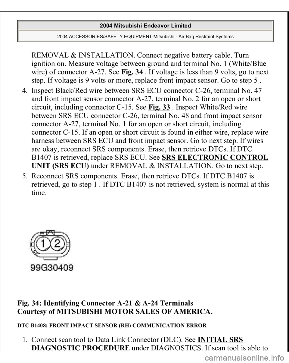
REMOVAL & INSTALLATION. Connect negative battery cable. Turn
ignition on. Measure voltage between ground and terminal No. 1 (White/Blue
wire) of connector A-27. See Fig. 34
. If voltage is less than 9 volts, go to next
step. If voltage is 9 volts or more, replace front impact sensor. Go to step 5 .
4. Inspect Black/Red wire between SRS ECU connector C-26, terminal No. 47
and front impact sensor connector A-27, terminal No. 2 for an open or short
circuit, including connector C-15. See Fig. 33
. Inspect White/Red wire
between SRS ECU connector C-26, terminal No. 48 and front impact sensor
connector A-27, terminal No. 1 for an open or short circuit, including
connector C-15. If an open or short circuit is found in either wire, replace wire
harness between SRS ECU and front impact sensor. Go to next step. If wires
are okay, reconnect SRS components. Erase, then retrieve DTCs. If DTC
B1407 is retrieved, replace SRS ECU. See SRS ELECTRONIC CONTROL
UNIT (SRS ECU)
under REMOVAL & INSTALLATION. Go to next step.
5. Reconnect SRS components. Erase, then retrieve DTCs. If DTC B1407 is
retrieved, go to step 1 . If DTC B1407 is not retrieved, system is normal at this
time.
Fig. 34: Identifying Connector A
-21 & A
-24 Terminals
Courtesy of MITSUBISHI MOTOR SALES OF AMERICA.
DTC B1408: FRONT IMPACT SENSOR (RH) COMMUNICATION ERROR 1. Connect scan tool to Data Link Connector (DLC). See INITIAL SRS
DIAGNOSTIC PROCEDURE
under DIAGNOSTICS. If scan tool is able to
2004 Mitsubishi Endeavor Limited
2004 ACCESSORIES/SAFETY EQUIPMENT Mitsubishi - Air Bag Restraint Systems
Page 357 of 3870
diagnose CAN bus lines and CAN bus lines are satisfactory, go to next step. If
scan tool cannot diagnose CAN bus lines, repair CAN bus lines. Go to next
step.
2. Erase, then retrieve DTCs. If DTC B1408 is retrieved, go to next step. If DTC
B1408 is not retrieved, an intermittent condition may exist.
3. Disconnect negative battery cable. Replace passenger-side front impact sensor
with driver-side front impact sensor. See FRONT IMPACT SENSOR
under
REMOVAL & INSTALLATION. Connect negative battery cable. Erase, then
retrieve DTCs. If DTC B1418 or B1419 is retrieved, replace passenger-side
front impact sensor. If DTC B1418 or B1419 is not retrieved, go to next step.
4. Inspect Black/Red wire between SRS ECU connector C-26, terminal No. 47
and front impact sensor connector A-27, terminal No. 2 for an open or short
circuit, including connector C-15. See Fig. 30
, Fig. 33
& Fig. 34
. Inspect
White/Red wire between SRS ECU connector C-26, terminal No. 48 and front
impact sensor connector A-24, terminal No. 1 for an open or short circuit,
including connector C-15. If an open or short circuit is found in either wire,
replace wire harness between SRS ECU and front impact sensor. Go to next
step. If wires are okay, reconnect SRS components. Erase, then retrieve DTCs.
If DTC B1408 is retrieved, replace SRS ECU. See SRS ELECTRONIC
CONTROL UNIT (SRS ECU)
under REMOVAL & INSTALLATION. Go
to next step.
5. Reconnect SRS components. Erase, then retrieve DTCs. If DTC B1408 is
retrieved, go to step 1 . If DTC B1408 is not retrieved, system is normal at this
time.
DTC B1409: FRONT IMPACT SENSOR (RH) COMMUNICATION IMPOSSIBLE 1. Connect scan tool to Data Link Connector (DLC). See INITIAL SRS
DIAGNOSTIC PROCEDURE
under DIAGNOSTICS. If scan tool is able to
diagnose CAN bus lines and CAN bus lines are satisfactory, go to next step. If
scan tool cannot diagnose CAN bus lines, repair CAN bus lines. Go to next
step.
2. Erase, then retrieve DTCs. If DTC B1409 is retrieved, go to next step. If DTC
B1409 is not retrieved, an intermittent condition may exist.
3. Disconnect ne
gative batter
y cable. Re
place
passen
ger-side front im
pact sensor
2004 Mitsubishi Endeavor Limited
2004 ACCESSORIES/SAFETY EQUIPMENT Mitsubishi - Air Bag Restraint Systems
Page 358 of 3870
with driver-side front impact sensor. See FRONT IMPACT SENSO
R under
REMOVAL & INSTALLATION. Connect negative battery cable. Erase, then
retrieve DTCs. If DTC B1418 or B1419 is retrieved, replace passenger-side
front impact sensor. If DTC B1418 or B1419 is not retrieved, go to next step.
4. Inspect Black/Red wire between SRS ECU connector C-26, terminal No. 47
and front impact sensor connector A-24, terminal No. 2 for an open or short
circuit. See Fig. 30
, Fig. 33
& Fig. 34
. Inspect White/Red wire between SRS
ECU connector C-26, terminal No. 48 and front impact sensor connector A-24,
terminal No. 1 for an open or short circuit. If an open or short circuit is found
in either wire, replace wire harness between SRS ECU and front impact sensor.
Go to next step. If wires are okay, reconnect SRS components. Erase, then
retrieve DTCs. If DTC B1409 is retrieved, replace SRS ECU. See SRS
ELECTRONIC CONTROL UNIT (SRS ECU)
under REMOVAL &
INSTALLATION. Go to next step.
5. Reconnect SRS components. Erase, then retrieve DTCs. If DTC B1409 is
retrieved, go to step 1 . If DTC B1409 is not retrieved, system is normal at this
time.
DTC B1410: PASSENGER-SIDE AIR BAG MODULE FIRST-STAGE SHORT CIRCUIT 1. Connect scan tool to Data Link Connector (DLC). See INITIAL SRS
DIAGNOSTIC PROCEDURE
under DIAGNOSTICS. If scan tool is able to
diagnose CAN bus lines and CAN bus lines are satisfactory, go to next step. If
scan tool cannot diagnose CAN bus lines, repair CAN bus lines. Go to next
step.
2. Erase, then retrieve DTCs. Turn ignition off. If DTC B1410 is retrieved, go to
next step. If DTC B1410 is not retrieved, an intermittent condition may exist.
3. Turn ignition on. If DTC B1519 is retrieved by scan tool, go to next step. If
DTC B1519 is not retrieved by scan tool, go to step 5 .
4. Inspect SRS ECU connector C-26. See SRS ELECTRONIC CONTROL
UNIT (SRS ECU)
under REMOVAL & INSTALLATION. See Fig. 30
. If
connector is connected correctly, go to next step. If connector is not connected
correctly, reconnect correctly. Go to step 9 .
5. Disconnect negative battery cable. Disconnect, then reconnect SRS ECU
connector
C-26 and
passen
ger-side air ba
g module connector C-09. See
2004 Mitsubishi Endeavor Limited
2004 ACCESSORIES/SAFETY EQUIPMENT Mitsubishi - Air Bag Restraint Systems
Page 359 of 3870
PASSENGE
R-SIDE AIR BAG MODULE
under REMOVAL &
INSTALLATION. Connect negative battery cable. Using scan tool, erase, then
retrieve DTCs. If DTC B1410 is retrieved, go to next step. If DTC B1410 is
not retrieved, intermittent condition may have existed.
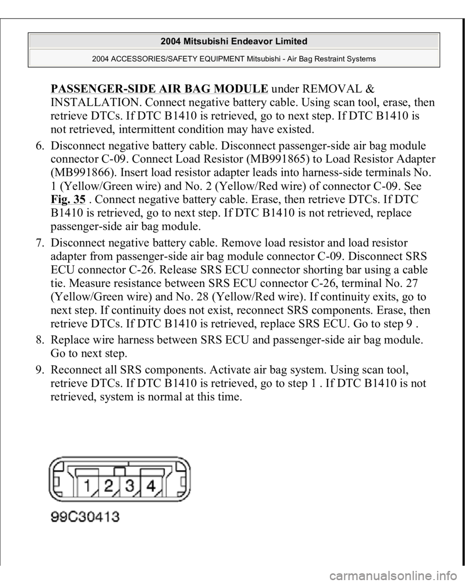
6. Disconnect negative battery cable. Disconnect passenger-side air bag module
connector C-09. Connect Load Resistor (MB991865) to Load Resistor Adapter
(MB991866). Insert load resistor adapter leads into harness-side terminals No.
1 (Yellow/Green wire) and No. 2 (Yellow/Red wire) of connector C-09. See
Fig. 35
. Connect negative battery cable. Erase, then retrieve DTCs. If DTC
B1410 is retrieved, go to next step. If DTC B1410 is not retrieved, replace
passenger-side air bag module.
7. Disconnect negative battery cable. Remove load resistor and load resistor
adapter from passenger-side air bag module connector C-09. Disconnect SRS
ECU connector C-26. Release SRS ECU connector shorting bar using a cable
tie. Measure resistance between SRS ECU connector C-26, terminal No. 27
(Yellow/Green wire) and No. 28 (Yellow/Red wire). If continuity exits, go to
next step. If continuity does not exist, reconnect SRS components. Erase, then
retrieve DTCs. If DTC B1410 is retrieved, replace SRS ECU. Go to step 9 .
8. Replace wire harness between SRS ECU and passenger-side air bag module.
Go to next step.
9. Reconnect all SRS components. Activate air bag system. Using scan tool,
retrieve DTCs. If DTC B1410 is retrieved, go to step 1 . If DTC B1410 is not
retrieved, system is normal at this time.
2004 Mitsubishi Endeavor Limited
2004 ACCESSORIES/SAFETY EQUIPMENT Mitsubishi - Air Bag Restraint Systems
Page 360 of 3870
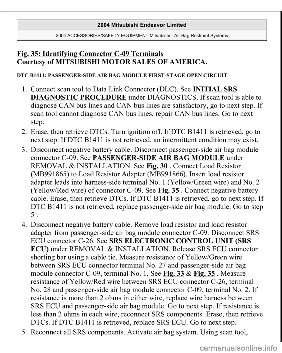
Fig. 35: Identifying Connector C
-09 Terminal
s
Courtesy of MITSUBISHI MOTOR SALES OF AMERICA.
DTC B1411: PASSENGER-SIDE AIR BAG MODULE FIRST-STAGE OPEN CIRCUIT 1. Connect scan tool to Data Link Connector (DLC). See INITIAL SRS
DIAGNOSTIC PROCEDURE
under DIAGNOSTICS. If scan tool is able to
diagnose CAN bus lines and CAN bus lines are satisfactory, go to next step. If
scan tool cannot diagnose CAN bus lines, repair CAN bus lines. Go to next
step.
2. Erase, then retrieve DTCs. Turn ignition off. If DTC B1411 is retrieved, go to
next step. If DTC B1411 is not retrieved, an intermittent condition may exist.
3. Disconnect negative battery cable. Disconnect passenger-side air bag module
connector C-09. See PASSENGER
-SIDE AIR BAG MODULE
under
REMOVAL & INSTALLATION. See Fig. 30
. Connect Load Resistor
(MB991865) to Load Resistor Adapter (MB991866). Insert load resistor
adapter leads into harness-side terminal No. 1 (Yellow/Green wire) and No. 2
(Yellow/Red wire) of connector C-09. See Fig. 35
. Connect negative battery
cable. Erase, then retrieve DTCs. If DTC B1411 is retrieved, go to next step. If
DTC B1411 is not retrieved, replace passenger-side air bag module. Go to step
5 .
4. Disconnect negative battery cable. Remove load resistor and load resistor
adapter from passenger-side air bag module connector C-09. Disconnect SRS
ECU connector C-26. See SRS ELECTRONIC CONTROL UNIT (SRS
ECU)
under REMOVAL & INSTALLATION. Release SRS ECU connector
shorting bar using a cable tie. Measure resistance of Yellow/Green wire
between SRS ECU connector terminal No. 27 and passenger-side air bag
module connector C-09, terminal No. 1. See Fig. 33
& Fig. 35
. Measure
resistance of Yellow/Red wire between SRS ECU connector C-26, terminal
No. 28 and passenger-side air bag module connector C-09, terminal No. 2. If
resistance is more than 2 ohms in either wire, replace wire harness between
SRS ECU and passenger-side air bag module. Go to next step. If resistance is
less than 2 ohms in each wire, reconnect SRS components. Erase, then retrieve
DTCs. If DTC B1411 is retrieved, replace SRS ECU. Go to next step.
5. Reconnect all SRS components. Activate air bag sys
tem. Using scan tool,
2004 Mitsubishi Endeavor Limited
2004 ACCESSORIES/SAFETY EQUIPMENT Mitsubishi - Air Bag Restraint Systems