set MITSUBISHI GALANT 1989 Service Repair Manual
[x] Cancel search | Manufacturer: MITSUBISHI, Model Year: 1989, Model line: GALANT, Model: MITSUBISHI GALANT 1989Pages: 1273, PDF Size: 37.62 MB
Page 1084 of 1273
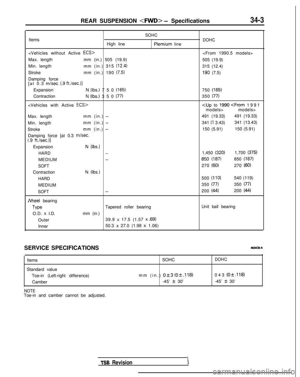
REAR SUSPENSION
SOHCItems
High linePlemium line
Max. length mm (in.) 505 (19.9)
Min. length mm (in.) 315
(12.4)
Stroke mm (in.) 190 (7.5)
Damping force
[at 0.3 m/set. (.9 ft.Isec.11
ExpansionN (Ibs.) 750 (165)
ContractionN (Ibs.) 350 (77)
Max. length mm (in.) -
Min. lengthmm (in.) -
Stroke mm (in.) -
Damping force [at 0.3 m/set.I.9 ft./sec.)l
ExpansionN (Ibs.)
HARD
-
MEDIUM-
SOFT
ContractionN (Ibs.)
HARD
MEDIUM
SOFT-
JVheel bearing Type
Tapered roller bearing
O.D.
x I.D. mm (in.)
Outer 39.9
x 17.5 (1.57 x .69)
Inner
50.3 x 27.0 (1.98 x
1.06)
DOHC
505 (19.9)
315 (12.4)
190 (7.5)
750
(165)
350 (77)
models> models>
491 (19.33) 491 (19.33)
341 (I
3.43) 341 (13.43)
150 (5.91) 150 (5.91)
1,450
(320)1,700 (375)
850 (187)850 (187)
270 (60)270 (60)
500 (110)540 (119)
350
(77)350 (77)
200 (44)200 (44)
Unit ball bearing
SERVICE SPECIFICATIONS Items
Standard value Toe-in (Left-right difference)Camber
NOTEToe-in and camber cannot be adjusted.
MWX-A
SOHCDOHC
mm (in.) 0+3 (0+.118)043 (O&.118)
-45’
2 30’ -45’ + 30’ TSB
RevisionI
Page 1086 of 1273
REAR SUSPENSION
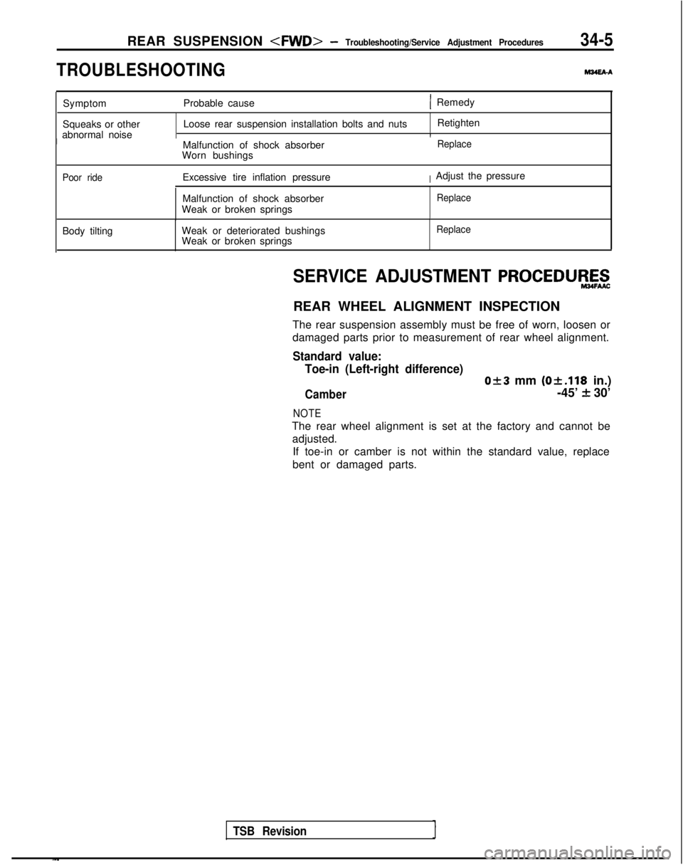
TROUBLESHOOTING
M34EAA
Symptom Probable cause( Remedy
Squeaks or other
abnormal noise Loose rear suspension installation bolts and nuts
Retighten
IMalfunction of shock absorber
Worn bushingsReplace
Poor ride
Excessive tire inflation pressureIAdjust the pressure
Malfunction of shock absorber
Weak or broken springs
Replace
Body tilting Weak or deteriorated bushings
Weak or broken springsReplace
TSB Revision
SERVICE ADJUSTMENT PROCEDUEZ$
REAR WHEEL ALIGNMENT INSPECTION
The rear suspension assembly must be free of worn, loosen or
damaged parts prior to measurement of rear wheel alignment.
Standard value: Toe-in (Left-right difference)
0+3 mm (Ok.118
in.)
Camber-45’ f 30’
NOTE
The rear wheel alignment is set at the factory and cannot be
adjusted. If toe-in or camber is not within the standard value, replace
bent or damaged parts.
Page 1090 of 1273
REAR SUSPENSION
Turn 180” or more antreturn360” or more.epeat 3
times of
TSB Revision1.
SERVICE POINTS OF INSTALLATIONMS4GDAS
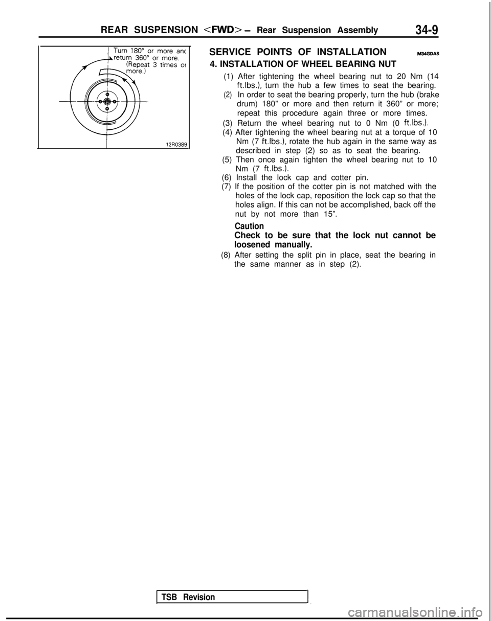
4. INSTALLATION OF WHEEL BEARING NUT
(1) After tightening the wheel bearing nut to 20 Nm (14 ft.lbs.),
turn the hub a few times to seat the bearing.
(2)In order to seat the bearing properly, turn the hub (brake
drum) 180” or more and then return it 360” or more;
repeat this procedure again three or more times.
(3) Return the wheel bearing nut to 0 Nm (0 ft.lbs.).
(4) After tightening the wheel bearing nut at a torque of 10 Nm (7
ftlbs.), rotate the hub again in the same way as
described in step (2) so as to seat the bearing.
(5) Then once again tighten the wheel bearing nut to 10 Nm (7 ft.lbs.).
(6) Install the lock cap and cotter pin.
(7) If the position of the cotter pin is not matched with the
holes of the lock cap, reposition the lock cap so that the
holes align. If this can not be accomplished, back off the
nut by not more than 15”.
Caution
Check to be sure that the lock nut cannot be
loosened manually.
(8) After setting the split pin in place, seat the bearing in the same manner as in step (2).
Page 1098 of 1273
REAR SUSPENSION
Lateral rodmounting bolt
1 Turn 180” or more ant1
TSB Revision
SERVICE POINTS OF INSTALLATIONMtOPDAH
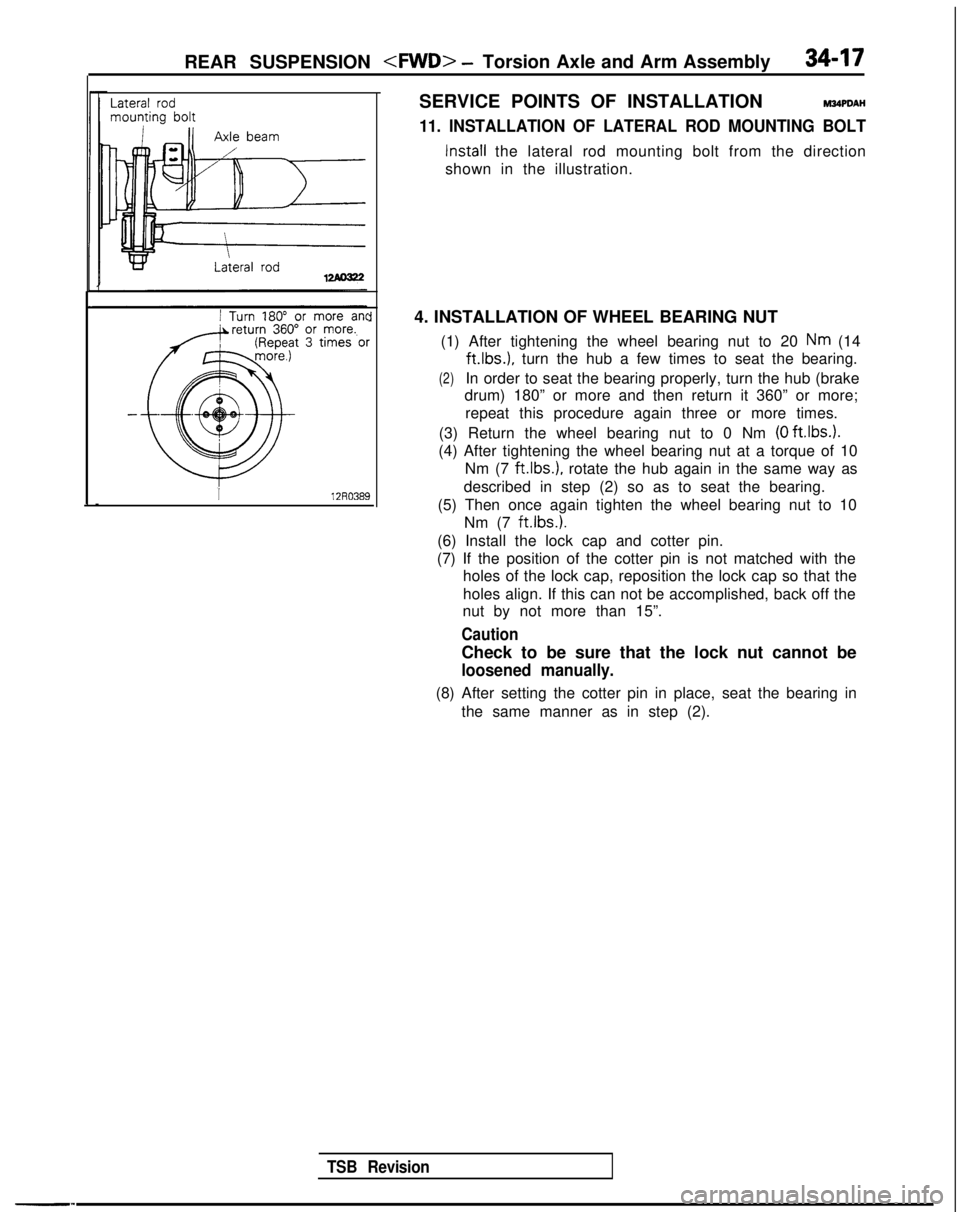
11. INSTALLATION OF LATERAL ROD MOUNTING BOLT
Install the lateral rod mounting bolt from the direction
shown in the illustration.
4. INSTALLATION OF WHEEL BEARING NUT (1) After tightening the wheel bearing nut to 20
Nm (14 ft.lbs.),
turn the hub a few times to seat the bearing.
(2)In order to seat the bearing properly, turn the hub (brake
drum) 180” or more and then return it 360” or more;
repeat this procedure again three or more times.
(3) Return the wheel bearing nut to 0 Nm
(0 ftlbs.).
(4) After tightening the wheel bearing nut at a torque of 10 Nm (7
ftlbs.), rotate the hub again in the same way as
described in step (2) so as to seat the bearing.
(5) Then once again tighten the wheel bearing nut to 10 Nm (7 ft.lbs.).
(6) Install the lock cap and cotter pin.
(7) If the position of the cotter pin is not matched with the holes of the lock cap, reposition the lock cap so that the
holes align. If this can not be accomplished, back off the
nut by not more than 15”.
Caution
Check to be sure that the lock nut cannot be
loosened manually.
(8) After setting the cotter pin in place, seat the bearing in
the same manner as in step (2).
Page 1114 of 1273
Pressure fittingRemoval
REAR SUSPENSION
M34TCAA
0 Check trailing arm for cracks and deformation.
l Check bushing for cracks, deterioration and wear.
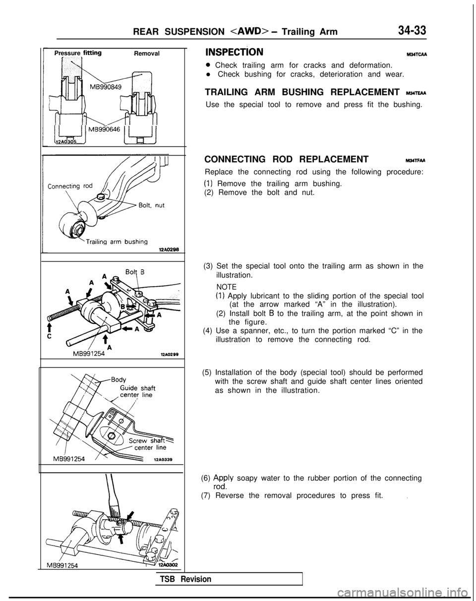
TRAILING ARM BUSHING REPLACEMENT
wm
Use the special tool to remove and press fit the bushing.
i Le$ iMBggo646w12AO305
-‘Trailing arm
bushing12AO296
Bolt B
MB991254
12AO299
Body
Guide
shaftcenter line.\/ ’
MB991254
12A0339
MB991
254-
CONNECTING ROD REPLACEMENTMwrFAA
Replace the connecting rod using the following procedure:
(1) Remove the trailing arm bushing.
(2) Remove the bolt and nut.
(3) Set the special tool onto the trailing arm as shown in the illustration.
NOTE
(1) Apply lubricant to the sliding portion of the special tool(at the arrow marked “A” in the illustration).
(2) Install bolt
B to the trailing arm, at the point shown in
the figure.
(4) Use a spanner, etc., to turn the portion marked “C” in the
illustration to remove the connecting rod.
(5) Installation of the body (special tool) should be performed with the screw shaft and guide shaft center lines oriented
as shown in the illustration.
(6)
zdyly soapy water to the rubber portion of the connecting
(7) Reverse the removal procedures to press fit.
I
TSB Revision
Page 1139 of 1273
35-18SERVICE BRAKES - Anti-lock Braking System Troubleshooting
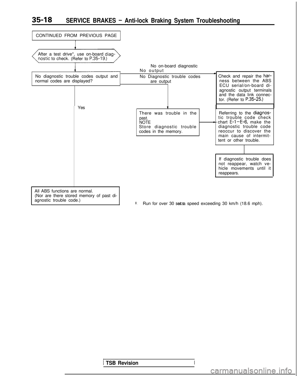
CONTINUED FROM PREVIOUS PAGEAfter a test drive*, use on-board diag-
ostic
to check.
(Refer to
P.35-19.)
No diagnostic trouble codes output and
normal codes are displayed? No on-board diagnostic
No outpu
t
No Diagnostic trouble codes are output
D Check and repair the har-
ness between the ABS
ECU serial/on-board di-
agnostic output terminals
and the data link connec-
tor. (Refer to
P.35-25.)
Yes
All ABS functions are normal. (Nor are there stored memory of past di-
agnostic trouble code.)t
There was trouble in the
past.
NOTE
Store diagnostic trouble
codes in the memory. Referring to the
diagnos-tic trouble code checkc chart E-l-E-6, make the
diagnostic trouble code
reoccur to discover the
main cause of intermit-
tent or other trouble.
If diagnostic trouble does
not reappear, watch ve-
hicle movements until it
reappears.
l :Run for over 30 sets. at a speed exceeding 30 km/h (18.6 mph).
1 TSB RevisionI
Page 1157 of 1273
35-36SERVICE BRAKES -Anti-lock Braking System Troubleshooting
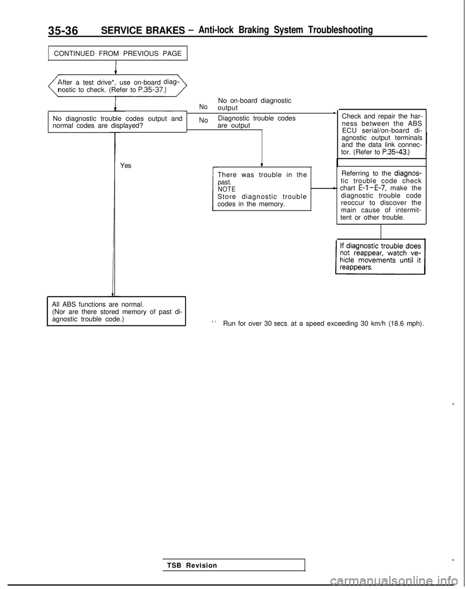
CONTINUED FROM PREVIOUS PAGE
I
fter a test drive*, use on-board
diag-
nostic to check. (Refer to P.35-37.)
No diagnostic trouble codes output and
normal codes are displayed?
NoNo on-board diagnostic
output l
NoDiagnostic trouble codes
are output
Yes Check and repair the har-
ness between the ABS
ECU serial/on-board di-
agnostic output terminals
and the data link connec-
tor. (Refer to
P.35-43.)
t
There was trouble in thepast.NOTEStore diagnostic trouble
codes in the memory. Referring to the diagnos-
tic trouble code check
- chart E-l-E-7, make the
diagnostic trouble code
reoccur to discover the
main cause of intermit-
tent or other trouble.
c
TSB Revision
All ABS functions are normal.
(Nor are there stored memory of past di-
agnostic trouble code.)
l .8Run for over 30 sets. at a speed exceeding 30 km/h (18.6 mph).
Page 1179 of 1273
35-58SERVICE BRAKES - Service Adjustment Procedures
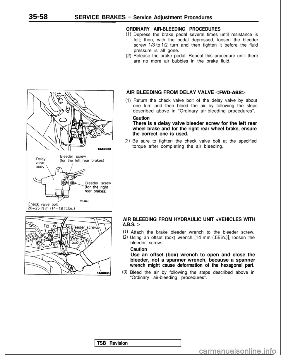
14*ooat
Delay
valve Bleeder screw
(for the left rear brakes)i
Bleeder screw
I.LOO.1lheck valve bolt20-25 Nm (14-18 ft.lbs.)
ORDINARY AIR-BLEEDING PROCEDURES
(1) Depress the brake pedal several times until resistance is
felt; then, with the pedal depressed, loosen the bleederscrew
113 to l/2 turn and then tighten it before the fluid
pressure is all gone.
(2) Release the brake pedal. Repeat this procedure until there
are no more air bubbles in the brake fluid.
AIR BLEEDING FROM DELAY VALVE
4WD-ABS>
(1) Return the check valve bolt of the delay valve by about one turn and then bleed the air by following the steps
described above in “Ordinary air-bleeding procedures”.
Caution
There is a delay valve bleeder screw for the left rear
wheel brake and for the right rear wheel brake, ensure
the correct one is used.
(2) Be sure to tighten the check valve bolt at the specified
torque after completing the air bleeding.
AIR BLEEDING FROM HYDRAULIC UNIT
(1) Attach the brake bleeder wrench to the bleeder screw.
(2) Using an offset (box) wrench 114 mm (55 in.)], loosen the
bleeder screw.
Caution
Use an offset (box) wrench to open and close the
bleeder, not a spanner wrench, because a spanner
wrench might cause deformation of the hexagonal part.
(3) Bleed the air by following the steps described above in “Ordinary air-bleeding procedures”.
TSB Revision
Page 1184 of 1273
SERVICE BRAKES - Service Adjustment Procedures35-63
(4) Calculate the drag torque of the disc brake (difference
between measured values in 3 and 4).
Standard value: 70 N (15.4 Ibs.) or less
10. If the disc brake drag force exceeds the standard value,
disassemble piston and clean the piston. Check for corro-
sion or worn piston seal, and check the sliding condition of
the lock pin and guide pin.
Front Disc Brake Rotor Inspection
CAUTION
When servicing disc brakes, it is necessary to exercise caution to keep \
the disc brakes within the allowable service values in order to maintain normal brake operation.
Before re-finishing or re-processing the brake disc surface, the followi\
ng conditions should be checked.
Inspection items
Scratches, rust, saturated lining materialsand wear
Run-out or drift
Change in thickness (parallelism) Inset or warping (flatness) Remarks
lIf the vehicle is not driven for a certain period, the sections of the d\
iscs
that are not in contact with lining will become rusty, causing noise and\
shuddering.
lIf grooves resulting from excessive disc wear and scratches are not re-
moved prior to installing a new pad assembly, there will momentarily
be inappropriate contact between the disc and the lining (pad).
Excessive run-out or drift of the discs will increase the pedal depressi\
on
resistance due to piston knock-back.
If the thickness of the disc changes, this will cause pedal pulsation, s\
hud-dering and surging.
Overheating and improper handling while servicing will cause inset orwarping.
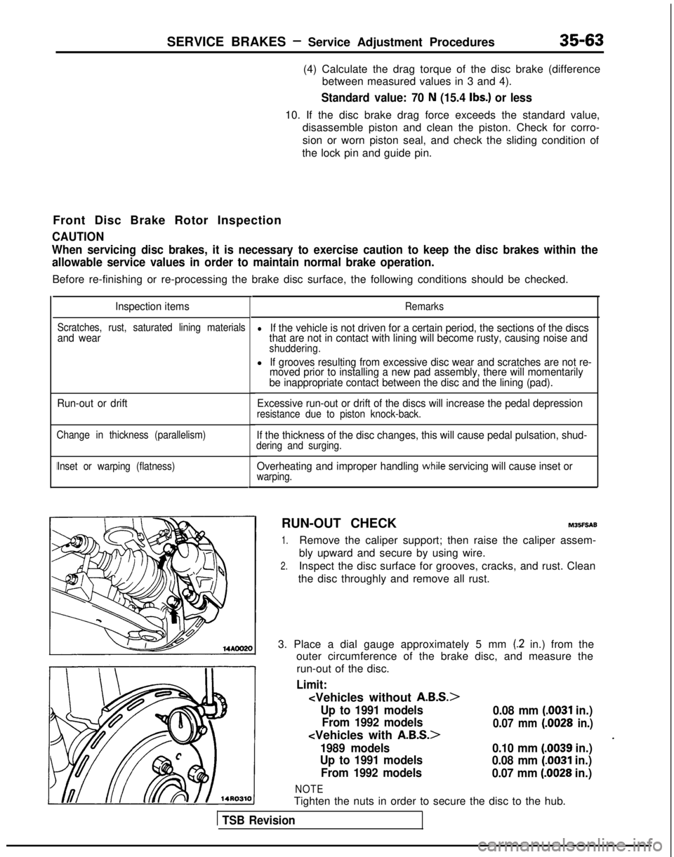
RUN-OUT CHECKM35F5AB
1.Remove the caliper support; then raise the caliper assem-
bly upward and secure by using wire.
2.Inspect the disc surface for grooves, cracks, and rust. Clean
the disc throughly and remove all rust.
3. Place a dial gauge approximately 5 mm
(.2 in.) from the
outer circumference of the brake disc, and measure the
run-out of the disc.
Limit:
Up to 1991 models
0.08 mm (.0031 in.)
From 1992 models
0.07 mm (.0028 in.)
*1989 models
0.10 mm (.0039 in.)
Up to 1991 models 0.08 mm
(0031 in.)
From 1992 models 0.07 mm
(.0028 in.)
NOTE
Tighten the nuts in order to secure the disc to the hub.
1 TSB Revision
Page 1188 of 1273
SERVICE BRAKES - Service Adjustment Procedures35-67
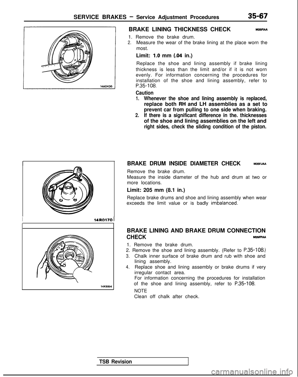
BRAKE LINING THICKNESS CHECKM35FlAA
1. Remove the brake drum.
2.Measure the wear of the brake lining at the place worn the
most.
Limit:
1.0 mm (.04 in.)
Replace the shoe and lining assembly if brake lining
thickness is less than the limit and/or if it is not worn
evenly. For information concerning the procedures for installation of the shoe and lining assembly, refer to
P.35-108.
Caution
1.Whenever the shoe and lining assembly is replaced,
replace both RH and LH assemblies as a set to
prevent car from pulling to one side when braking.
2.If there is a significant difference in the. thicknesses
of the shoe and lining assemblies on the left and
right sides, check the sliding condition of the piston.
BRAKE DRUM INSIDE DIAMETER CHECK
Remove the brake drum.
M3!5FJAA
Measure the inside diameter of the hub and drum at two or
more locations.
Limit: 205 mm (8.1 in.) Replace brake drums and shoe and lining assembly when wear
exceeds the limit value or is badly
imbalanced.
TSB Revision
IlAR0170 1
14K664
BRAKE LINING AND BRAKE DRUM CONNECTION
CHECKM35FFAA
1. Remove the brake drum.
2. Remove the shoe and lining assembly. (Refer to
P.35-108.)
3.Chalk inner surface of brake drum and rub with shoe and
lining assembly.
4.Replace shoe and lining assembly or brake drums if very
irregular contact area.
For information concerning the procedures for installation
of the shoe and lining assembly, refer to
P.35-108.
NOTE
Clean off chalk after check.