set MITSUBISHI GALANT 1989 Service Repair Manual
[x] Cancel search | Manufacturer: MITSUBISHI, Model Year: 1989, Model line: GALANT, Model: MITSUBISHI GALANT 1989Pages: 1273, PDF Size: 37.62 MB
Page 898 of 1273
27-38REAR AXLE
@ If the differential gear backlash exceeds the limit,
adjust the backlash by installing thicker side gear
spacers. @ Measure the differential gear backlash once again,
and confirm that it is within the limit.
NOTE
(1) After adjustment, check that the backlash is the
less than the limit and differential gear rotates
smoothly.
(2) When adjustment is impossible, replace the side
gear and the pinion gear as a set.
Spring pin
‘\ /
Drive gear TNyh fl
l~1/p(---\y-jj !5Lz+ /
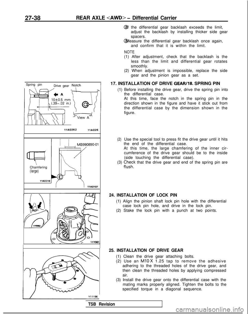
17. INSTALLATION OF DRIVE GEAR/18. SPRING PIN
(1) Before installing the drive gear, drive the spring pin into the differential case.
At this time, face the notch in the spring pin in the
direction shown in the figure and have it stick out from
the differential case by the dimension shown in the
figure.
I I II II\ \\ II
llAO262llA026
1 / / MB990890-01
Chamfering
(large) llA0316
llA0101
(2)Use the special tool to press fit the drive gear until it hits
the end of the differential case.
At this time, the large chamfering of the inner cir-
cumference of the drive gear should be to the inside
(side touching the differential case).
(3)
ii,“;k that the drive gear and end of the spring pin are
24. INSTALLATION OF LOCK PIN
(1) Align the pinion shaft lock pin hole with the differential case lock pin hole, and drive in the lock pin.
(2) Stake the lock pin with a punch at two points.
25. INSTALLATION OF DRIVE GEAR
(1) Clean the drive gear attaching bolts.
(2) Use an
Ml0 X 1.25 tap to remove the adhesive
adhering to the threaded holes of the drive gear, and
then clean the threaded holes by applying compressed
air.
(3) Install the drive gear onto the differential case with the mating marks properly aligned. Tighten the bolts to the
specified torque in a diagonal sequence.
TSB Revision
Page 901 of 1273
31-2WHEEL AND TIRE - Specifications
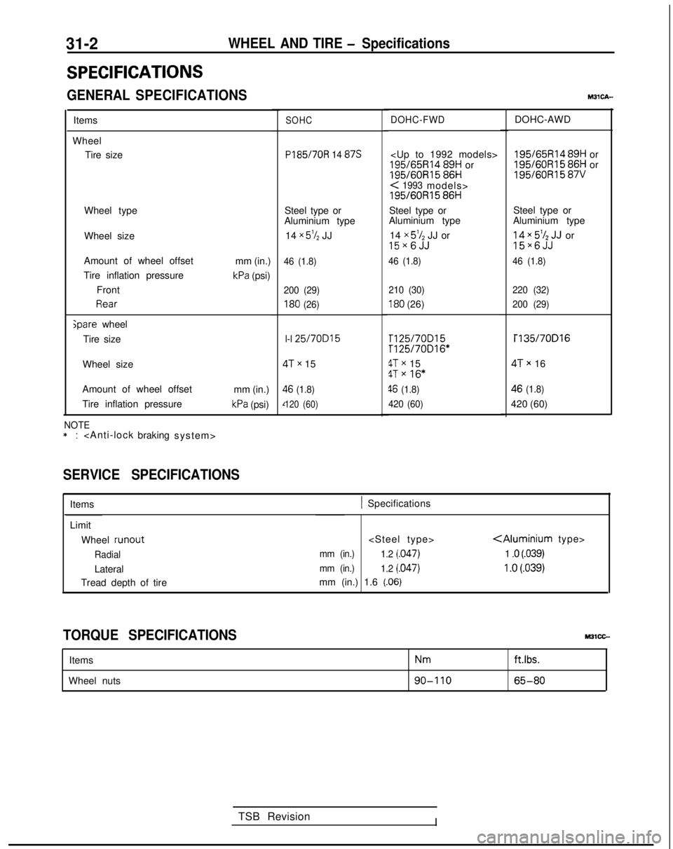
SPECIFICATIONS
GENERAL SPECIFICATIONS
Items
Wheel Tire size
Wheel type
Wheel size
Amount of wheel offset
Tire inflation pressure Front
Rear ;pare
wheel
Tire size mm (in.)
kPa (psi)
Wheel size
Amount of wheel offset
Tire inflation pressure mm (in.)
kPa (psi)
NOTE*:
SERVICE SPECIFICATIONS
SOHC PI
85/7OR 14 87s
Steel type or
Aluminium type
14
x 5% JJ
46 (1.8)
200 (29)
180 (26)
l-l 25/70D15
ITx 15
$6 (1.8)
120 (60)
TSB Revision
I
DOHC-FWD
86H
< 1993models>
195/60R15
86H
Steel type or
Aluminium type
14
x 5’/2 JJ or15~6JJ
46 (1.8)
210 (30)
180 (26)
rl25/70D15Tl25/70016*
4Tx 154Tx 16*
46 (1.8)
420 (60)
DOHC-AWD 195/65R14
89H or 195/60R15
86H or 195/60R15
87V
Steel type or
Aluminium type ; g
x ;‘$JJJ
orX
46 (1.8)
220 (32)
200 (29) T135/70D16
!Tx 16
$6 (1.8)
420 (60)
M3lcA--
Items1 Specifications
Limit Wheel runout
Radial
Lateral
Tread depth of tire
mm (in.)
1.2 j.047)
mm (in.)1.2 (.047)
mm (in.) 1.6 (.06)
1 .o (.039)
1 .o (.039)
TORQUE SPECIFICATIONS
Items
Wheel nutsNm
90-I 10
ft.lbs.
65-80
Page 908 of 1273
POWER PLANT MOUNT - Specifications/Special Tool32-3
Items
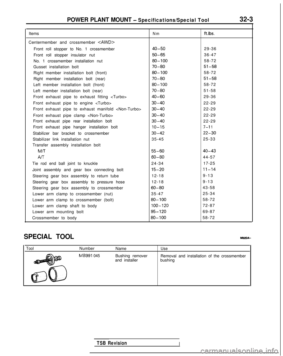
Centermember and crossmember
Front roll stopper to No. 1 crossmember
Front roll stopper insulator nut
No. 1 crossmember installation nut
Gusset installation bolt
Right member installation bolt (front)
Right member installation bolt (rear)
Left member installation bolt (front)
Left member installation bolt (rear)
Front exhaust pipe to exhaust fitting
Front exhaust pipe to engine
Front exhaust pipe to exhaust manifold
Front exhaust pipe clamp
Front exhaust pipe rear installation bolt
Front exhaust pipe hanger installation bolt
Stabilizer bar bracket to crossmember
Stabilizer link installation nut
Transfer assembly installation bolt MIT
Al-r
Tie rod end ball joint to knuckle
Joint assembly and gear box connecting bolt
Steering gear box assembly to return tube
Steering gear box assembly to pressure hose
Steering gear box assembly to crossmember Lower arm clamp to crossmember (nut)
Lower arm clamp to crossmember (bolt)
Lower arm clamp shaft to body
Lower arm mounting bolt
Crossmember to body
Nmftlbs.
40-5029-36
50-6536-47
80-10058-72
70-8051-58
80-10058-72
70-8051-58
80-10058-72
70-8051-58
40-6029-36
30-4022-29
30-4022-29
30-4022-29
30-4022-29
10-157-l 1
30-4222-30
35-45 25-33
55-6040-43
60-8044-57
24-34 17-25
15-2011-14
12-189-1
3
12-18 9-13
60-8043-58
35-47 25-34
80-10058-72
100-12072-87
95-12069-87
80-10058-72
SPECIAL TOOL
ToolNumber
MB991
045
Name
Bushing remover
and installerUse
Removal and installation of the crossmember
bushing
TSB RevisionI
Page 917 of 1273
32-12POWER PLANT MOUNT -Centermember and Crossmember
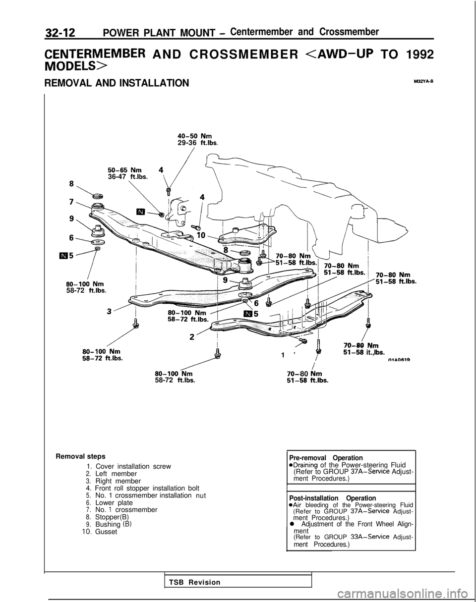
C&Et;;rSM>EMBER AND CROSSMEMBER
40-50 Nm29-36 ft.lbs.
50-65 Nm36-47 ft.lbs.80-100
Nm58-72 ftlbs.
80-100
Nm58-72 ft.lbs.
1
’
--
--_ii-58 it.,tTlAO619I 70-r
80 km51-58klbs.
Removal steps
1. Cover installation screw
2.Left member3.Right member
4. Front roll stopper installation bolt
5.No. 1 crossmember installation
nut6.Lower plate7.No. 1 crossmember8.Stopper(B)9.Bushing (B)10.Gusset
Pre-removal OperationeDraining of the Power-steering Fluid
(Refer to GROUP 37A-Service
Adjust-
ment Procedures.)
Post-installation Operation@Air bleeding of the Power-steering Fluid
(Refer to GROUP 37A-Service Adjust-ment Procedures.)l Adjustment of the Front Wheel Align-
ment
(Refer to GROUP 33A-Service Adjust-ment Procedures.)
TSB Revision
Page 923 of 1273
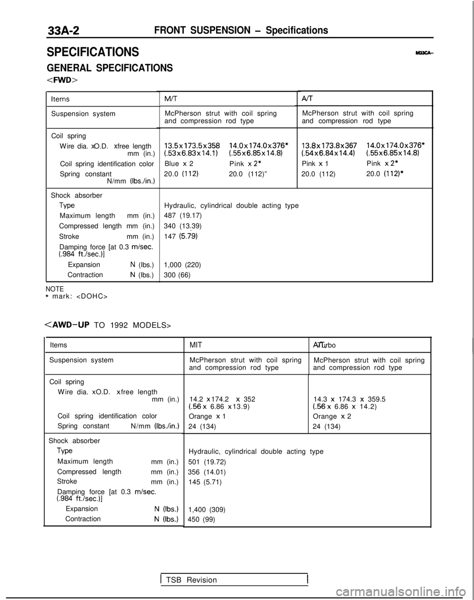
33A-2FRONT SUSPENSION - Specifications
SPECIFICATIONS
GENERAL SPECIFICATIONS
Items
Suspension system
Coil springW
ire dia. x O.D. x free length
mm (in.)
Coil spring identification color
Spring constant N/mm (IbsAn.)
Shock absorber Type
Maximum length mm (in.)
Compressed length mm (in.)
Stroke mm (in.)
Damping force [at 0.3 misec.
t.984 ft./sec.)l
ExpansionN (Ibs.)
Contraction
N (Ibs.) MIT Al-r
McPherson strut with coil spring McPherson strut with coil spring
and compression rod type and compression rod type
13.5x173.5x358 14.0x174.0x376*(.53x6.83x14.1) (55x6.85x14.8)
Blue x 2
Pink x
2”
20.0 (112)20.0 (112)”
13.8x173.8x367 14.0x174.0x376*(54x6.84x14.4) (.55x6.85x14.8)
Pink x 1 Pink x
2”
20.0 (112) 20.0 (112)*
Hydraulic, cylindrical double acting type
487 (19.17)
340 (13.39) 147
(5.j9)
1,000 (220)
300 (66)
NOTE* mark:
Items
Suspension system
Coil spring W
ire dia. x O.D. x free length
mm (in.)
Coil spring identification color
Spring constant N/mm
(Ibs./in.)
Shock absorberType
Maximum length mm (in.)
Compressed length mm (in.)
Stroke mm (in.)
Damping force [at 0.3
m/set.t.984 ft./set.)]
ExpansionN (Ibs.)
ContractionN (Ibs.)
MIT A/T, Turbo
McPherson strut with coil spring McPherson strut with coil spring
and compression rod type and compression rod type
14.2 x 174.2 x
352(56
x
6.86 x 13.9)
Orange x
1
24 (134) 14.3 x
174.3 x
359.5(56 x
6.86 x
14.2)
Orange x
2
24 (134)
Hydraulic, cylindrical double acting type
501 (19.72)
356 (14.01) 145 (5.71)
1,400 (309)
450 (99)
1 TSB Revision
Page 924 of 1273
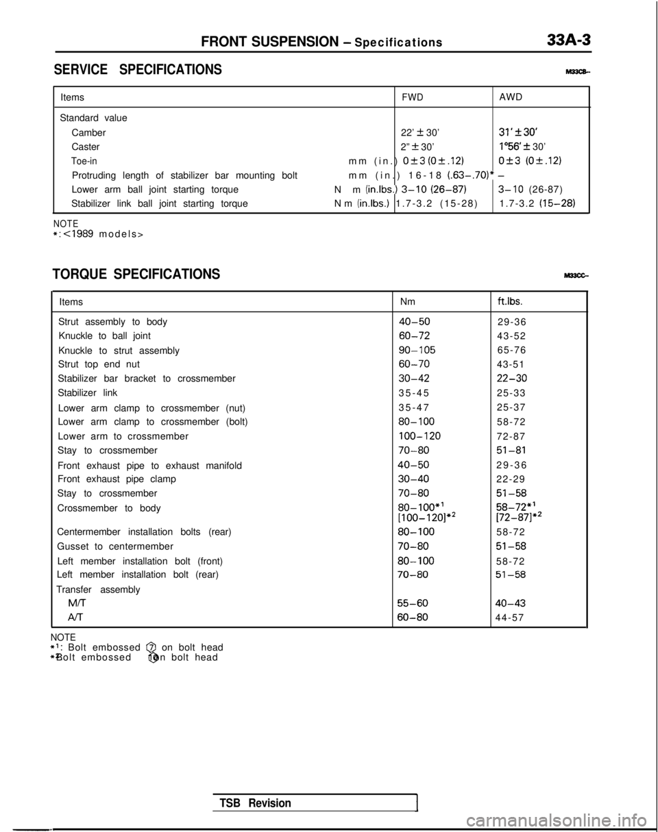
FRONT SUSPENSION - Specifications33A-3
SERVICE SPECIFICATIONSM33cB-
Items
Standard value Camber
Caster
Toe-in
Protruding length of stabilizer bar mounting bolt
Lower arm ball joint starting torque
Stabilizer link ball joint starting torque
NOTE*:
FWDAWD
22’
k 30’31’f30’
2” + 30’lo56 f 30’
mm (in.)
Ok3 (Of.12)0+3 (0+.12)
mm (in.) 16-18 (.63-.70)* -
Nm (in.lbs.1 3-10 (26-87)3- 10 (26-87)
Nm (in.lbs.)
1.7-3.2 (15-28) 1.7-3.2
(15-28)
TORQUE SPECIFICATIONS
Items
Strut assembly to body Knuckle to ball joint
Knuckle to strut assembly
Strut top end nut
Stabilizer bar bracket to crossmember
Stabilizer link
Lower arm clamp to crossmember (nut)
Lower arm clamp to crossmember (bolt)
Lower arm to crossmember
Stay to crossmember
Front exhaust pipe to exhaust manifold
Front exhaust pipe clamp
Stay to crossmember
Crossmember to body
Centermember installation bolts (rear)
Gusset to centermember Left member installation bolt (front)
Left member installation bolt (rear)
Transfer assembly M/T
Al-r Nmft.lbs.
40-5029-36
60-7243-52
go-10565-76
60-7043-51
30-4222-30
35-4
5
25-33
35-47 25-37
80- 10058-72
100-12072-87
70-8051-81
40-5029-3
6
30-4022-29
70-8051-58
80-loo*’58-72”’[100-120]*2[72-871”’
80-10058-72
70-8051-58
80-10058-72
70-8051-58
55-6040-43
60-8044-57
TSB Revision
NOTE*I: Bolt embossed @I on bolt head
*2: Bolt embossed @ on bolt head
Page 926 of 1273
FRONT SUSPENSION - Service Adiustment Procedures33A-5
eI
-a,
-
\ ~,I 1, 1
FY
TSB Revision
SERVICE ADJUSTMENT PROCEDURES
FRONT WHEEL ALIGNMENTM33FBAQ
NOTE
The front suspension assembly must be free of worn, loose or
damaged parts prior to measurement of front wheel align- ments. Measure wheel alignment by using the tool.
CAMBER AND CASTER
Standard value:
Camber22’ f 30’ 31’& 30
Caster2”f301”56’rtr30
Camber and caster are pre-set at the factory and cannot be
adjusted.
NOTE
If camber and caster are not within specifications, replace bent
or damaged parts.
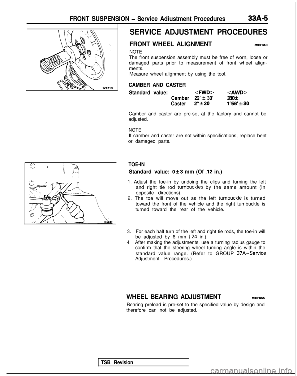
TOE-IN
Standard value: Ok3 mm (Of .12 in.)
1. Adjust the toe-in by undoing the clips and turning the left and right tie rod turnbuckles
by the same amount (in
opposite directions).
2. The toe will move out as the left turnbuckle
is turned
toward the front of the vehicle and the right turnbuckle is
turned toward the rear of the vehicle.
3.For each half turn of the left and right tie rods, the toe-in will
be adjusted by 6 mm
(24 in.).
4.After making the adjustments, use a turning radius gauge to confirm that the steering wheel turning angle is within the
standard value range. (Refer to GROUP
37A-Service
Adjustment Procedures.)
WHEEL BEARING ADJUSTMENTM?SCAA
Bearing preload is pre-set to the specified value by design and
therefore can not be adjusted.
Page 938 of 1273
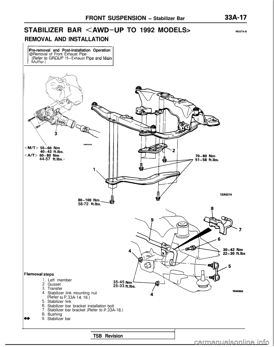
FRONT SUSPENSION - Stabilizer Bar
STABILIZER BAR
REMOVAL AND INSTALLATION
Pre-removal and Post-installation Operation@Removal of Front Exhaust Pipe(Refer to GROUP 15-Exhaust Pipe and Main
\:M/T> 55-60 Nm40-43 ftlbs.
:A/T>
60-80 Nm44-57 ft.lbs. *
Iemoval steps
::3.4.
::
i:9.
Left member
Gusset
Transfer
Stabilizer link mounting nut
(Refer to P.33A-14, 16.)
Stabilizer link
Stabilizer bar bracket installation
Stabilizer bar bracket (Refer to
PBushing
Stabilizer bar 80-100
Nm58-72 ftlbs.
35-45
25-33
bolt
.33A-16.)
70-80 Nm51-58 ftlbs. MBJTA-B
-42
Nmiik.30 ft.lbs
TSB Revision
Page 941 of 1273
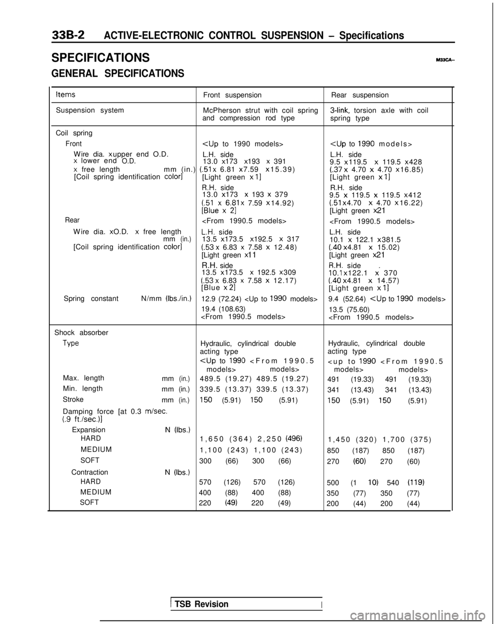
33B-2ACTIVE-ELECTRONIC CONTROL SUSPENSION - Specifications
SPECIFICATIONSM33CA-
GENERAL SPECIFICATIONS
ItemsFront suspensionRear suspension
Suspension system McPherson strut with coil spring 3-link,
torsion axle with coil
and compression rod type spring type
Coil spring
Front
Wire dia. x upper end O.D.
L.H. side L.H. side
x lower endO.D.13.0 x 173 x 193 x 391
9.5 x 119.5 x
119.5 x 428x free length
mm (in.) (51
x 6.81 x 7.59 x 15.39)(.37
x
4.70 x 4.70 x 16.85)
[Coil spring identification color1[Light green x II[Light green x
11
R.H. side R.H. side
13.0 x 173 x 193 x 379
9.5 x
119.5 x
119.5 x 412
;;lexx6$1 x 7.59
x 14.92) (51
x 4.70 x
4.70 x 16.22)U[Light green
x 21
Rear
W
ire dia. x O.D.
x free lengthL.H. side
L.H. side
mm(in.)13.5 x 173.5 x 192.5 X 317
10.1 x
122.1 x 381.5
[Coil spring identification color]
(.53 x 6.83 x 7.58
x
12.48)(.40 x 4.81 x
15.02)
[Light green x 11
[Light green x 21
R.H. side
R.H. side
13.5 x 173.5 x 192.5 x 30910.1
x 122.1 x. 370(53 x 6.83 x 7.58
x
12.17)(.40 x 4.81 x
14.57)
[Blue x 21[Light green
x
11
Spring constant N/mm (Ibs./in.)12.9 (72.24)
19.4 (108.63) 13.5 (75.60)
Shock absorber Type
Hydraulic, cylindrical double
Hydraulic, cylindrical double
acting type acting type
models> models>
models> models>
Max. length mm
(in.)489.5 (19.27) 489.5 (19.27) 491 (19.33) 491 (19.33)
Min. length mm
(in.)339.5 (13.37) 339.5 (13.37) 341 (13.43) 341 (13.43)
Stroke mm
(in.)150 (5.91) 150 (5.91)150 (5.91) 150 (5.91)
Damping force [at 0.3
m/set.(.9 ft./sec.)l
ExpansionN (Ibs.)
HARD
1,650 (364) 2,250 (496)1,450 (320) 1,700 (375
)
MEDIUM 1,100 (243) 1,100 (243) 850 (187) 850 (187)
SOFT300 (66) 300 (66) 270 (60) 270 (60)
Contraction
N (Ibs.)
HARD
570 (126) 570 (126) 500 (1 IO) 540 (119)
MEDIUM400 (88) 400 (88) 350 (77) 350 (77)
SOFT220 (49) 220 (49)200 (44) 200 (44)
1 TSB RevisionI
Page 942 of 1273
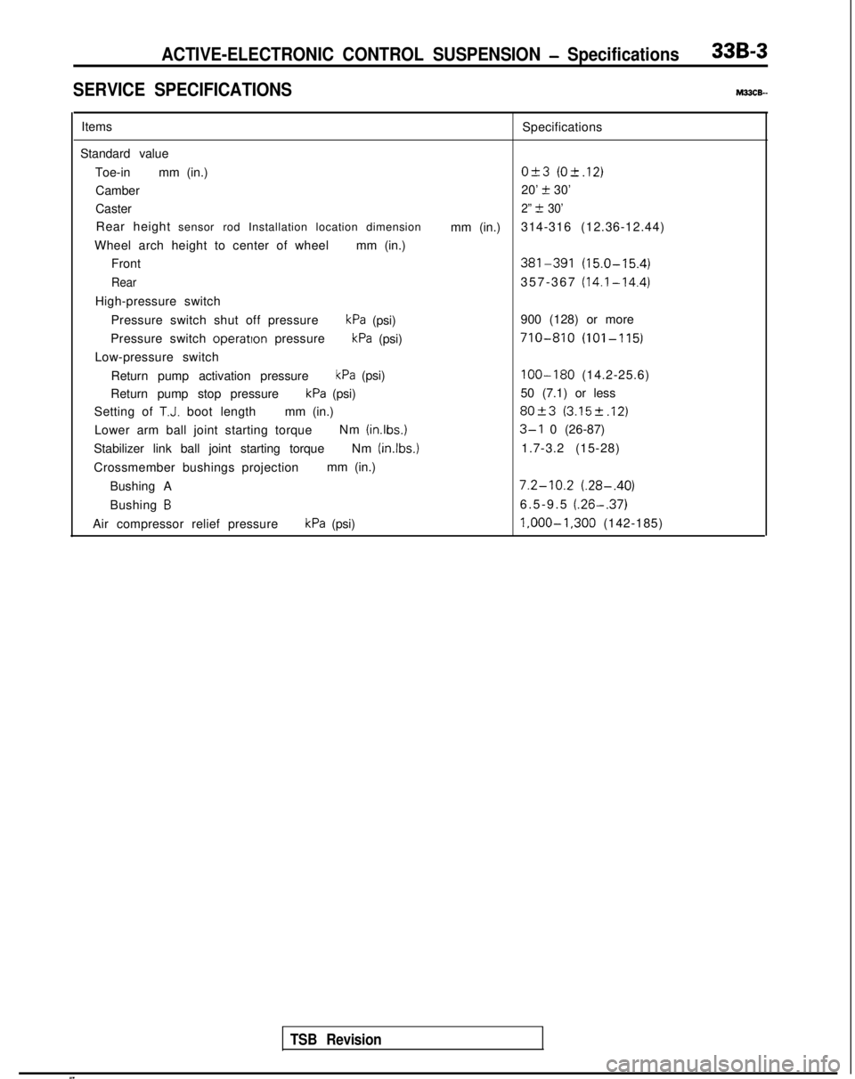
ACTIVE-ELECTRONIC CONTROL SUSPENSION - Specifications33B-3
SERVICE SPECIFICATIONSM33cE-
ItemsSpecifications
Standard value Toe-in mm (in.)
O&3 (O-t.12)
Camber 20’ t 30’
Caster
2” t 30’
Rear height sensor rod Installation location dimension
mm (in.)314-316 (12.36-12.44)
Wheel arch height to center of wheel mm (in.)
Front
381-391 (15.0-15.4)
Rear357-367 (14.1-14.4)
High-pressure switch
Pressure switch shut off pressure
kPa (psi) 900 (128) or more
Pressure switch operatton
pressure
kPa (psi)710-810 (101-115)
Low-pressure switch
Return pump activation pressure
kPa (psi)100-180 (14.2-25.6)
Return pump stop pressure
kPa (psi) 50 (7.1) or less
Setting of
T.J. boot length mm (in.)80+3 (3.152.12)
Lower arm ball joint starting torque Nm (inlbs.)3-l 0 (26-87)
Stabilizer link ball joint starting torque Nm (in.lbs.)
1.7-3.2 (15-28)
Crossmember bushings projection mm (in.)
Bushing A
7.2-10.2 (.28-.40)
Bushing B6.5-9.5 (.26-.37)
Air compressor relief pressurekPa (psi) l,OOO-1,300
(142-185)
TSB Revision