set MITSUBISHI GALANT 1989 Service Repair Manual
[x] Cancel search | Manufacturer: MITSUBISHI, Model Year: 1989, Model line: GALANT, Model: MITSUBISHI GALANT 1989Pages: 1273, PDF Size: 37.62 MB
Page 956 of 1273
![MITSUBISHI GALANT 1989 Service Repair Manual ACTIVE-ELECTRONIC CONTROL SUSPENSION - Troubleshooting 33B-17
CHECKING ACCORDING TO CHARTS CLASSIFIED BY THE MALFUNCTION SYMPTOM
[A] DIAGNOSTIC TROUBLE CODE NO.54
No
Yes
b Excessive vehicle-height ad-](/img/19/57312/w960_57312-955.png "MITSUBISHI GALANT 1989 Service Repair Manual ACTIVE-ELECTRONIC CONTROL SUSPENSION - Troubleshooting 33B-17
CHECKING ACCORDING TO CHARTS CLASSIFIED BY THE MALFUNCTION SYMPTOM
[A] DIAGNOSTIC TROUBLE CODE NO.54
No
Yes
b Excessive vehicle-height ad-")
ACTIVE-ELECTRONIC CONTROL SUSPENSION - Troubleshooting 33B-17
CHECKING ACCORDING TO CHARTS CLASSIFIED BY THE MALFUNCTION SYMPTOM
[A] DIAGNOSTIC TROUBLE CODE NO.54
No
Yes
b Excessive vehicle-height ad-justment
(overload) overload). time (due to -Unload the vehicle and turn* the ignition key to OFF; then
restart the engine and check
whether or not the system
functions normally.
Is the installation position of Nothe height sensor correct?
Yes Improper setting of the heightc sensor, or malfunction of the
height sensor. l Correct the installationcposition of the height sen-
sor, or adjust the vehicle
-height sensor rod.
l Check the height sensor. Refer to troubleshooting
hints [IO] and
[ll]classified by circuit.
Are the front strut and rear
NoMalfunction of the rolling
shock absorber unit air spr-* diaphragm.
Repair the rolling diaphragm,
or replace the shock absorber
ings in normal condition?Lunit.
(become folded)
Yes
Is the sound of operation
NoThe solenoid valves remain
heard from each solenoid closed, or there is air leakage
valve necessary for th
e
’ due to a malfunction of the
vehicle-height adjustment? valve seat.
Yes
Is the air pressure in the
vehicle-height adjustment
Nopressure line 950 kPa (135
psi) or higher?
I
Yes Damaged or disconnected
wiring of the high-pressure
switch, or incorrect vehicle
-height adjustment pressureline.
l Check the high-pressure switch circuit.
* Refer to troubleshooting hint [5] classified by circuit.
l Correct the clogging pro-
blem, or replace the air
tube.
Control unit malfunction.
[B] DIAGNOSTIC TROUBLE CODE NO.55
- No
Does the compressor func-
tion normally?
Yes Replace the control unit.c l Power is not supplied to
the compressor.Refer to troubleshooting
hint
[18] classified by cir-
cuit.
0 Improper compressor com- pression.
Is the air pressure in the
Novehicle-height adjustment
pressure line 760 kPa (108psi) or lower? High-pressure
switch
isRefer to troubleshooting hint
shorted____* [5] classified by circuit.
Yes Air leakage.
TSB RevisionI
Page 958 of 1273
ACTIVE-ELECTRONIC CONTROL SUSPENSION - Troubleshootina 33B-19
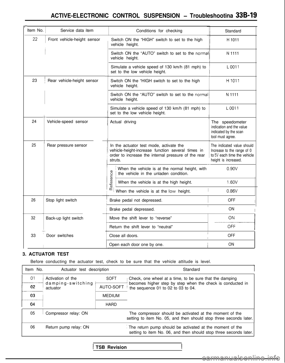
rItem No. IService data itemConditions for checking
Switch ON the “HIGH” switch to set to the high
vehicle height.Standard
H 1011
Switch ON the “AUTO” switch to set to the norma
vehicle height.N 1111
Simulate a vehicle speed of 130 km/h (81 mph) to
set to the low vehicle height.ILO011
-cSwitch ON the “HIGH switch to set to the high
vehicle height.HI011
Switch ON the “AUTO” switch to set to the norma
vehicle height.
N 1111
Simulate a vehicle speed of 130 km/h (81 mph) to
set to the low vehicle height.LOO11
Actual driving The speedometer
indication and the value
indicated by the scan
tool must agree.
In the actuator test mode, activate theThe indicated value should
vehicle-height-increase function several times inIncrease to the range of 0
order to increase the internal pressure of the rearto 5V each time the vehicle
struts.height is increased.-
8
i When the vehicle is at the normal height, with
iE Ithe vehicle in the unladen condition. 0.9ov
Front vehicle-height sensor
23
’/Rear vehicle-height sensor
-4
c
24Vehicle-speed sensor
t25Rear pressure sensor
Fa,%When the vehicle is at the high height.
[r i When the vehicle is at the low height.
1.6OV
I0.86VT
26Stop light switch Brake pedal not depressed.IOFFI
Brake pedal depressed.IONIc
32Back-up light switch
33
TDoor switches
I
Move the shift lever to “reverse”
-E-----l
-
Return the shift lever to “neutral”
Close all doors.
IOFF/
Open each door one by one.ION
3. ACTUATOR TEST Before conducting the actuator test, check to be sure that the vehicle a\
ttitude is level.
Item No. Actuator test description Standard
01~
!l
Activation of theSOFT
damping-switching i
I Check, one wheel at a time, to be sure that the damping
02 actuator
t’ becomes higher step by step when the check is conducted in
AUTO-SOFT ~the sequence 01 to 02 to 03 to 04.
03MEDIUM
04 HARD
05
Compressor relay: ON The compressor should be activated at the moment of the
setting to item No. 05, and then should stop three seconds later.
Return pump relay: ON ~
The return pump should be activated at the moment of the
setting to item No. 06, and then should stop three seconds later.
06
1 TSB Revision
Page 978 of 1273
ACTIVE-ELECTRONIC CONTROL SUSPENSION - Troubleshooting 33B-39
Operation
The ACTIVE-ECS system functions, in order to improve the “air drag” characteristic, to adjust the During the nighttime, however, in order to prevent
vehicle height to the LOW setting at the front end deviation of the headlight beams from the required
only during the daytime when the vehicle speed directional path, the vehicle height is adjusted to the
reaches 90 km/h
(56 mph) or higher and continues LOW setting for both the front end and the rear end
at that speed for a period of ten seconds or longer. when signals from the headlight relay are input.
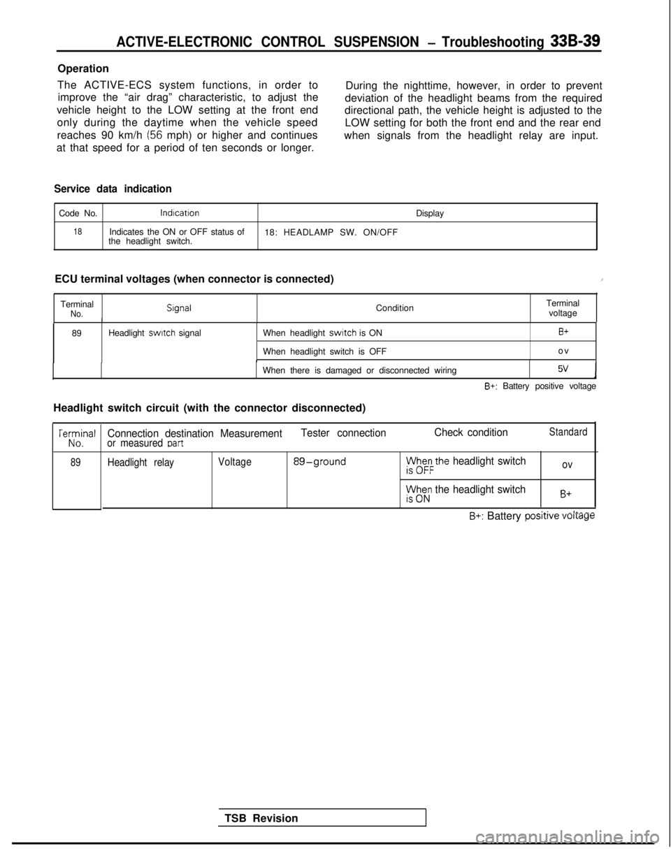
Service data indication
Code No.lndlcation
Display
18Indicates the ON or OFF status of
18: HEADLAMP SW. ON/OFF
the headlight switch.
ECU terminal voltages (when connector is connected)
/
TerminalNo. Slgnal
ConditionTerminal
voltage
89 Headlight switch
signal When headlight
switch is ON
When headlight switch is OFFB+
o
v
When there is damaged or disconnected wiring
5vJ
B+: Battery positive voltage
Headlight switch circuit (with the connector disconnected)
TSB Revision
TeKJna’
89
Connection destination Measurement Tester connectionCheck conditionStandard
or measured Dart
Headlight relayVoltage 89-groundph&the headlight switchov
rt$z; the headlight switchB+
~.A.-II___B+: Battery posrrrve voltage
Page 1025 of 1273
33B-86 ACTIVE-ELECTRONIC CONTROL SUSPENSION - ~~u,:~%i?:~~~~
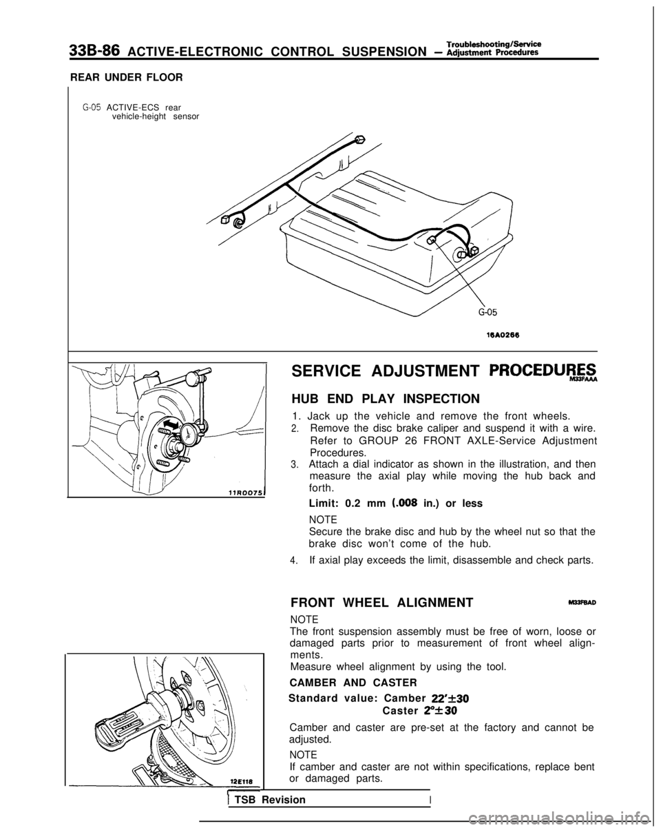
REAR UNDER FLOOR
G-05 ACTIVE-ECS rear vehicle-height sensor
16A0266
SERVICE ADJUSTMENT PROCEDURAZ
HUB END PLAY INSPECTION
1. Jack up the vehicle and remove the front wheels.
2.Remove the disc brake caliper and suspend it with a wire.
Refer to GROUP 26 FRONT AXLE-Service Adjustment
Procedures.
3.Attach a dial indicator as shown in the illustration, and then measure the axial play while moving the hub back and
forth.
Limit: 0.2 mm t.008
in.) or less
NOTE
Secure the brake disc and hub by the wheel nut so that the
brake disc won’t come of the hub.
4.If axial play exceeds the limit, disassemble and check parts.
FRONT WHEEL ALIGNMENT
M33f6AD
NOTE
The front suspension assembly must be free of worn, loose or
damaged parts prior to measurement of front wheel align- ments.
Measure wheel alignment by using the tool.
CAMBER AND CASTER
Standard value: Camber
22’f30
Caster ZY30
Camber and caster are pre-set at the factory and cannot be
adjusted.
NOTE
If camber and caster are not within specifications, replace bent
or damaged parts.
I TSB RevisionI
Page 1026 of 1273
ACTIVE-ELECTRONIC CONTROL SUSPENSIONService Adjustment- Procedures33B-87
Alarm light
With scan tool
Diagnostic check terminal
Serial/
on-board
diagnostic’
outwt
TSB RevisionI
Serial/diagnostic
-switching input
Simulated vehicle-
-speed input
-Ground
16LOO91
!
TOE-IN
Standard value:
Ok3 mm (Of.12 in.)
1. Adjust the toe-in by undoing the clips and turning the left and right tie rod turnbuckles by the same amount (in
opposite directions).
2. The toe will move out as the left turnbuckle
is turned
toward the front of the vehicle and the right turnbuckle is
turned toward the rear of the vehicle.
3.For each half turn of the left and right tie rods, the toe-in will
be adjusted by 6 mm
(.24 in.).
4.After making the adjustments, use a turning radius gage to confirm that the steering wheel turning angle is within the
standard value range. (Refer to GROUP 37A
POWER
STEERING-Service Adjustment Procedures.)
WHEEL BEARING ADJUSTMENT
M33FcAA
Bearing preload is pre-set to the specified value by design and
therefore can not be adjusted.
ALARM LIGHT CHECK
MPFNAC
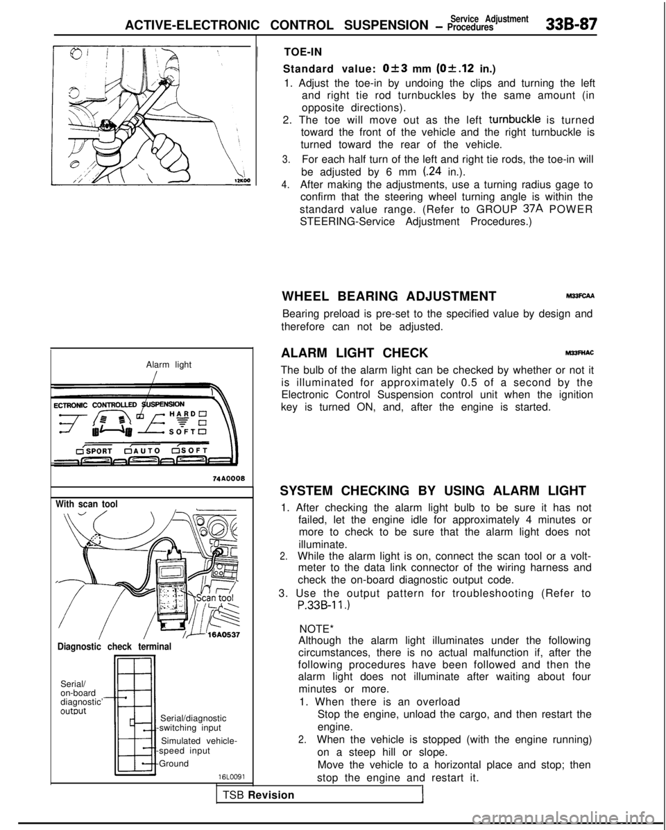
The bulb of the alarm light can be checked by whether or not it is illuminated for approximately 0.5 of a second by the
Electronic Control Suspension control unit when the ignition
key is turned ON, and, after the engine is started.
SYSTEM CHECKING BY USING ALARM LIGHT 1. After checking the alarm light bulb to be sure it has not failed, let the engine idle for approximately 4 minutes ormore to check to be sure that the alarm light does not
illuminate.
2.While the alarm light is on, connect the scan tool or a volt- meter to the data link connector of the wiring harness and
check the on-board diagnostic output code.
3. Use the output pattern for troubleshooting (Refer to
P.33B-11.)
NOTE*
Although the alarm light illuminates under the following
circumstances, there is no actual malfunction if, after the
following procedures have been followed and then the
alarm light does not illuminate after waiting about four
minutes or more.
1. When there is an overload Stop the engine, unload the cargo, and then restart the
engine.
2.When the vehicle is stopped (with the engine running)
on a steep hill or slope.Move the vehicle to a horizontal place and stop; then
stop the engine and restart it.
Page 1031 of 1273
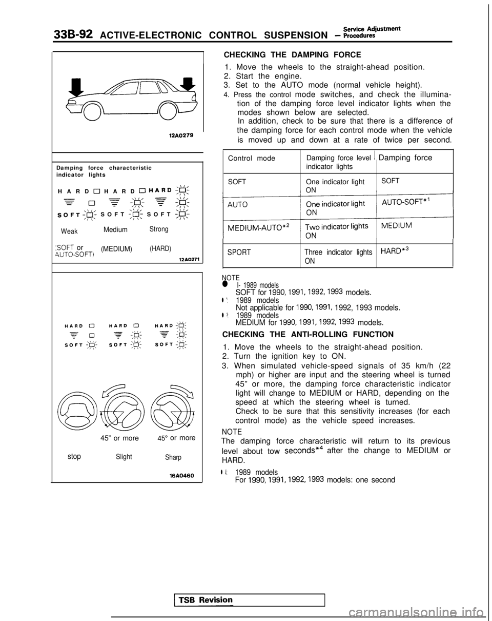
33B-92 ACTIVE-ELECTRONIC CONTROL SUSPENSION - ~~:%:?stment
CHECKING THE DAMPING FORCE
12A0279
Damping force characteristic
indicator lights
,\,IHARD 0 HARD 0 HARD;g!;
=-\\I, =\\ l,=0 -=-,F; f;F:
SOFT ,gi SOFT
:SOFT or(MEDIUM)(HARD)4UTOSOFT)12AQ271
./I,HARD 0HARD 0HARD ;g;
z-0 -\k 3,\I I,SOFT ;p;SOFT ;R-SOFT I@;
45” or more45” or more
stopSlight
Sharp
16AQ460
1. Move the wheels to the straight-ahead position.
2. Start the engine.
3. Set to the AUTO mode (normal vehicle height).
4. Press the control mode switches, and check the illumina-
tion of the damping force level indicator lights when themodes shown below are selected.In addition, check to be sure that there is a difference of
the damping force for each control mode when the vehicle
is moved up and down at a rate of twice per second.
Control mode Damping force level
1 Damping force
indicator lights
SOFTOne indicator light
ON SOFT
SPORT
I
Three indicator lightsHARDe3
ON
NOTEl I- 1989 modelsSOFT for 1990,1991,1992,1993 models.l *:1989 modelsNot applicable for 1990,1991, 1992, 1993 models.l 3:1989 modelsMEDIUM for 1990,1991,1992,1993 models.
CHECKING THE ANTI-ROLLING FUNCTION
1. Move the wheels to the straight-ahead position.
2. Turn the ignition key to ON.
3. When simulated vehicle-speed signals of 35 km/h (22 mph) or higher are input and the steering wheel is turned
45” or more, the damping force characteristic indicator light will change to MEDIUM or HARD, depending on the
speed at which the steering wheel is turned. Check to be sure that this sensitivity increases (for each
control mode) as the vehicle speed increases.
NOTE
The damping force characteristic will return to its previous
level about tow seconds*4
after the change to MEDIUM or
HARD.
l 4:1989 modelsFor 1990,1991,1992,1993
models: one second
Page 1037 of 1273
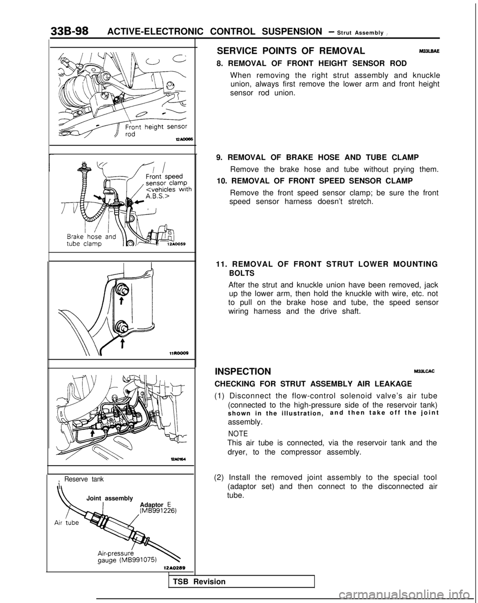
33B-98ACTIVE-ELECTRONIC CONTROL SUSPENSION - Strut Assembly i
SERVICE POINTS OF REMOVALM33lBAE
8. REMOVAL OF FRONT HEIGHT SENSOR RODWhen removing the right strut assembly and knuckleunion, always first remove the lower arm and front height
sensor rod union. l1RoooP
-
,Reserve tank
Joint assembly
Adaptor E
1 -1210289
9. REMOVAL OF BRAKE HOSE AND TUBE CLAMP
Remove the brake hose and tube without prying them.
10. REMOVAL OF FRONT SPEED SENSOR CLAMP
Remove the front speed sensor clamp; be sure the front
speed sensor harness doesn’t stretch.
11. REMOVAL OF FRONT STRUT LOWER MOUNTING
BOLTS
After the strut and knuckle union have been removed, jack up the lower arm, then hold the knuckle with wire, etc. not
to pull on the brake hose and tube, the speed sensor wiring harness and the drive shaft.
INSPECTION
M33LCAC
CHECKING FOR STRUT ASSEMBLY AIR LEAKAGE
(1) Disconnect the flow-control solenoid valve’s air tube (connected to the high-pressure side of the reservoir tank)
shown in the illustration, and then take off the join
t
assembly.
NOTE
This air tube is connected, via the reservoir tank and the dryer, to the compressor assembly.
(2) Install the removed joint assembly to the special tool (adaptor set) and then connect to the disconnected air
tube.
TSB Revision
Page 1038 of 1273
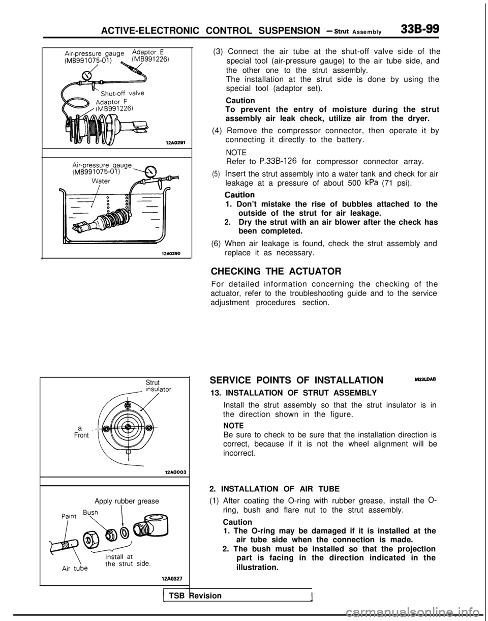
ACTIVE-ELECTRONIC CONTROL SUSPENSION - Strut Assembly33B-99
12Ao291
Strutator
a
.
Front
12AO.0003
Apply rubber grease
WA0327
(3) Connect the air tube at the shut-off valve side of the
special tool (air-pressure gauge) to the air tube side, and
the other one to the strut assembly.
The installation at the strut side is done by using the special tool (adaptor set).
Caution
To prevent the entry of moisture during the strut
assembly air leak check, utilize air from the dryer.
(4) Remove the compressor connector, then operate it by connecting it directly to the battery.
NOTE
Refer to P.33B-126 for compressor connector array.
(5) Insert
the strut assembly into a water tank and check for air
leakage at a pressure of about 500
kPa (71 psi). Caiition
1. Don’t mistake the rise of bubbles attached to the outside of the strut for air leakage.
2.Dry the strut with an air blower after the check has
been completed.
(6) When air leakage is found, check the strut assembly and replace it as necessary.
CHECKING THE ACTUATOR For detailed information concerning the checking of the
actuator, refer to the troubleshooting guide and to the service
adjustment procedures section.
SERVICE POINTS OF INSTALLATION
M33LDAB
13. INSTALLATION OF STRUT ASSEMBLY Install the strut assembly so that the strut insulator is in
the direction shown in the figure.
NOTE
Be sure to check to be sure that the installation direction is
correct, because if it is not the wheel alignment will be
incorrect.
2. INSTALLATION OF AIR TUBE
(1) After coating the O-ring with rubber grease, install the
O-
ring, bush and flare nut to the strut assembly.
Caution 1. The O-ring may be damaged if it is installed at the
air tube side when the connection is made.
2. The bush must be installed so that the projection part is facing in the direction indicated in the
illustration.
1 TSB Revision
Page 1040 of 1273
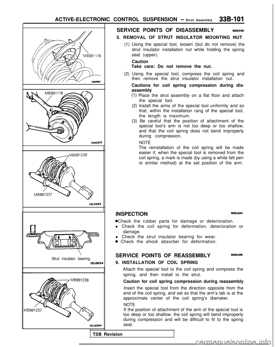
ACTIVE-ELECTRONIC CONTROL SUSPENSION - Strut Assembly33B-101
12AO275
12LO254
Strut insulator bearing12LOO34
12LO254
SERVICE POINTS OF DISASSEMBLYM23LFAD
5. REMOVAL OF STRUT INSULATOR MOUNTING NUT
(1) Using the special tool, loosen (but do not remove) the strut insulator installation nut while holding the spring
seat (upper).
Caution
Take care: Do not remove the nut.
(2) Using the special tool, compress the coil spring and then remove the strut insulator installation nut.
Cautions for coil spring compression during dis- assembly
(1) Place the strut assembly on a flat floor and attach
the special tool.
(2) Install the arms of the special tool uniformly and so that, within the installation rang of the special tool,
the length is maximum.
(3) Be careful that the position of attachment of the special tool’s arm is not too deep or too shallow,
and that the coil spring does not bend improperly during compression.
NOTE
The reinstallation of the coil spring will be made easier if, when the special tool is removed from the
coil spring, a mark is made (by using a white felt pen
or similar method) at the set position of the arm.
INSPECTION MPLGAC
0 Check the rubber parts for damage or deterioration.
l Check the coil spring for deformation, deterioration or
damage.
l Check the strut insulator bearing for wear.
a Check the shock absorber for deformation.
SERVICE POINTS OF REASSEMBLY
M32LHAs
9. INSTALLATION OF COIL SPRING
TSB Revision Attach the special tool to the coil spring and compress the
spring, and then install to the strut.
Caution for coil spring compression during reassembly
Insert the special tool from the direction opposite from the
end of the coil spring, and set so that the arm’s tab is at the
approximate center of the coil spring’s diameter.
NOTE
If the position of attachment of the arm of the special tool is
too deep or too shallow, the coil spring will bend improperly
during compression and will be difficult to fit to the spring
seat.
Page 1073 of 1273

33B-134ACTIVE-ELECTRONIC CONTROL SUSPENSION - Air tube
Air
Tab
\Joint asset
MB991229nbly
12AO280
Dryer lower pa
\
t-t connection
part Flare-nut type
Loosen the joint and pull out the air tube.
NOTE
12A0278
When loosening the joint at the lower part of the dryer, use aspanner to hold the hexagonal part of the joint installation part
to prevent it from turning.
Caution
In order to prevent the entry of dust, foreign material, etc.,
use vinyl tape or similar material to close the end of the air
tube and the opening at the device side.
tLe*~Identification
colorJoint assembly 12AO363
1210278
SERVICE POINTS OF REMOVAL
REMOVAL OF AIR TUBES
One-touch type
(1) Push the special tool inward, in direction
0 shown in the
figure, in order to expand the tabs of the joint.
(2) Pull out the air tube, together with the special tool, in direction
0.
SERVICE POINTS OF INSTALLATION
INSTALLATION OF AIR TUBES
One-touch type Push the air tube in the joint assembly at the device side until
a “click” is heard, and then check to be sure that the tabs of
the joint assembly are securely affixed to the air tube.
Caution
Before connecting the air tube, check to be sure that the
identification color of the tube and the color at the joint
agree.
Flare-nut type
First insert the air tube until resistance is felt, and then press
the tube further inward to the paint mark on the air tube.
Caution
Air leakage may occur if the air tube connection is not
complete and secure.
INSPECTION AFTER AIR TUBE INSTALLATION
(1) Check for double-folding at the rolling diaphragm. (Refer to
P.33B-89.)
(2) Apply a soap-and-water solution to the joint part to check for air leakage; also visually check the air tube forbreakage, crushing, pinching, etc.
TSB Revision