set MITSUBISHI GALANT 1989 Service Repair Manual
[x] Cancel search | Manufacturer: MITSUBISHI, Model Year: 1989, Model line: GALANT, Model: MITSUBISHI GALANT 1989Pages: 1273, PDF Size: 37.62 MB
Page 1191 of 1273
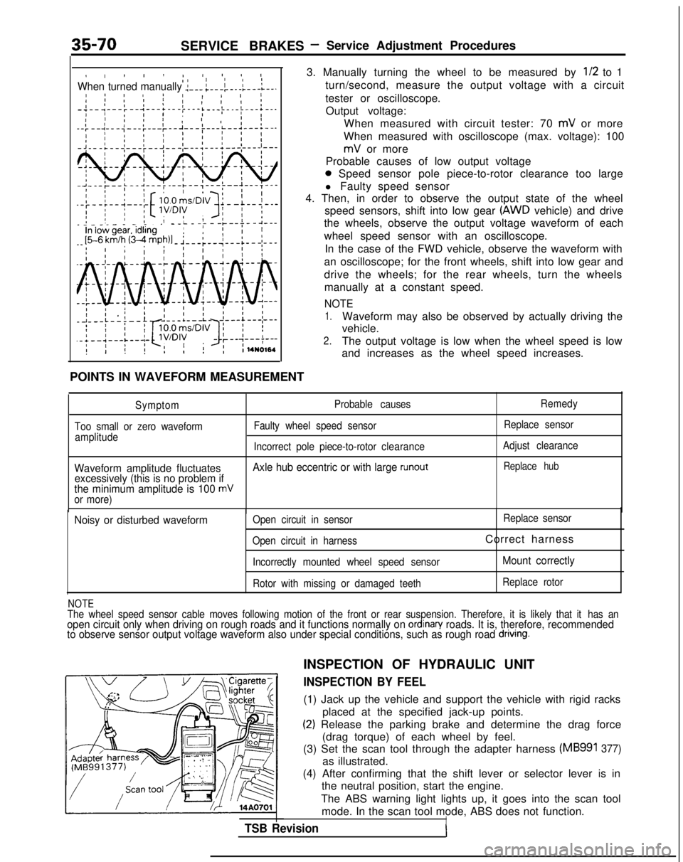
35-70SERVICE BRAKES- Service Adjustment Procedures
I, ! I ! I4 IO II IIWhen turned manually :---;---i-.-l---L--.I 8 ! IaI 1 11 1 II ’I 1’ I I I;-;--1---:--‘---+---t---i ’I IL---)-.-i---+--.II ’ I I 1 , 1 ,I
--:--~---;---:---~--~--
POINTS IN WAVEFORM MEASUREMENT
3. Manually turning the wheel to be measured by
l/2 to 1
turn/second, measure the output voltage with a circuit
tester or oscilloscope. Output voltage: When measured with circuit tester: 70
mV or more
When measured with oscilloscope (max. voltage): 100
mV or more
Probable causes of low output voltage
0 Speed sensor pole piece-to-rotor clearance too large
l Faulty speed sensor
4. Then, in order to observe the output state of the wheel
speed sensors, shift into low gear
(AWD vehicle) and drive
the wheels, observe the output voltage waveform of each
wheel speed sensor with an oscilloscope.
In the case of the FWD vehicle, observe the waveform with
an oscilloscope; for the front wheels, shift into low gear and
drive the wheels; for the rear wheels, turn the wheels manually at a constant speed.
NOTE
1.Waveform may also be observed by actually driving the
vehicle.
2.The output voltage is low when the wheel speed is low
and increases as the wheel speed increases.
Symptom
Too small or zero waveform amplitude Probable causes
Faulty wheel speed sensor Remedy
Replace sensor
Incorrect pole piece-to-rotor clearanceAdjust clearance
Waveform amplitude fluctuates Axle hub eccentric or with large runoutReplace hub
excessively (this is no problem if
the minimum amplitude is 100 mVor more)
Noisy or disturbed waveformOpen circuit in sensor Replace
sensor
Open circuit in harness
Correct harness
Incorrectly mounted wheel speed sensorMount correctly
Rotor with missing or damaged teeth Replace rotor
NOTEThe wheel speed sensor cable moves following motion of the front or rear\
suspension. Therefore, it is likely that it
has anopen circuit only when driving on rough roads and it functions normally \
on ordinan/ roads. It is, therefore, recommended
to observe sensor output voltage waveform also under special conditions,\
such as rough road dnvlng.
TSB Revision
INSPECTION OF HYDRAULIC UNIT
INSPECTION BY FEEL
(1) Jack up the vehicle and support the vehicle with rigid racks
placed at the specified jack-up points.
(2) Release the parking brake and determine the drag force(drag torque) of each wheel by feel.
(3) Set the scan tool through the adapter harness
(MB991 377)
as illustrated.
(4) After confirming that the shift lever or selector lever is in the neutral position, start the engine.
The ABS warning light lights up, it goes into the scan tool mode. In the scan tool mode, ABS does not function.
I
Page 1207 of 1273
35-86SERVICE BRAKES - Brake Booster
SERVICE POINTS OF REMOVALM35JBAK
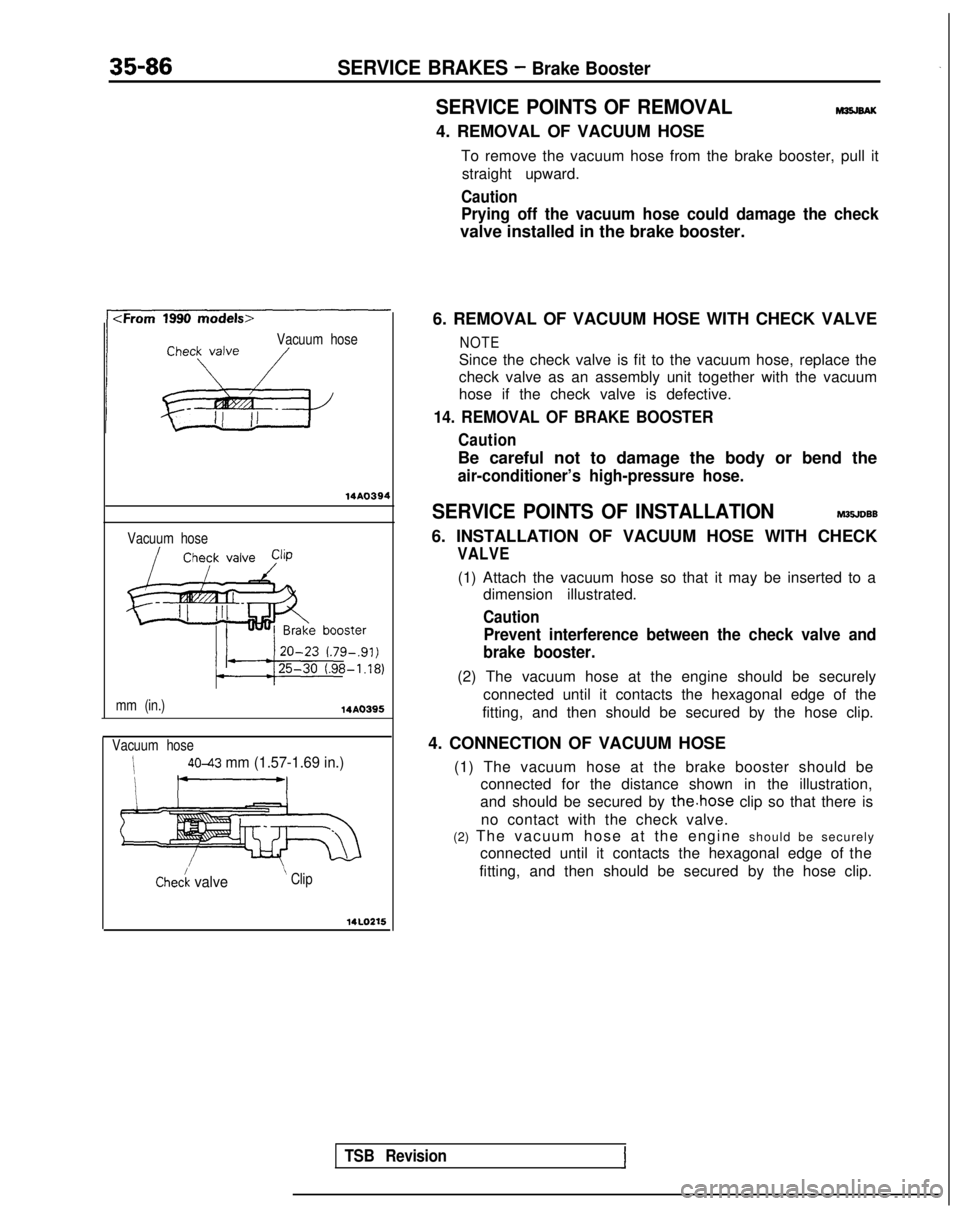
4. REMOVAL OF VACUUM HOSETo remove the vacuum hose from the brake booster, pull itstraight upward.
Caution
Prying off the vacuum hose could damage the check
valve installed in the brake booster.
Vacuum hose
14AO394
Vacuum hose
mm (in.)
14A0395
Vacuum hose
i4043 mm (1.57-1.69 in.)
I I__/
Chec/k valve ’ Clip
14LOZ15
6. REMOVAL OF VACUUM HOSE WITH CHECK VALVE
NOTE
Since the check valve is fit to the vacuum hose, replace the
check valve as an assembly unit together with the vacuum
hose if the check valve is defective.
14. REMOVAL OF BRAKE BOOSTER
Caution
Be careful not to damage the body or bend the
air-conditioner’s high-pressure hose.
SERVICE POINTS OF INSTALLATIONM35JDBB
6. INSTALLATION OF VACUUM HOSE WITH CHECK
VALVE
(1) Attach the vacuum hose so that it may be inserted to a
dimension illustrated.
Caution
Prevent interference between the check valve and
brake booster.
(2) The vacuum hose at the engine should be securely
connected until it contacts the hexagonal edge of the
fitting, and then should be secured by the hose clip.
4. CONNECTION OF VACUUM HOSE (1) The vacuum hose at the brake booster should be connected for the distance shown in the illustration,
and should be secured by
the.hose clip so that there is
no contact with the check valve.
(2) The vacuum hose at the engine should be securel
y
connected until it contacts the hexagonal edge of the
fitting, and then should be secured by the hose clip.
TSB Revision
Page 1214 of 1273
SERVICE BRAKES - Brake Line35-93
Brake hose
14w59314uooG7
SERVICE POINTS OF REMOVALM35KBAla
1. REMOVAL OF FRONT BRAKE HOSE/22. REAR BRAKE
HOSE
(1) Holding the lock nut on the brake hose side, loosen
the flared brake line nut.
(2) Pull off the brake hose clip and remove the brake hose from the bracket.
19. REMOVAL OF PROPORTIONING
VALVE/24. DELAY
VALVE
Do not disassemble the proportioning valve and delay
valve because its performance depends on the set load of
the spring.
INSPECTION
M35KCAA
l Check the brake tubes for cracks, crimps and corrosion.
l Check the brake hoses for cracks, damage and leakage.
0Check the flared brake line nuts for damage and leakage.
SERVICE POINTS OF INSTALLATION
M35KDAGa
15.CONNECTlON OF TUBE AND HOSE TO HYDRAULIC
UNIT
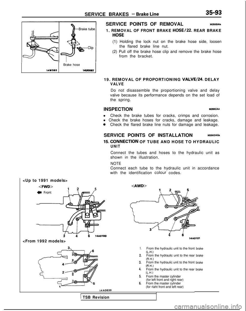
Connect the tubes and hoses to the hydraulic unit as
shown in the illustration.
NOTE
Connect each tube to the hydraulic unit in accordance
with the identification colour
codes.
414AOlOl
1.
2.
3.
4.
5.
6.
From the hydraulic unit to the front(L.H.)From the hydraulic unit to the rear(R.H.)From the hydraulic unit to the front(R.H.)From the hydraulic unit to the rear(L.H.)From the master cylinder
(for left front and right rear)
From the master cylinder
(for riaht front and left rear)
brake
brake
brake
brake
14A0639
1 TSB Revision
Page 1219 of 1273
35-98SERVICE BRAKES - Front Disc Brake
pin
Caliper
/support(pad, clip, shim) 1410356
Boot ring14KO5414G0054 14KO57SERVICE POINTS OF DISASSEMBLY M35LFAH
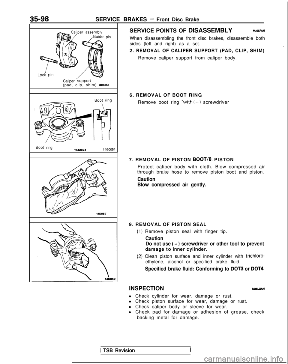
When disassembling the front disc brakes, disassemble both
sides (left and right) as a set.
2. REMOVAL OF CALIPER SUPPORT (PAD, CLIP, SHIM)
Remove caliper support from caliper body.
6. REMOVAL OF BOOT RING Remove boot ring
*with (-) screwdriver
7. REMOVAL OF PISTON
BOOT/8. PISTON
Protect caliper body with cloth. Blow compressed air
through brake hose to remove piston boot and piston.
Caution
Blow compressed air gently.
9. REMOVAL OF PISTON SEAL
(1
(2
) Remove piston seal with finger tip.
Caution Do not use
( - ) screwdriver or other tool to prevent
damage to inner cylinder.
I) Clean piston surface and inner cylinder with trichloro-
ethylene, alcohol or specified brake fluid.
Specified brake fluid: Conforming to DOT3 or DOT4
INSPECTIONM35LGAH
l Check cylinder for wear, damage or rust.
l Check piston surface for wear, damage or rust.
l Check caliper body or sleeve for wear.
l Check pad for damage or adhesion of grease, check
backing metal for damage.
1 TSB Revision
Page 1223 of 1273
35-102SERVICE BRAKES - Front Disc Brake
Boo; ring14KO5414G0054
14KO57
14UOO72
I
SERVICE POINTS OF DISASSEMBLYMSLFAK
When disassembling the front disc brakes, disassemble both
sides (left and right) as a set.
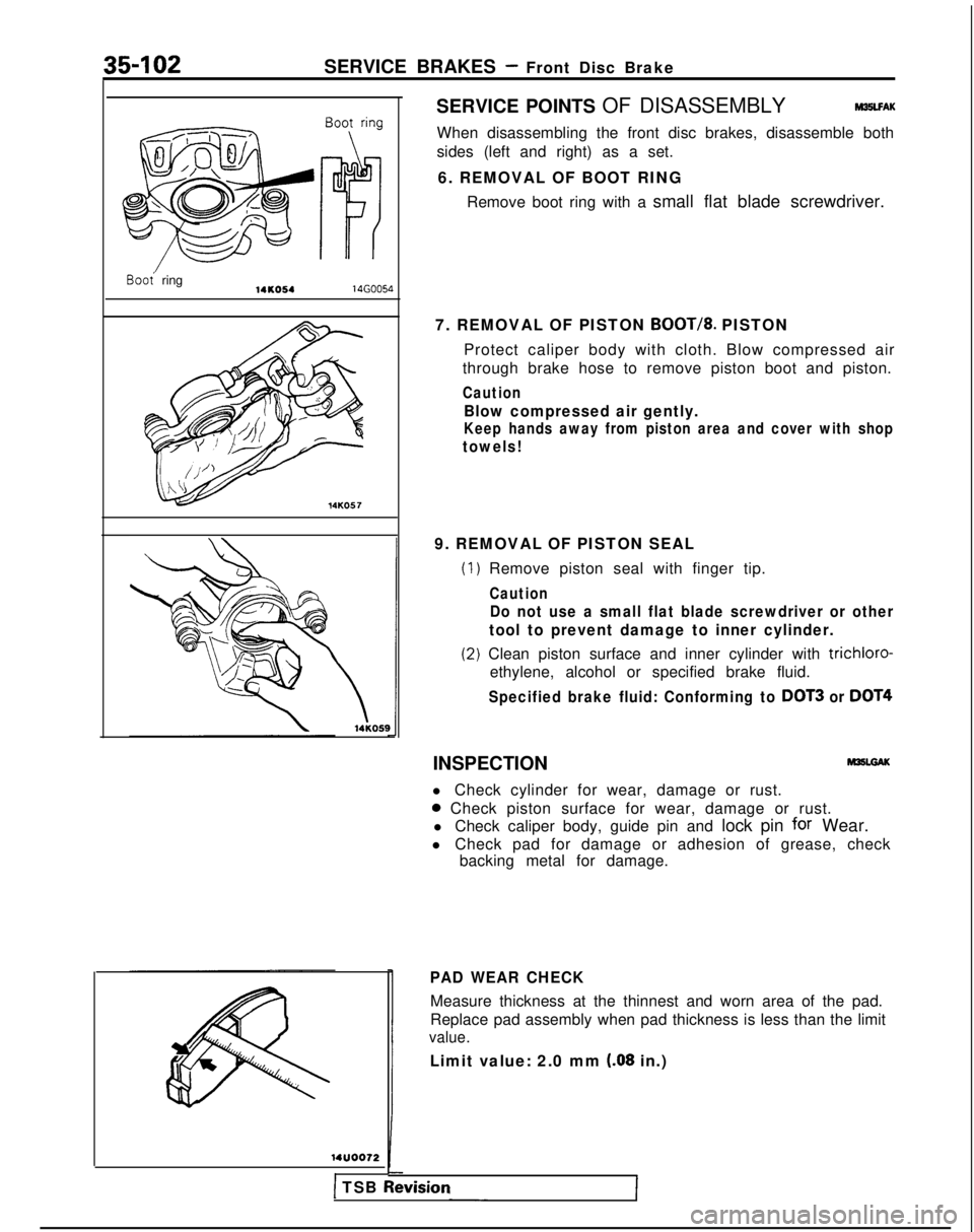
6. REMOVAL OF BOOT RING Remove boot ring with a small flat blade screwdriver.
7. REMOVAL OF PISTON
BOOT/8. PISTON
Protect caliper body with cloth. Blow compressed air
through brake hose to remove piston boot and piston.
Caution
Blow compressed air gently.
Keep hands away from piston area and cover with shop
towels!
9. REMOVAL OF PISTON SEAL
(1
(2
) Remove piston seal with finger tip.
Caution
Do not use a small flat blade screwdriver or other
tool to prevent damage to inner cylinder.
I) Clean piston surface and inner cylinder with trichloro-
ethylene, alcohol or specified brake fluid.
Specified brake fluid: Conforming to DOT3 or DOT4
INSPECTION
l Check cylinder for wear, damage or rust.
0 Check piston surface for wear, damage or rust.
l Check caliper body, guide pin and lock pin
for Wear.
l Check pad for damage or adhesion of grease, check backing metal for damage.
PAD WEAR CHECK
Measure thickness at the thinnest and worn area of the pad.
Replace pad assembly when pad thickness is less than the limit
value.
Limit value: 2.0 mm (.08 in.)
1 TSB Revrslon
Page 1227 of 1273
35-106SERVICE BRAKES - Front Disc Brake
SERVICE POINTS OF DISASSEMBLYM35LFAL
When disassembling the front disc brakes;disassemble both
sides (left and right) as a set.
14AO550 14AO55
14AO551
I 3a-
6. REMOVAL OF BOOT RING
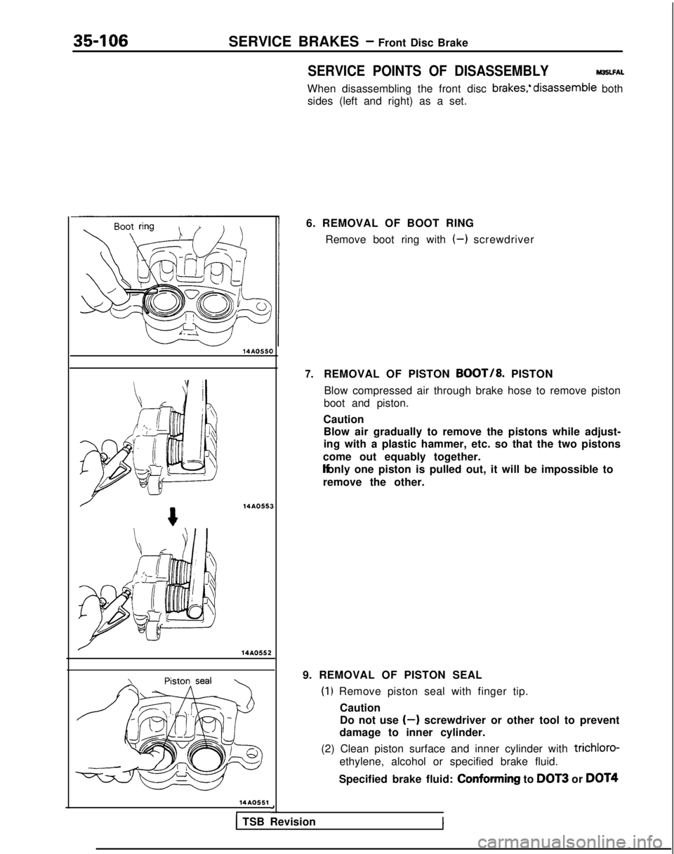
Remove boot ring with
(-) screwdriver
7.REMOVAL OF PISTON BOOT/8. PISTON
Blow compressed air through brake hose to remove piston
boot and piston.
Caution Blow air gradually to remove the pistons while adjust-
ing with a plastic hammer, etc. so that the two pistons
come out equably together. lf only one piston is pulled out, it will be impossible to
remove the other.
9. REMOVAL OF PISTON SEAL
(1) Remove piston seal with finger tip. Caution
Do not use
(-) screwdriver or other tool to prevent
damage to inner cylinder.
(2) Clean piston surface and inner cylinder with
trichloro-
ethylene, alcohol or specified brake fluid.
Specified brake fluid: Conforming
to
DOT3 or DOT4
1 TSB Revision
Page 1231 of 1273
35-110SERVICE BRAKES- Rear Drum Brake
14uoo75
14R0170
14K664r
nm (in.)G $%?-7?~i” >1,4A0361
Turn 180” or more anoreturn 360” or more.
(Repeat 3 times or
> more.)
D
I
-
INSPECTIONM36UCAM
BRAKE LINING THICKNESS CHECK
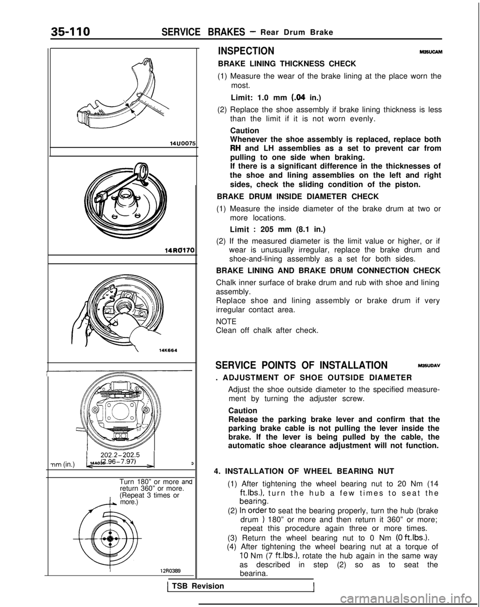
(1) Measure the wear of the brake lining at the place worn the most.
Limit: 1.0 mm
(84 in.)
(2) Replace the shoe assembly if brake lining thickness is less than the limit if it is not worn evenly.
Caution
Whenever the shoe assembly is replaced, replace both
RH and LH assemblies as a set to prevent car from
pulling to one side when braking.
If there is a significant difference in the thicknesses of
the shoe and lining assemblies on the left and right
sides, check the sliding condition of the piston.
BRAKE DRUM INSIDE DIAMETER CHECK
(1) Measure the inside diameter of the brake drum at two or more locations.
Limit
:205 mm (8.1 in.)
(2) If the measured diameter is the limit value or higher, or if wear is unusually irregular, replace the brake drum and
shoe-and-lining assembly as a set for both sides.
BRAKE LINING AND BRAKE DRUM CONNECTION CHECK
Chalk inner surface of brake drum and rub with shoe and lining
assembly. Replace shoe and lining assembly or brake drum if very
irregular contact area.
NOTE
Clean off chalk after check.
SERVICE POINTS OF INSTALLATION M35UDAV
. ADJUSTMENT OF SHOE OUTSIDE DIAMETER Adjust the shoe outside diameter to the specified measure-ment by turning the adjuster screw.
Caution
Release the parking brake lever and confirm that the
parking brake cable is not pulling the lever inside the
brake. If the lever is being pulled by the cable, the
automatic shoe clearance adjustment will not function.
4. INSTALLATION OF WHEEL BEARING NUT (1) After tightening the wheel bearing nut to 20 Nm (14 ft.lbs.),
turn the hub a few times to seat the
(2)
~~~~~‘to seat the bearing properly, turn the hub (brake
drum
) 180” or more and then return it 360” or more;
repeat this procedure again three or more times.
(3) Return the wheel bearing nut to 0 Nm
(0 ftlbs.).
(4) After tightening the wheel bearing nut at a torque of
10 Nm (7 ft.1b.s.). rotate the hub again in the same way
as described in step (2) so as to seat the bearina.
1 TSB Revision
Page 1232 of 1273
SERVICE BRAKES - Rear Drum Brake/Rear Brake Wheel Cylinder35-I 11
(5) Then once again tighten the wheel bearing nut to 10
Nm (7
ft.lbs.).
(6) Install the lock cap and split pin.
(7) If the position of the cotter pin is not matched with the
holes of the lock cap, reposition the lock cap so that the
holes align. If this can not be accomplished, back off the
nut by not more than 15”.
Caution
Check to be sure that the lock nut cannot b
e
loosened manually.
(8) After setting the split pin in place, seat the bearing in the same manner as in step (2).
REAR BRAKE WHEEL CYLINDER
REMOVAL AND INSTALLATION
8-12 Nm?6-9 ft.lbs./
-
r
14LO122
plant: ~AA;;~~n’: No.8513
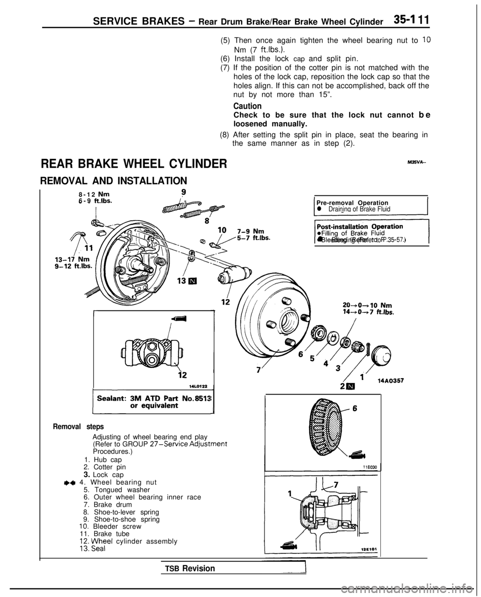
Removal steps
Adjusting of wheel bearing end play (Refer to GROUP 27-Service AdjustmentProcedures.)
1. Hub cap
2. Cotter pin
3. Lock cap
~~ 4. Wheel bearing nut
5. Tongued washer
6. Outer wheel bearing inner race
7. Brake drum
8. Shoe-to-lever spring
9. Shoe-to-shoe spring
10. Bleeder screw
11. Brake tube
VI Fezel cylinder assembly
IPre-removal Operationl Draininq of Brake FluidI
‘+iGJq
l Bleeding (Refer to P.35-57.)
20-+0+10 Nm 14-+0-+7
fklbs.
2& ‘. 14A0357
TSB Revision
Page 1233 of 1273
35-112SERVICE BRAKES - Rear Brake Wheel Cylinder
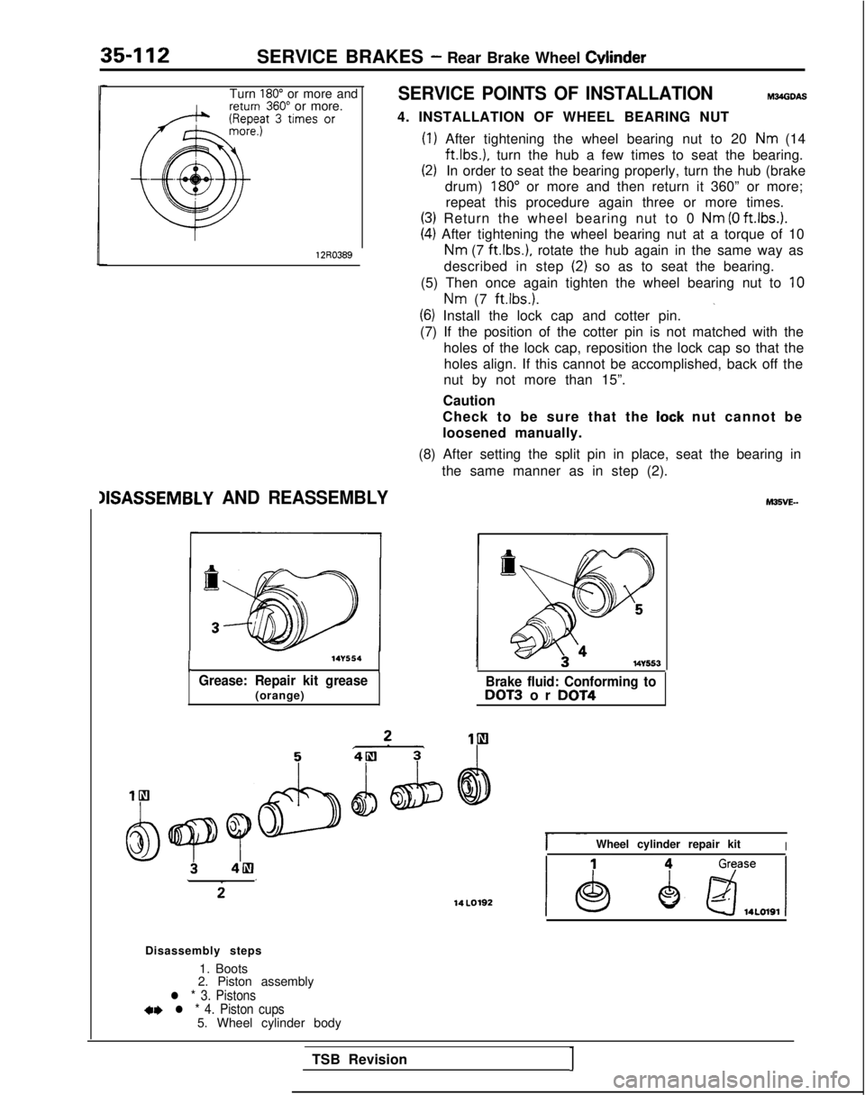
Turn 180” or more and360” or more.SERVICE POINTS OF INSTALLATIONm34obw
4. INSTALLATION OF WHEEL BEARING NUT
12R0389
(1) After tightening the wheel bearing nut to 20 Nm (14ft.lbs.),
turn the hub a few times to seat the bearing.
(2)In order to seat the bearing properly, turn the hub (brake
drum)
180” or more and then return it 360” or more;
repeat this procedure again three or more times.
(3) Return the wheel bearing nut to 0 Nm (0 ft.lbs.).
(4) After tightening the wheel bearing nut at a torque of 10
Nm (7
ft.lbs.),
rotate the hub again in the same way as
described in step
(2) so as to seat the bearing.
(5) Then once again tighten the wheel bearing nut to
10
Nm (7 ft.lbs.).
_(6) Install the lock cap and cotter pin.
(7) If the position of the cotter pin is not matched with the holes of the lock cap, reposition the lock cap so that theholes align. If this cannot be accomplished, back off the
nut by not more than 15”.
Caution
Check to be sure that the
lock nut cannot be
loosened manually.
(8) After setting the split pin in place, seat the bearing in the same manner as in step (2).
IISASSEMBLY AND REASSEMBLY
I
-14Y554
Grease: Repair kit grease(orange)Brake fluid: Conforming toDOT3 or DOT4 14
LO192
hl35VE-
I- ~~Wheel cylinder repair kitI
Disassembly steps
1. Boots
2. Piston assembly
l * 3. Pistons+* l * 4. Piston cups5. Wheel cylinder body
TSB Revision
1
Page 1234 of 1273
SERVICE BRAKES -Rear Brake Wheel Cylinder35-113
MB991008
Have the lip facing upwards.
14uoo93
SERVICE POINTS OF DISASSEMBLYM35VFAE
When disassembling the wheel cylinders, disassemble bothsides (left and right) as a set.
4. REMOVAL OF PISTON CUPS
Remove the piston cup, being careful not to damage the
piston.
INSPECTIONM35VGAD
Check the piston and wheel cylinder walls for rust or damage,
and if there is any abnormality, replace the entire wheel
cylinder assembly.
SERVICE POINTS OF REASSEMBLYM35VHAK
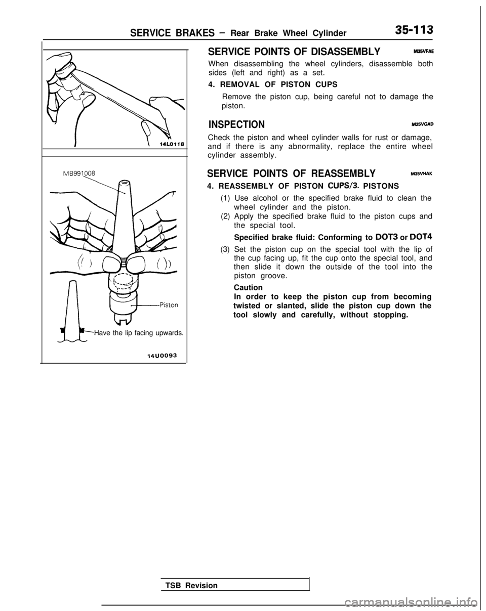
4. REASSEMBLY OF PISTON CUPS/3.
PISTONS
(1) Use alcohol or the specified brake fluid to clean the wheel cylinder and the piston.
(2) Apply the specified brake fluid to the piston cups and the special tool.
Specified brake fluid: Conforming to DOT3
or DOT4
(3) Set the piston cup on the special tool with the lip of the cup facing up, fit the cup onto the special tool, and
then slide it down the outside of the tool into the
piston groove.
Caution In order to keep the piston cup from becoming
twisted or slanted, slide the piston cup down the
tool slowly and carefully, without stopping.
TSB Revision