set MITSUBISHI GALANT 1989 Service Owners Manual
[x] Cancel search | Manufacturer: MITSUBISHI, Model Year: 1989, Model line: GALANT, Model: MITSUBISHI GALANT 1989Pages: 1273, PDF Size: 37.62 MB
Page 834 of 1273
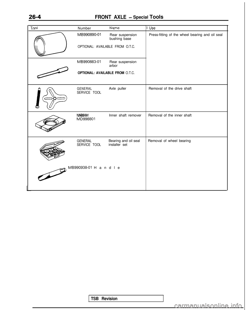
26-4FRONT AXLE- Special Tools
TdNumberNameI Use. .-. .------.
CD
MB990890-01
Rear suspension Press-fitting of the wheel bearing and oil seal
bushing base
OPTIONAL: AVAILABLE FROM O.T.C. MB990883-01
Rear suspension
arbor
/
OPTIONAL: AVAILABLE FROM O.T.C.
\
J!D
GENERALAxle puller Removal of the drive shaft
SERVICE TOOL
000
1 MB991 248 or
Inner shaft remover
Removal of the inner shaft MD998801
GENERAL
SERVICE TOOLBearing and oil seal
installer set
Removal of wheel bearing
H MB990938-01
Handle
TSB Revision
Page 848 of 1273
26-18FRONT AXLE - Drive Shaft (T.J.-R.J.
Type)
(7) For the boot band (small), cut away so that the length
of the band width remains, and then bend it over the
crimped band fitting.
For the boot band (large), cut away so that the length
until the clip holder position remains, and then secure
by the clip.
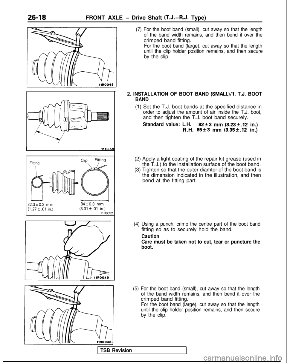
Fitting 32.3kO.3
mm
(I .27 t .Ol in.) llR0052
2. INSTALLATION OF BOOT BAND (SMALL)/l.
T.J. BOOT
BAND
(1) Set the T.J. boot bands at the specified distance in
order to adjust the amount of air inside the T.J. boot,
and then tighten the T.J. boot band securely.
Standard value: L.H.82+3 mm (3.23k.12
in.)
R.H.
85+3 mm (3.35f.12 in.)
(2) Apply a light coating of the repair kit grease (used in the T.J.) to the installation surface of the boot band.
(3) Tighten so that the outer diamter of the boot band is the dimension indicated in the illustration, and thenbend at the fitting part.
(4) Using a punch, crimp the centre part of the boot band
fitting so as to securely hold the band.
Caution
Care must be taken not to cut, tear or puncture the
boot.
(5) For the boot band (small), cut away so that the length of the band width remains, and then bend it over the
crimped band fitting.
For the boot band (large), cut away so that the length
until the clip holder position remains, and then secure
by the clip.
TSB Revision
Page 851 of 1273
FRONT AXLE -Drive Shaft (T.J.-B.J. Type)26-21
SERVICE POINTS OF REASSEMBLYM26OtlDE
9. INSTALLATION OF B.J.
BOOT/6.
T.J. BOOT
(1) Wrap vinyl tape around the splines on the drive shaft,
and then install the R.J. boot and T.J. boot, in that order.
order.
Caution
Distinguish between B.J. boot and T.J. boot parts
according to the section “Parts Distinction”, and be
sure to assemble them correctly.
(2) Fill the inside of the B.J. and B.J. boot with the
specified grease.
Specified grease: Repair kit grease
110 g (3.9 oz.)
NOTE
llAOl27
The grease in the repair kit should be divided in half for
use, respectively, at the joint and inside the boot.
(3) Secure the boot bands.
Caution
The boot bands should be tightened with the drive
shaft at a 0” joint angle.
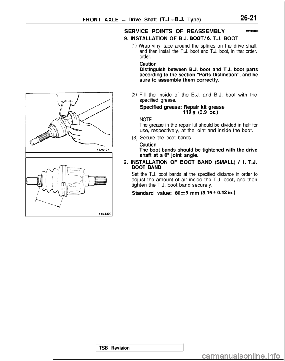
2. INSTALLATION OF BOOT BAND (SMALL)
/ 1. T.J.
BOOT BAND
Set the T.J. boot bands at the specified distance in order to
adjust the amount of air inside the T.J. boot, and then
tighten the T.J. boot band securely.
Standard value:
8023 mm (3.15f0.12 in.)
llE55E
TSB Revision
Page 854 of 1273
26-24FRONT AXLE - Drive Shaft
C
I1
c
1:
9
M8
Pry barTrarkaxlellE526
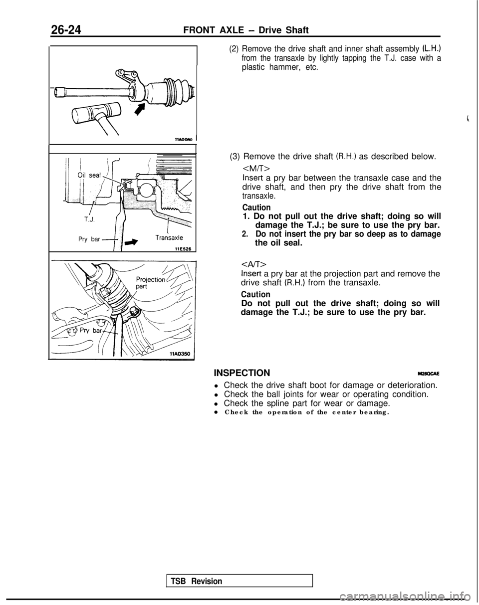
(2) Remove the drive shaft and inner shaft assembly (L.H.)
from the transaxle by lightly tapping the T.J. case with a
plastic hammer, etc.
(3) Remove the drive shaft (R.H.) as described below.
drive shaft, and then pry the drive shaft from the
transaxle.
Caution
1. Do not pull out the drive shaft; doing so will damage the T.J.; be sure to use the pry bar.
2.Do not insert the pry bar so deep as to damage
the oil seal.
Inset-t a pry bar at the projection part and remove the
drive shaft
(R.H.) from the transaxle.
Caution
Do not pull out the drive shaft; doing so will
damage the T.J.; be sure to use the pry bar.
INSPECTION l Check the drive shaft boot for damage or deterioration.
l Check the ball joints for wear or operating condition.
l Check the spline part for wear or damage.
l Check the operation of the center bearing.
TSB Revision
Page 859 of 1273
FRONT AXLE - Drive Shaft
26-2
9
Inner shaft
~
llA0083
Inner shaft
assembly
---.
T.J.case MB990938-01
Seal plate
-MB991 248
or MD998801
-...A
llAOO05
IHA0087 1
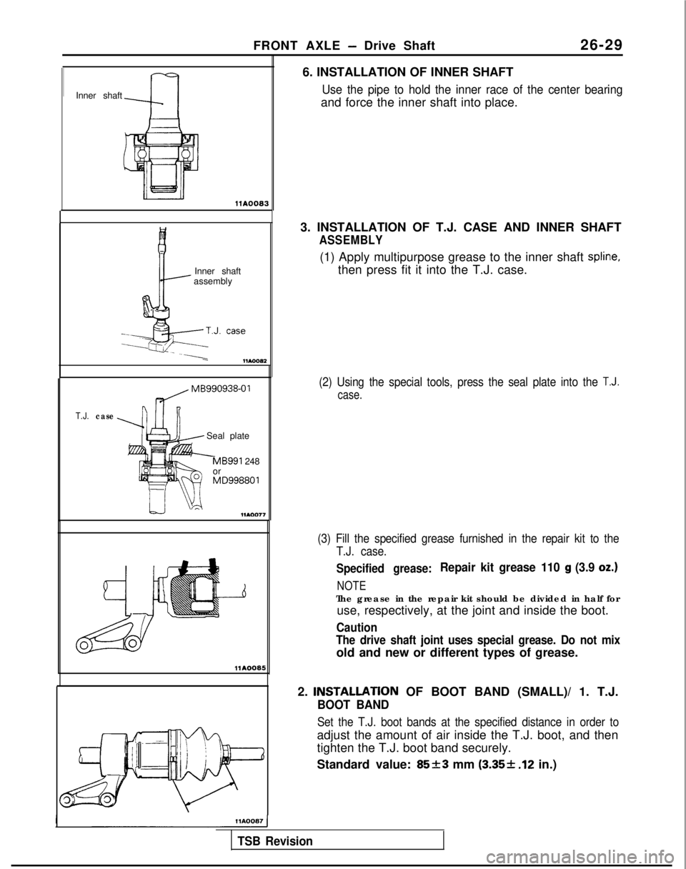
6. INSTALLATION OF INNER SHAFT
Use the pipe to hold the inner race of the center bearing
and force the inner shaft into place.
3. INSTALLATION OF T.J. CASE AND INNER SHAFT
ASSEMBLY
(1) Apply multipurpose grease to the inner shaft spline,
then press fit it into the T.J. case.
(2) Using the special tools, press the seal plate into the T.J.
case.
(3) Fill the specified grease furnished in the repair kit to the T.J. case.
Specified grease:Repair kit grease 110 g (3.9 oz.)
NOTE
The grease in the repair kit should be divided in half foruse, respectively, at the joint and inside the boot.
Caution
The drive shaft joint uses special grease. Do not mix
old and new or different types of grease.
2.
INSTALLATlON OF BOOT BAND (SMALL)/ 1. T.J.
BOOT BAND
Set the T.J. boot bands at the specified distance in order to
adjust the amount of air inside the T.J. boot, and then
tighten the T.J. boot band securely.
Standard value:
85+3 mm (3.35-1- .12 in.)
TSB Revision
Page 863 of 1273
REAR AXLE
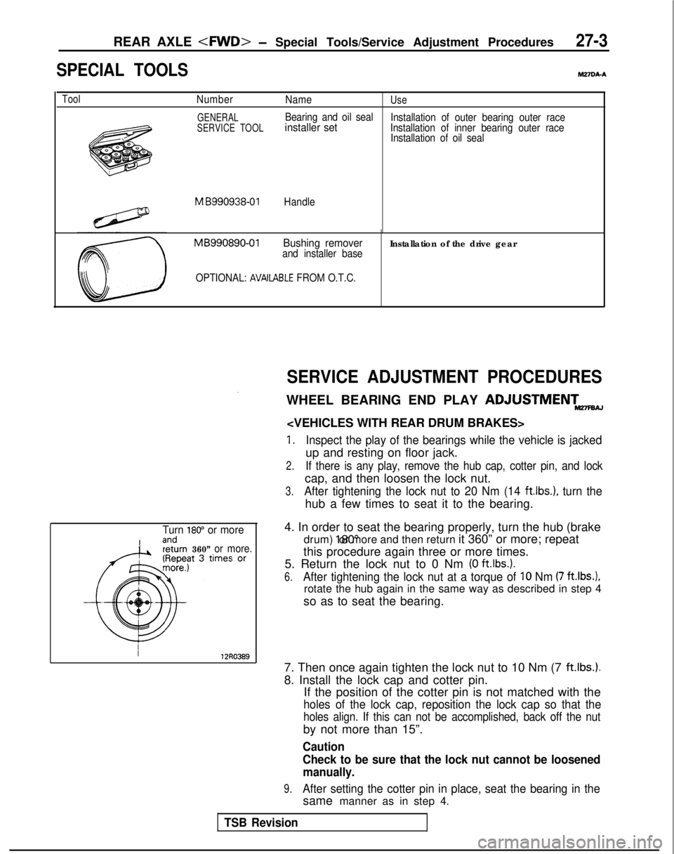
SPECIAL TOOLS
MZ7VA-A
ToolNumber
GENERAL
SERVICE TOOL
NameUse
Bearing and oil sealinstaller setInstallation of outer bearing outer race
Installation of inner bearing outer race Installation of oil seal
M B990938-01Handle
MB990890-01Bushing removerand installer baseInstallation of the drive gear
OPTIONAL: AVAIlABLE FROM O.T.C.
Turn 180” or more
360” or more.
SERVICE ADJUSTMENT PROCEDURES
WHEEL BEARING END PLAY ADJUSTMENTmw
1.Inspect the play of the bearings while the vehicle is jacked
up and resting on floor jack.
2.If there is any play, remove the hub cap, cotter pin, and lock
cap, and then loosen the lock nut.
3.After tightening the lock nut to 20 Nm (14 ft.lbs.1, turn the
hub a few times to seat it to the bearing.
4. In order to seat the bearing properly, turn the hub (brake drum) 180” or more and then return it 360” or more; repeat
this procedure again three or more times.
5. Return the lock nut to 0 Nm
(0 ft.lbs.).
6.After tightening the lock nut at a torque of 10 Nm (7 ft.lbs.1,
rotate the hub again in the same way as described in step 4
so as to seat the bearing.
7. Then once again tighten the lock nut to 10 Nm (7
ft.lbs.).
8. Install the lock cap and cotter pin. If the position of the cotter pin is not matched with the
holes of the lock cap, reposition the lock cap so that the
holes align. If this can not be accomplished, back off the nut
by not more than 15”.
Caution
Check to be sure that the lock nut cannot be loosened
manually.
9.After setting the cotter pin in place, seat the bearing in the
same manner as in step 4.
TSB Revision
Page 870 of 1273
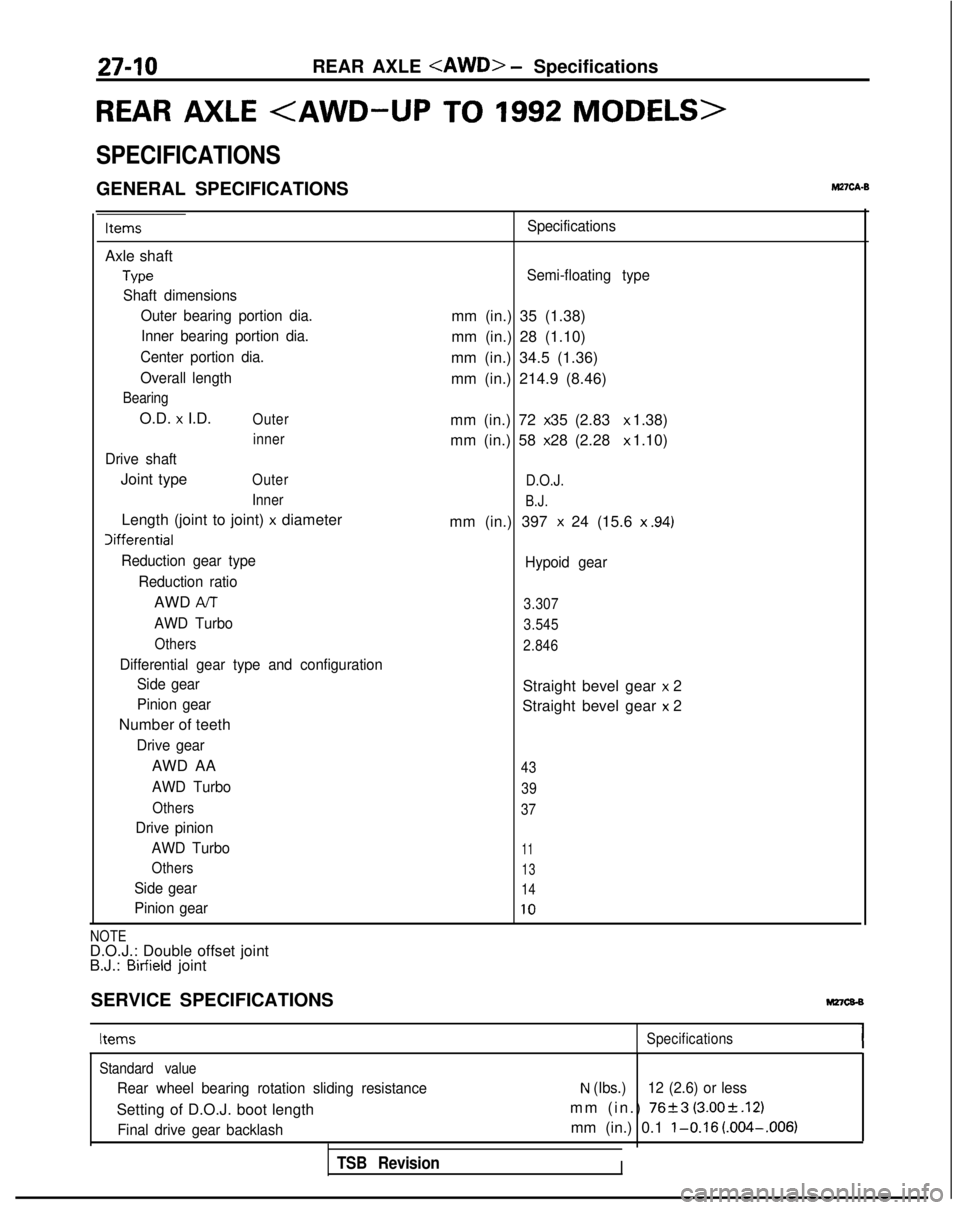
27-10REAR AXLE
REAR AXLE
SPECIFICATIONS
GENERAL SPECIFICATIONSM27cA.B
Items
Axle shaft
Type
Shaft dimensionsOuter bearing portion dia.Inner bearing portion dia.
Center portion dia.
Overall length
Bearing
O.D. x I.D.Outer inner
Drive shaft
Joint typeOuter
Inner
Length (joint to joint) x diameter Iifferential
Reduction gear type
Reduction ratio
AWD AIT
AWD Turbo
Others
Differential gear type and configurationSide gear
Pinion gear
Number of teeth
Drive gear
AWD AA
AWD Turbo
Others
Drive pinion
AWD Turbo
Others
Side gear
Pinion gear Specifications
Semi-floating type
mm (in.) 35 (1.38)
mm (in.) 28 (1.10)
mm (in.) 34.5 (1.36)
mm (in.) 214.9 (8.46)
mm (in.) 72 x 35 (2.83 x 1.38)
mm (in.) 58 x 28 (2.28 x 1.10)
D.O.J.
B.J.
mm (in.) 397 x 24 (15.6
x .94)
Hypoid gear
3.307
3.545
2.846
Straight bevel gear x 2
Straight bevel gear
x 2
43
39
37
11
13
14
10
NOTED.O.J.: Double offset joint
B.J.: Birfield joint
SERVICE SPECIFICATIONS
Mz7cs-s
Items Specifications
Standard value
Rear wheel bearing rotation sliding resistance
Setting of D.O.J. boot length
Final drive gear backlash
TSB Revision
N (Ibs.) 12 (2.6) or less
mm (in.) 7623 (3.00rt.12)
mm (in.) 0.1 l-0.16 (.004-.006)
I
Page 885 of 1273
REAR AXLE
t
Snap
inner race
1180116
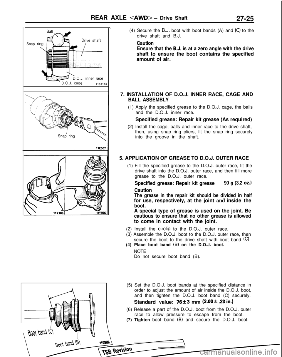
(4) Secure the B.J. boot with boot bands (A) and (C) to the
drive shaft and B.J.
Caution
Ensure that the B.J. is at a zero angle with the drive
shaft to ensure the boot contains the specified
amount of air.
7. INSTALLATION OF D.O.J. INNER RACE, CAGE AND
BALL ASSEMBLY
(1) Apply the specified grease to the D.O.J. cage, the balls and the D.O.J. inner race.
Specified grease: Repair kit grease (As required)
(2) Install the cage, balls and inner race to the drive shaft, then, using snap ring pliers, fit the snap ring securelyinto the groove in the shaft.
5. APPLICATION OF GREASE TO D.O.J. OUTER RACE (1) Fill the specified grease to the D.O.J. outer race, fit thedrive shaft into the D.O.J. outer race, and then fill more
grease to the D.O.J. outer race.
Specified grease: Repair kit grease90 g (3.2 OZ.)
Caution
The grease in the repair kit should be divided in half
for use, respectively, at the joint and inside the
boot.
A special type of grease is used on the joint. Be
cautious to ensure that no other grease is allowed
to come in contact with the joint.
(2) Install the circlip
to the D.O.J. outer race.
(3) Assemble the D.O.J. boot to the D.O.J. outer race, then secure the boot to the drive shaft with boot band
(C).
(4) Place boot band (B) on the D.O.J. boot.
NOTE
Do not secure boot band (B).
(5) Set the D.O.J. boot bands at the specified distance in order to adjust the amount of air inside the D.O.J. boot,
and then tighten the D.O.J. boot band (C) securely.
Standard value:
76f3 mm @JO+ 23 in.)
(6) Release a part of the D.O.J. boot from the D.O.J. outer race to allow pressure to escape from the boot.
(7) Tighten boot band
(B) and secure the D.O.J. boot.
Page 889 of 1273
REAR AXLE
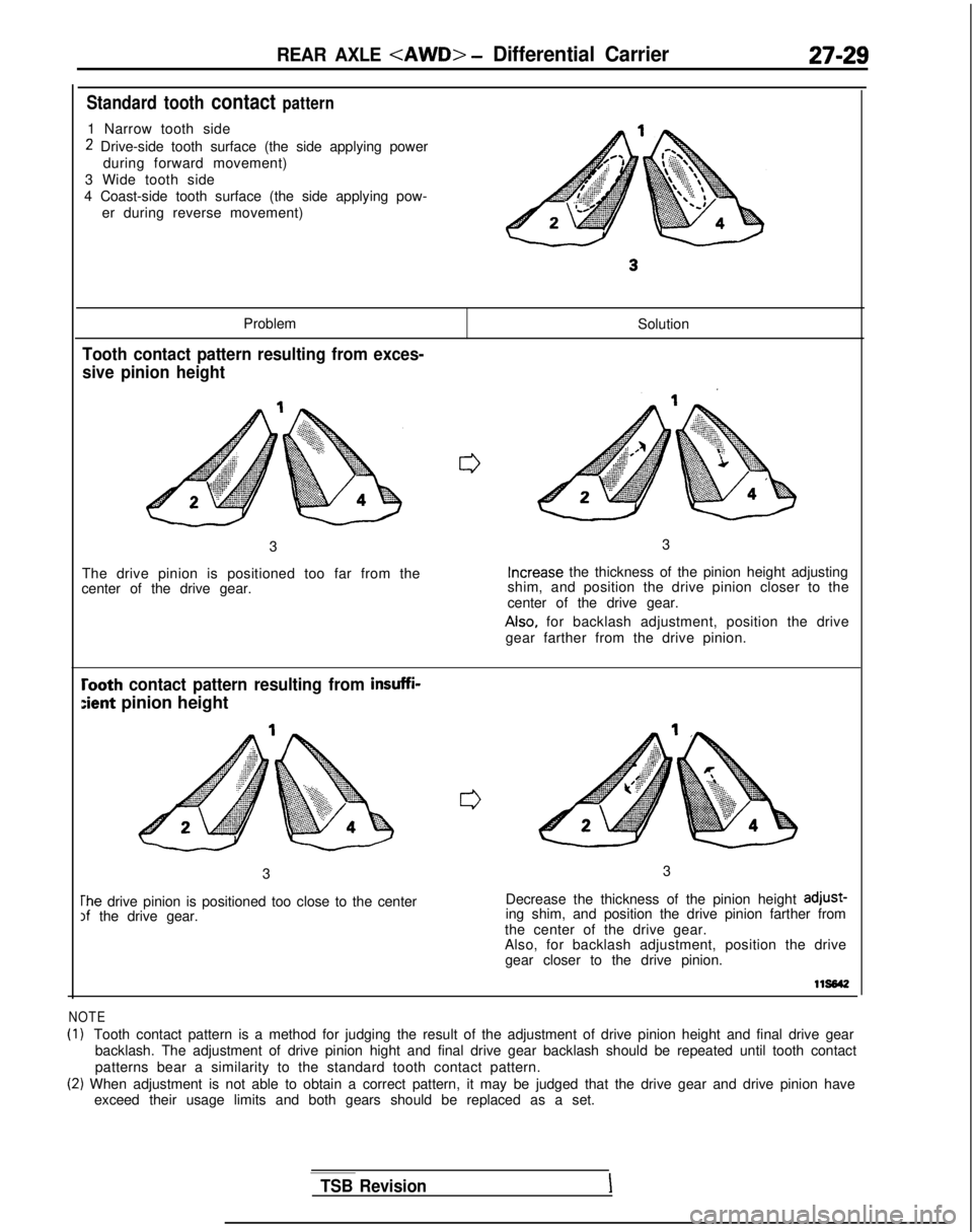
Standard tooth contact pattern
1 Narrow tooth side
2 Drive-side tooth surface (the side applying powerduring forward movement)
3 Wide tooth side
4 Coast-side tooth surface (the side applying pow- er during reverse movement)
Problem
Tooth contact pattern resulting from exces-
sive pinion height
Solution
3
The drive pinion is positioned too far from the
center of the drive gear. 3Increase
the thickness of the pinion height adjusting
shim, and position the drive pinion closer to the
center of the drive gear. Also,
for backlash adjustment, position the drive
gear farther from the drive pinion.
rooth contact pattern resulting from insuffi-
:ient pinion height
3
The drive pinion is positioned too close to the centerIf the drive gear. 3
Decrease the thickness of the pinion height adjust-
ing shim, and position the drive pinion farther from
the center of the drive gear.
Also, for backlash adjustment, position the drive gear closer to the drive pinion.
lls642
NOTE
(1)Tooth contact pattern is a method for judging the result of the adjustme\
nt of drive pinion height and final drive gear
backlash. The adjustment of drive pinion hight and final drive gear back\
lash should be repeated until tooth contact
patterns bear a similarity to the standard tooth contact pattern.
(2) When adjustment is not able to obtain a correct pattern, it may be judg\
ed that the drive gear and drive pinion have exceed their usage limits and both gears should be replaced as a set.
TSB RevisionI
Page 893 of 1273
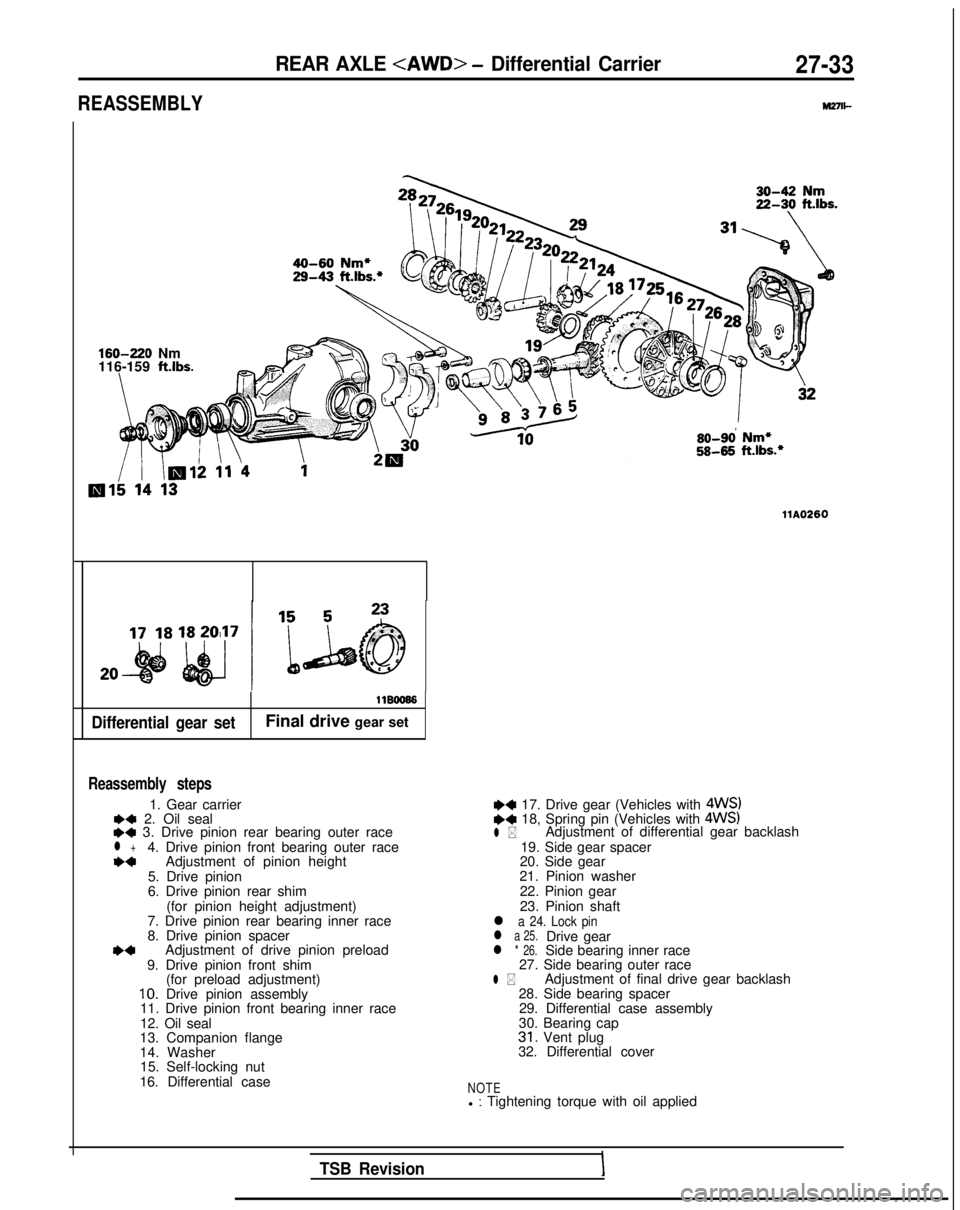
REASSEMBLY
REAR AXLE
M27n-
160-220
Nm
116-159
ft.lbs.
Differential gear set
11BOO66
Final drive gear set
Reassembly steps
1. Gear carrier*a 2. Oil seal++ 3. Drive pinion rear bearing outer racel +4. Drive pinion front bearing outer race*aAdjustment of pinion height
5. Drive pinion
6. Drive pinion rear shim (for pinion height adjustment)
7. Drive pinion rear bearing inner race
8. Drive pinion spacer
*aAdjustment of drive pinion preload
9. Drive pinion front shim (for preload adjustment)
10. Drive pinion assembly
11. Drive pinion front bearing inner race
12. Oil seal
13. Companion flange
14. Washer 15. Self-locking nut
16. Differential case so-9d
Nm*
5845
ft.lbs.*
llA0260
~~ 17. Drive gear (Vehicles with 4WS)e+ 18, Spring pin (Vehicles with 4WS)l *Adjustment of differential gear backlash
19. Side gear spacer
20. Side gear
21. Pinion washer
22. Pinion gear
23. Pinion shaft
l a 24. Lock pinl a 25.Drive gearl * 26.Side bearing inner race
27. Side bearing outer race
l *Adjustment of final drive gear backlash
28. Side bearing spacer 29. Differential case assembly
30. Bearing cap
31. Vent plug
32. Differential cover
NOTEl : Tightening torque with oil applied
TSB RevisionI