MITSUBISHI GALANT 1989 Service Repair Manual
Manufacturer: MITSUBISHI, Model Year: 1989, Model line: GALANT, Model: MITSUBISHI GALANT 1989Pages: 1273, PDF Size: 37.62 MB
Page 131 of 1273
ENGINE
f”.53A51b;m
r----v 1
3
lo-12 Nm
11-16
ftlbs.80-100
Nm y~x-di
58-72ft.lbs.2234!?!I
212543-55Nm 31-40, ff.lbs.b&-.,\‘-
/20-27 Nm
14-20
ftlbs.110;130 Nm80-94
ftlbs.
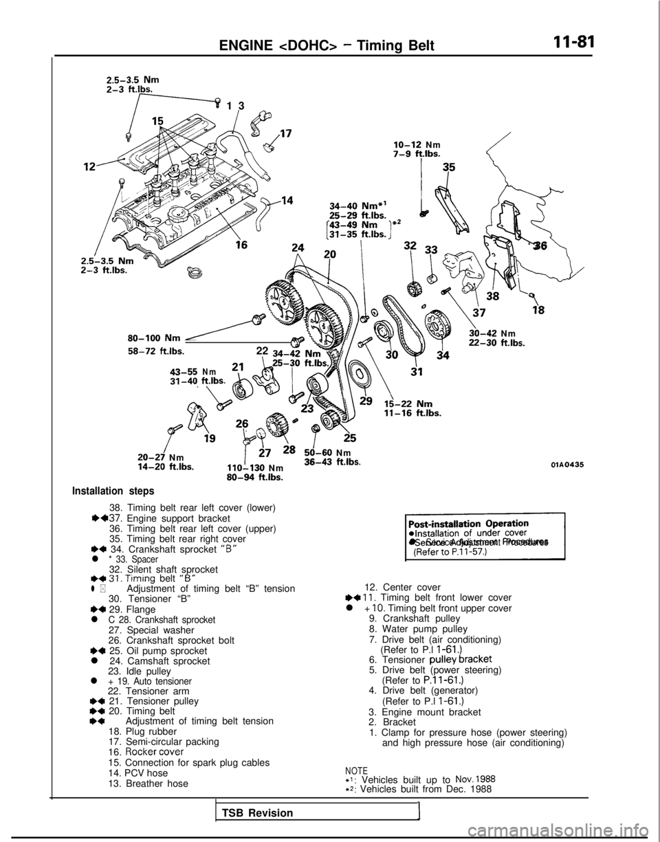
Installation steps
38. Timing belt rear left cover (lower)1H37. Engine support bracket
36. Timing belt rear left cover (upper)
35. Timing belt rear right cover
+4 34. Crankshaft sprocket “B”l * 33. Spacer32. Silent shaft sprocketI)+ 31. Timing
belt “B”l *Adjustment of timing belt “B” tension
30. Tensioner “B”
~~ 29. Flangel C 28. Crankshaft sprocket27. Special washer
26. Crankshaft sprocket bolt
~~ 25. Oil pump sprocket
l 24. Camshaft sprocket 23. Idle pulley
l + 19. Auto tensioner22. Tensioner arm+a 21. Tensioner pulley*C 20. Timing beltI)*Adjustment of timing belt tension
18. Plug rubber
17. Semi-circular packing
16.
Rocker cover
15. Connection for spark plug cables
14. PCV hose
13. Breather hose
!_-;
‘3
6
\
3,“”
30-42 Nm22-30 ftlbs.
125
50-60 Nm36-43 ftlbs.OlA0435
sl Service Adjustment Procedures
12. Center cover~~ 11, Timing belt front lower cover
l + IO. Timing belt front upper cover
9. Crankshaft pulley
8. Water pump pulley
7. Drive belt (air conditioning) (Refer to P.l
I-61 .)6. Tensioner pulley bracket
5. Drive belt (power steering)
(Refer to
P.ll-61.)4. Drive belt (generator)
(Refer to P.l
I-61 .)3. Engine mount bracket
2. Bracket1. Clamp for pressure hose (power steering) and high pressure hose (air conditioning)
NOTE+I: Vehicles built up to NOV. 1988+2: Vehicles built from Dec. 1988
TSB Revision I
Page 132 of 1273
II-82
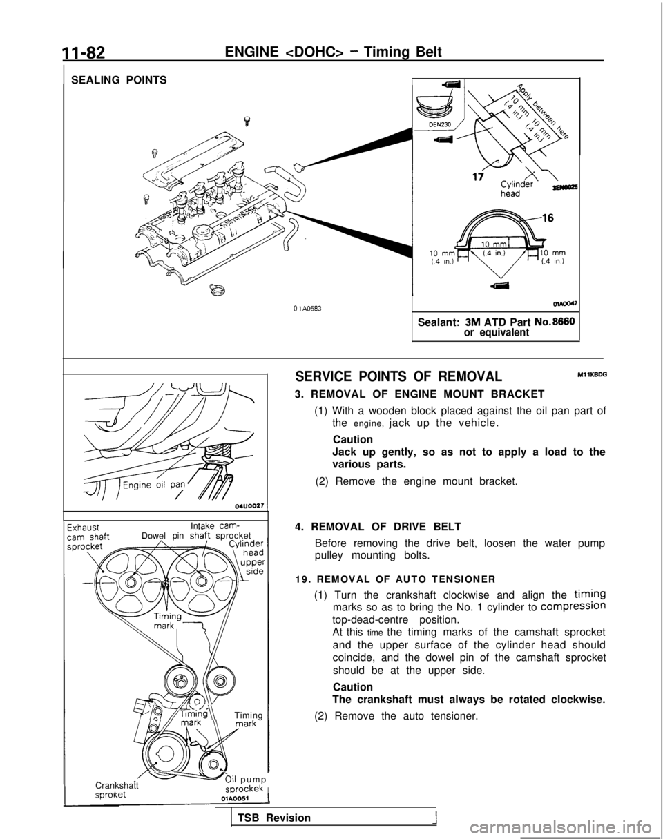
SEALING POINTSENGINE
- Timing Belt
olaoo4~
0 1 A0583
Sealant: 3M ATD Part No.8660
or equivalent 04UOO27
1
Intake cam-IDowel
pinshaft sprocket
/~~*;~i~g~\Timing 1
- .,ICrankshatt-Oil pum
p
,
_sprockekI sproKer
OlAOOSl
1
SERVICE POINTS OF REMOVALMl 1KBDG
3. REMOVAL OF ENGINE MOUNT BRACKET
(1) With a wooden block placed against the oil pan part ofthe engine, jack up the vehicle.
Caution
Jack up gently, so as not to apply a load to the
various parts.
(2) Remove the engine mount bracket.
4. REMOVAL OF DRIVE BELT Before removing the drive belt, loosen the water pump
pulley mounting bolts.
19. REMOVAL OF AUTO TENSIONER (1) Turn the crankshaft clockwise and align the
timing
marks so as to bring the No. 1 cylinder to compresslon
top-dead-centre position.
At this time the timing marks of the camshaft sprocket
and the upper surface of the cylinder head should
coincide, and the dowel pin of the camshaft sprocketshould be at the upper side.
Caution
The crankshaft must always be rotated clockwise.
(2) Remove the auto tensioner.
TSB Revision
1
Page 133 of 1273
ENGINE
1
r
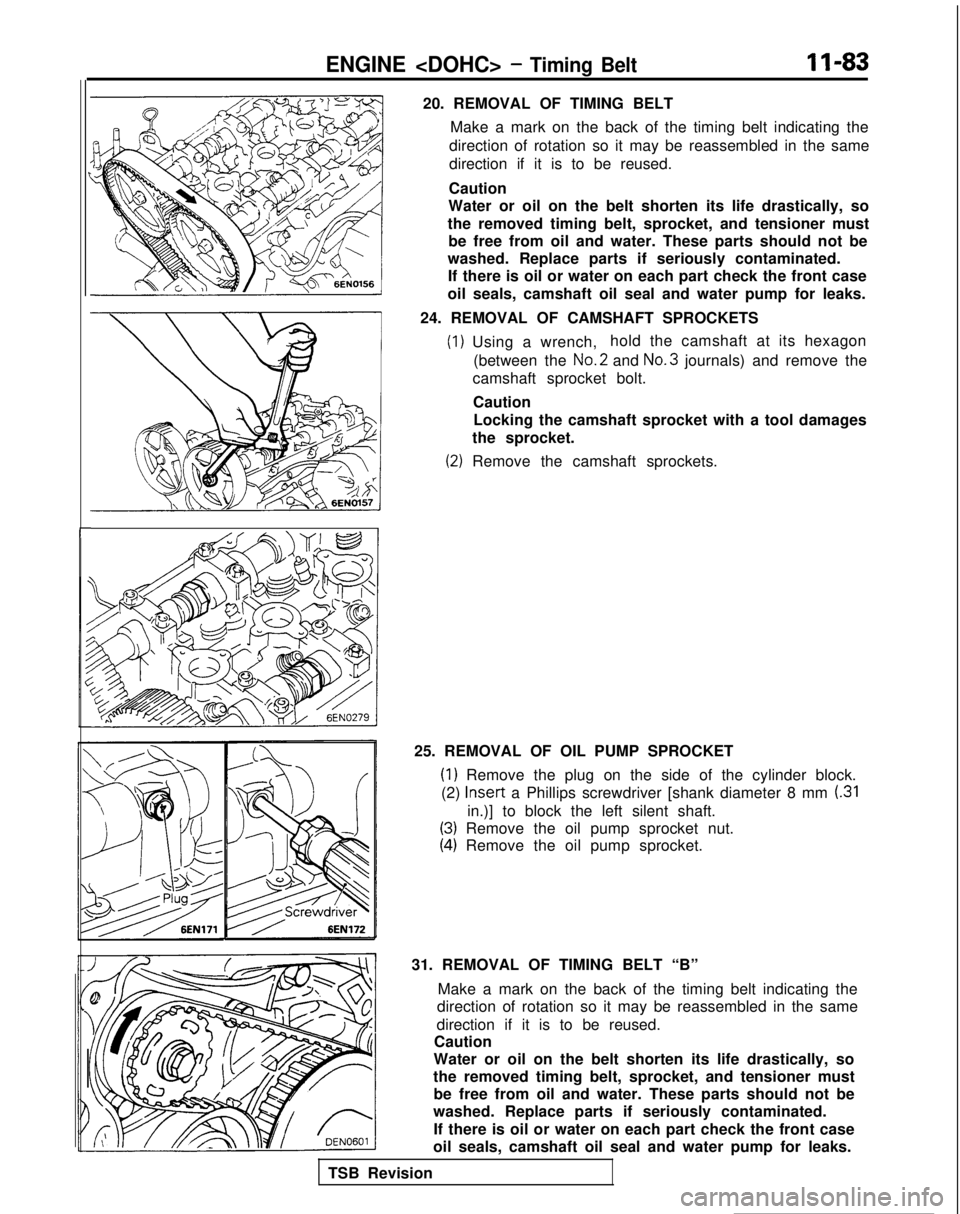
20. REMOVAL OF TIMING BELTMake a mark on the back of the timing belt indicating the
direction of rotation so it may be reassembled in the same
direction if it is to be reused.
Caution
Water or oil on the belt shorten its life drastically, so
the removed timing belt, sprocket, and tensioner must be free from oil and water. These parts should not be
washed. Replace parts if seriously contaminated. If there is oil or water on each part check the front case
oil seals, camshaft oil seal and water pump for leaks.
24. REMOVAL OF CAMSHAFT SPROCKETS
(1) Using a wrench, hold the camshaft at its hexagon
(between the No.2
and No.3
journals) and remove the
camshaft sprocket bolt.
CautionLocking the camshaft sprocket with a tool damages
the sprocket.
(2) Remove the camshaft sprockets.
25. REMOVAL OF OIL PUMP SPROCKET
(1) Remove the plug on the side of the cylinder block.
(2) Insert
a Phillips screwdriver [shank diameter 8 mm
(.31
in.)] to block the left silent shaft.
(3) Remove the oil pump sprocket nut.
(4) Remove the oil pump sprocket.
31. REMOVAL OF TIMING BELT “B” Make a mark on the back of the timing belt indicating the
direction of rotation so it may be reassembled in the same
direction if it is to be reused.
Caution
Water or oil on the belt shorten its life drastically, so
the removed timing belt, sprocket, and tensioner must be free from oil and water. These parts should not be
washed. Replace parts if seriously contaminated.
If there is oil or water on each part check the front case
oil seals, camshaft oil seal and water pump for leaks.
TSB Revision
Page 134 of 1273
11-84
ENGINE
QdiJ00°00B
rackCrack
Crack ’ 7EN207
Separation
Rounded belt side
Abnormal wear (fluffy canvas fiber)
7EN208
Rubber
exposed
Tooth
missing and
canvas fiber exposed
7EN209
6EN0159
Y
1
-
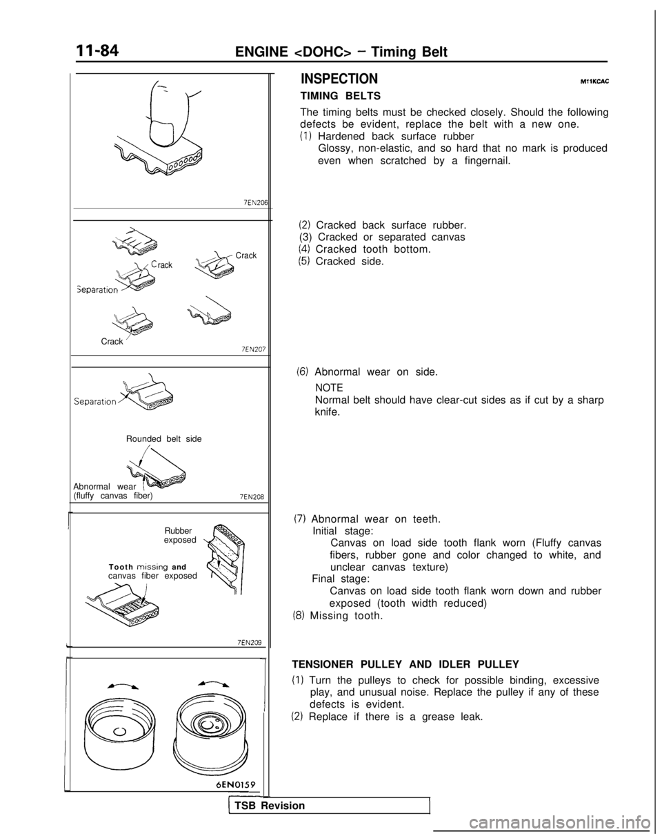
INSPECTION
TIMING BELTS MIlKCAC
The timing belts must be checked closely. Should the following
defects be evident, replace the belt with a new one.
(1) Hardened back surface rubber Glossy, non-elastic, and so hard that no mark is produced
even when scratched by a fingernail.
(2) Cracked back surface rubber.
(3) Cracked or separated canvas
(4) Cracked tooth bottom.
(5) Cracked side.
(6) Abnormal wear on side.
NOTE
Normal belt should have clear-cut sides as if cut by a sharp
knife.
(7) Abnormal wear on teeth. Initial stage: Canvas on load side tooth flank worn (Fluffy canvas
fibers, rubber gone and color changed to white, and unclear canvas texture)
Final stage:
Canvas on load side tooth flank worn down and rubber
exposed (tooth width reduced)
(8) Missing tooth.
TENSIONER PULLEY AND IDLER PULLEY
(1) Turn the pulleys to check for possible binding, excessive play, and unusual noise. Replace the pulley if any of these
defects is evident.
(2) Replace if there is a grease leak.
I1 TSB Revision
Page 135 of 1273
ENGINE
6EN0280
6EN0161
/6Ei40162
6
68
Plug
6EN0281 j
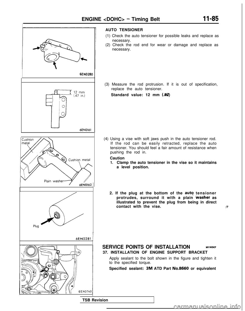
AUTO TENSIONER
(1) Check the auto tensioner for possible leaks and replace as necessary.
(2) Check the rod end for wear or damage and replace as necessary.
(3) Measure the rod protrusion. If it is out of specification, replace the auto tensioner.
Standard value: 12 mm (.47 in.)
(4) Using a vise with soft jaws push in the auto tensioner rod. If the rod can be easily retracted, replace the auto
tensioner. You should feel a fair amount of resistance when
pushing the rod in.
Caution
1.Clamp the auto tensioner in the vise so it maintains
a level position.
2. If the plug at the bottom of the auto
tensioner
protrudes, surround it with a plain
Lvasher as
illustrated to prevent the plug from being in direct
contact with the vise.
SERVICE POINTS OF INSTALLATION MllKDCF
37. INSTALLATION OF ENGINE SUPPORT BRACKET
Apply sealant to the bolt shown in the figure and tighten it
to the specified torque.
Specified sealant:
3M ATD Part No.8660 or equivalent
TSB Revision
Page 136 of 1273
11-86
ENGINE
Crankshaft
sprocket “B”
Crankshaft
6EN304 j
Spacer
I
ChamferedSilent shaft n
sprocket
I
Center oftenslonerpulley
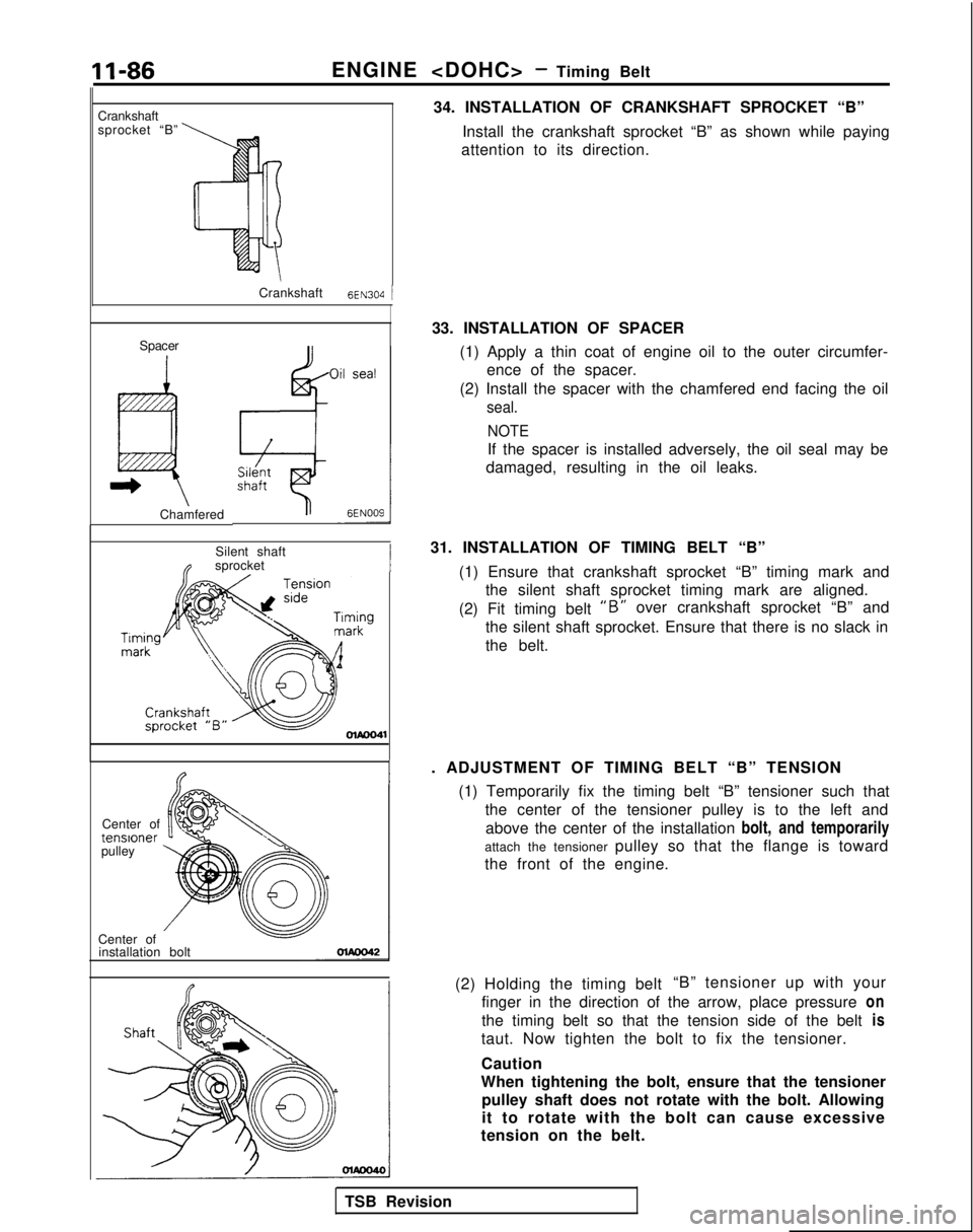
Center of installation bolt 34. INSTALLATION OF CRANKSHAFT SPROCKET “B”
Install the crankshaft sprocket “B” as shown while paying
attention to its direction.
33. INSTALLATION OF SPACER (1) Apply a thin coat of engine oil to the outer circumfer-ence of the spacer.
(2) Install the spacer with the chamfered end facing the oil
seal.
NOTE
If the spacer is installed adversely, the oil seal may be
damaged, resulting in the oil leaks.
31. INSTALLATION OF TIMING BELT “B” (1) Ensure that crankshaft sprocket “B” timing mark andthe silent shaft sprocket timing mark are aligned.
(2) Fit timing belt
“B” over crankshaft sprocket “B” and
the silent shaft sprocket. Ensure that there is no slack in
the belt.
. ADJUSTMENT OF TIMING BELT “B” TENSION (1) Temporarily fix the timing belt “B” tensioner such thatthe center of the tensioner pulley is to the left andabove the center of the installation bolt, and temporarily
attach the tensioner pulley so that the flange is toward
the front of the engine.
(2) Holding the timing belt “B” tensioner up with your
finger in the direction of the arrow, place pressure on
the timing belt so that the tension side of the belt is
taut. Now tighten the bolt to fix the tensioner.
Caution
When tightening the bolt, ensure that the tensioner pulley shaft does not rotate with the bolt. Allowing
it to rotate with the bolt can cause excessive
tension on the belt.
TSB Revision
Page 137 of 1273
.
ENGINE
installation bolt ~~~-
Crankshaft
sprocket “B”
/
Crankshaft /\ \
sprocket Flange Crankshaft 6~~272
6EN172I
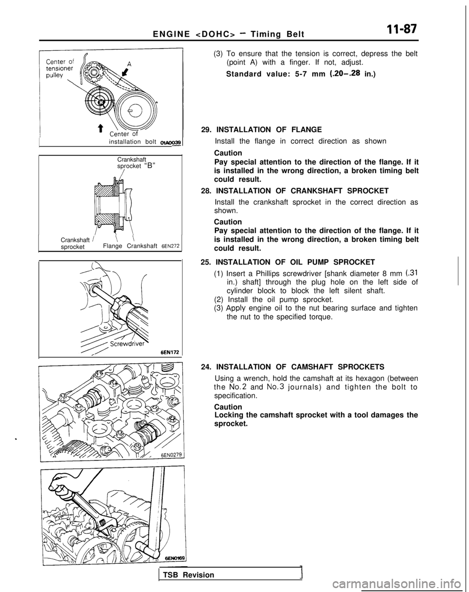
(3) To ensure that the tension is correct, depress the belt
(point A) with a finger. If not, adjust.
Standard value: 5-7 mm
(.20-.28 in.)
29. INSTALLATION OF FLANGE Install the flange in correct direction as shown
Caution Pay special attention to the direction of the flange. If it
is installed in the wrong direction, a broken timing belt
could result.
28. INSTALLATION OF CRANKSHAFT SPROCKET Install the crankshaft sprocket in the correct direction as
shown.
Caution Pay special attention to the direction of the flange. If it
is installed in the wrong direction, a broken timing belt
could result.
25. INSTALLATION OF OIL PUMP SPROCKET (1) Insert a Phillips screwdriver [shank diameter 8 mm
(.31
in.) shaft] through the plug hole on the left side of
cylinder block to block the left silent shaft.
(2) Install the oil pump sprocket.
(3)
apply engine oil to the nut bearing surface and tighten
the nut to the specified torque.
24. INSTALLATION OF CAMSHAFT SPROCKETS Using a wrench, hold the camshaft at its hexagon (between
the No.2
and No.3
journals) and tighten the bolt to
specification.
Caution Locking the camshaft sprocket with a tool damages the
sprocket.
TSB Revision
Page 138 of 1273
ENGINE
6
@
Plug
6EN0281
Center bolt :
6EN026:-
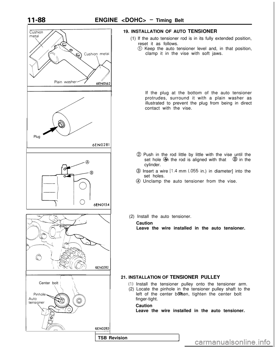
19. INSTALLATION OF AUTO TENSIONER
(1) If the auto tensioner rod is in its fully extended position, reset it as follows.
@I Keep the auto tensioner level and, in that position,clamp it in the vise with soft jaws.
If the plug at the bottom of the auto tensioner
protrudes, surround it with a plain washer as illustrated to prevent the plug from being in direct
contact with the vise.
@ Push in the rod little by little with the vise until the set hole @ in the rod is aligned with that
@I in the
cylinder.
@ Insert a wire Il.4 mm (055 in.) in diameter] into the
set holes.
@I Unclamp the auto tensioner from the vise.
(2) Install the auto tensioner. CautionLeave the wire installed in the auto tensioner.
21. INSTALLATION OF TENSIONER PULLEY
(1) Install the tensioner pulley onto the tensioner arm.
(2) Locate the pinhole in the tensioner pulley shaft to the left of the center bolt. Then, tighten the center bolt
finger-tight.
Caution
Leave the wire installed in the auto tensioner.
TSB Revision
I
Page 139 of 1273
ENGINE
Camshaft sprocket
Top surface of
cylinder head
/b*TJ,$
:-; /
e
\I’ \ii)’
Timing mark
6EN028L
--.-./Dowel pin
Timing mark
6EN0304
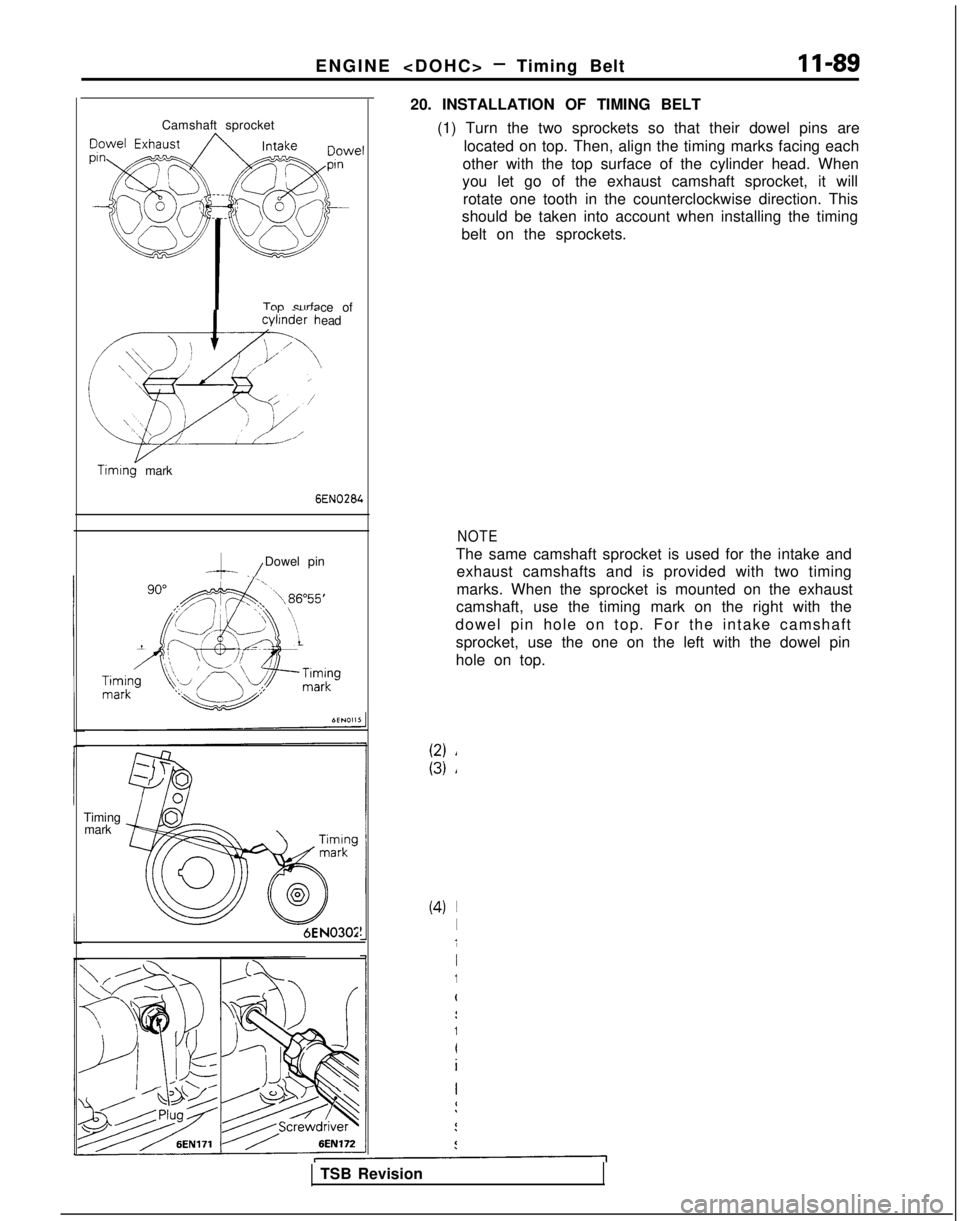
20. INSTALLATION OF TIMING BELT
(1) Turn the two sprockets so that their dowel pins arelocated on top. Then, align the timing marks facing each
other with the top surface of the cylinder head. When
you let go of the exhaust camshaft sprocket, it will
rotate one tooth in the counterclockwise direction. This
should be taken into account when installing the timing
belt on the sprockets.
NOTE
The same camshaft sprocket is used for the intake and exhaust camshafts and is provided with two timing
marks. When the sprocket is mounted on the exhaust
camshaft, use the timing mark on the right with the
dowel pin hole on top. For the intake camshaft sprocket, use the one on the left with the dowel pin
hole on top.
TSB Revision
Page 140 of 1273
II-90ENGINE
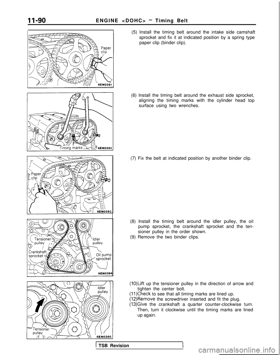
(5) Install the timing belt around the intake side camshaft sprocket and fix it at indicated position by a spring typepaper clip (binder clip).
(6) Install the timing belt around the exhaust side sprocket, aligning the timing marks with the cylinder head top
surface using two wrenches.
(7) Fix the belt at indicated position by another binder clip.
(8) Install the timing belt around the idler pulley, the oil pump sprocket, the crankshaft sprocket and the ten-
sioner pulley in the order shown.
(9) Remove the two binder clips.
(1O)Lift up the tensioner pulley in the direction of arrow and
tighten the center bolt.
(11)Check to see that all timing marks are lined up. (12)Remove
the screwdriver inserted and fit the plug.
(13)Give the crankshaft a quarter counter-clockwise turn.
Then, turn it clockwise until the timing marks are lined up again.
1 TSB Revision