MITSUBISHI GALANT 1989 Service Repair Manual
Manufacturer: MITSUBISHI, Model Year: 1989, Model line: GALANT, Model: MITSUBISHI GALANT 1989Pages: 1273, PDF Size: 37.62 MB
Page 151 of 1273
FUEL SYSTEM
13-9
r
I Connector
6FU1216
EXPLANATION AND PRECAUTION RELATED TO
HARNESS CHECKING
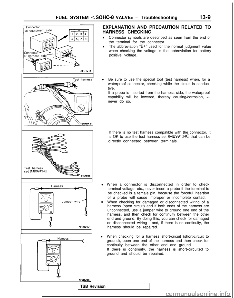
l Connector symbols are described as seen from the end of
the terminal for the connector.
lThe abbreviation “B+”
used for the normal judgment value
when checking the voltage is the abbreviation for battery positive voltage.
Test harness
set (MB991348)
Jumper wire
&6FU1217
Harness <
LQ
Q,
6FUlZlBj
l
Be sure to use the special tool (test harness) when, for a
waterproof connector, checking while the circuit is conduc-
tive. If a probe is inserted from the harness side, the waterproof
capability will be lowered, thereby causing/corrosion, SO
never do so.
If there is no test harness compatible with the connector, it
is OK to use the test harness set (MB991348)
that can be
directly connected between terminals.
l When a connector is disconnected in order to check terminal voltage, etc., never insert a probe if the terminal to
be checked is a female pin, because the forceful insertion
of a probe will cause improper or incomplete contact.
l When checking for damaged or disconnected wiring of a
harness (open circuit) and if both ends of the harness are
unconnected, use a jumper wire to ground one end of the
harness, and then check for continuity between the other
end and ground. By doing this, you can check for damaged
or disconnected wiring
., and, if there is no continuity, the
harness should be repaired.
l When checking for a harness short-circuit (short-circuit to
ground), open one end of the harness and then check for
continuity between the other end and ground.
If there is continuity, the harness is short-circuited to
ground and should be repaired.
TSB Revision
Page 152 of 1273
13-10
FUEL SYSTEM
at sensor side
1\~“‘,““W,O,’ ‘\*N 4-cnDQ5a,, \llllf,,
c 3 c-11 ‘.<-!
( .[&
;%* \ g ~ &.$$~&%,;
0%: E
.Oj-,,
giI lOWI -,n
/ ~ ( ~~‘-~~~
-.mo .u. m,.0 - rj*> ;;
indicator lamp68AOO93
l
If the voltage (power-supply voltage) supplied to a sensor
is not normal, repair the harness. If the voltage to the sensor is still not normal after the har-
ness has been repaired, repalce the engine control module
and check again.
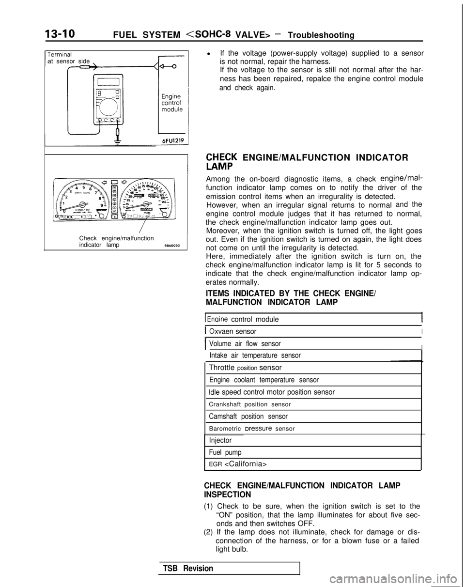
W&K ENGINE/MALFUNCTION INDICATOR
Among the on-board diagnostic items, a check
engine/mal-
function indicator lamp comes on to notify the driver of the
emission control items when an irregurality is detected. However, when an irregular signal returns to normal
andthe
engine control module judges that it has returned to normal,
the check engine/malfunction indicator lamp goes out. Moreover, when the ignition switch is turned off, the light goes
out. Even if the ignition switch is turned on again, the light does not come on until the irregularity is detected.
Here, immediately after the ignition switch is turn on, the
check engine/malfunction indicator lamp is lit for 5 seconds to indicate that the check engine/malfunction indicator lamp op-
erates normally.
ITEMS INDICATED BY THE CHECK ENGINE/
MALFUNCTION INDICATOR LAMP
1 Enaine control module
IOxvaen sensorI
IVolume air flow sensorIIntake air temperature sensor
Throttle position sensor
Engine coolant temperature sensor
Idle speed control motor position sensor
Crankshaft position sensor
Camshaft position sensor
Barometric rxessure sensor
Injector
Fuel pump
EGR
CHECK ENGINE/MALFUNCTION INDICATOR LAMP
INSPECTION
(1) Check to be sure, when the ignition switch is set to the “ON” position, that the lamp illuminates for about five sec-onds and then switches OFF.
(2) If the lamp does not illuminate, check for damage or dis-
connection of the harness, or for a blown fuse or a failedlight bulb.
TSB Revision
Page 153 of 1273
FUEL SYSTEM
ON-BOARD DIAGNOSTIC-
The engine control module monitors the input/out-
put signals (some signals at all times and the others
under specified conditions) of the engine control
module.
When it is noticed that an irregularity has continued
for a specified time or longer from when the irregu- lar signal is initially monitored, passing a certain
number, the engine control module judges that an
irregularity has occurred, memorizes the diagnostic
trouble code, and outputs the signal to the on-board
diagnostic output terminal.
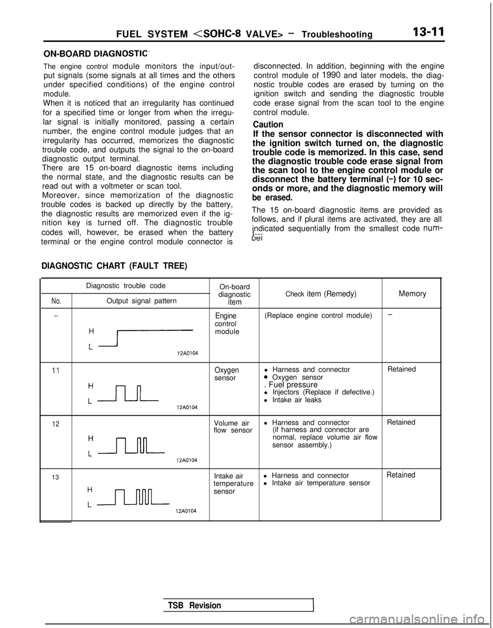
There are 15 on-board diagnostic items including
the normal state, and the diagnostic results can be
read out with a voltmeter or scan tool.
Moreover, since memorization of the diagnostic
trouble codes is backed up directly by the battery,
the diagnostic results are memorized even if the ig- nition key is turned off. The diagnostic trouble
codes will, however, be erased when the battery disconnected. In addition, beginning with the engine
control module of
1990 and later models, the diag-
nostic trouble codes are erased by turning on the
ignition switch and sending the diagnostic trouble
code erase signal from the scan tool to the engine
control module.
Caution
If the sensor connector is disconnected with
the ignition switch turned on, the diagnostic
trouble code is memorized. In this case, send
the diagnostic trouble code erase signal from
the scan tool to the engine control module or disconnect the battery terminal (-)
for 10 sec-
onds or more, and the diagnostic memory will
be erased.
The 15 on-board diagnostic items are provided as
follows, and if plural items are activated, they are all
indicated sequentially from the smallest code num-
I---
terminal or the engine control module connector is
uer
DIAGNOSTIC CHART (FAULT TREE)
No.
-
Diagnostic trouble code On-board
diagnostic
Check item (Remedy) MemoryOutput signal patternitem
-Engine(Replace engine control module)
control
:r
module 12A0104
11Oxygenl Harness and connector
Retained
sensor0 Oxygen sensor
:-JLJ--
. Fuel pressure
l Injectors (Replace if defective.)
l Intake air leaks 12A0104
12Volume air
l Harness and connector
Retained
flow sensor (if harness and connector are
:-JJ-M-
normal, replace volume air flow
sensor assembly.) 12A0104
13 Intake air
l Harness and connector
Retained
temperature l Intake air temperature sensor
:n
sensor 12A0104
TSB Revision
Page 154 of 1273
13-12
FUEL SYSTEM
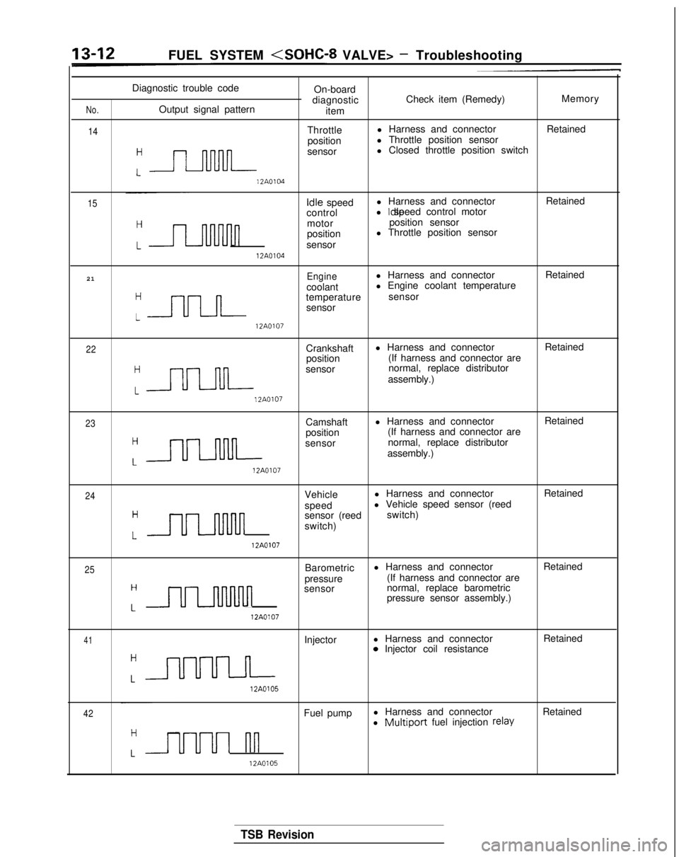
No.
14
Diagnostic trouble code
On-board
diagnostic Check item (Remedy)
Memory
Output signal pattern item
Throttle l Harness and connector
Retained
position l Throttle position sensor
:-
sensor l Closed throttle position switch 12A0104
15
Idle
speed l Harness and connector
Retained
control l Idle speed control motor
n
motor
position sensor
position l Throttle position sensor
sensor 12A0104
21
Enginel Harness and connector Retained
coolant l Engine coolant temperature
“=
temperature
sensor
sensor 12A0107
22Crankshaft
l Harness and connector
Retained
position (If harness and connector are
:-
sensor normal, replace distributor
assembly.) 12A0107
23Camshaft
l Harness and connector
Retained
position (If harness and connector are
:=
sensor normal, replace distributor
assembly.) 12A0107
24Vehicle
l Harness and connector
Retained
speed l Vehicle speed sensor (reed
H
uulnnn
sensor (reed
switch)
switch)
L 12A0107
25Barometric
l Harness and connector
Retained
pressure (If harness and connector are
H
ULnMnn
sensor
normal, replace barometric
pressure sensor assembly.)
L 12A0107
41Injector
l Harness and connector
Retained0 Injector coil resistance
:a 12A0105
42Fuel pump
l Harness and connector
Retained
l Multiport fuel injection relay
Luuul nn
12A0105
TSB Revision
Page 155 of 1273
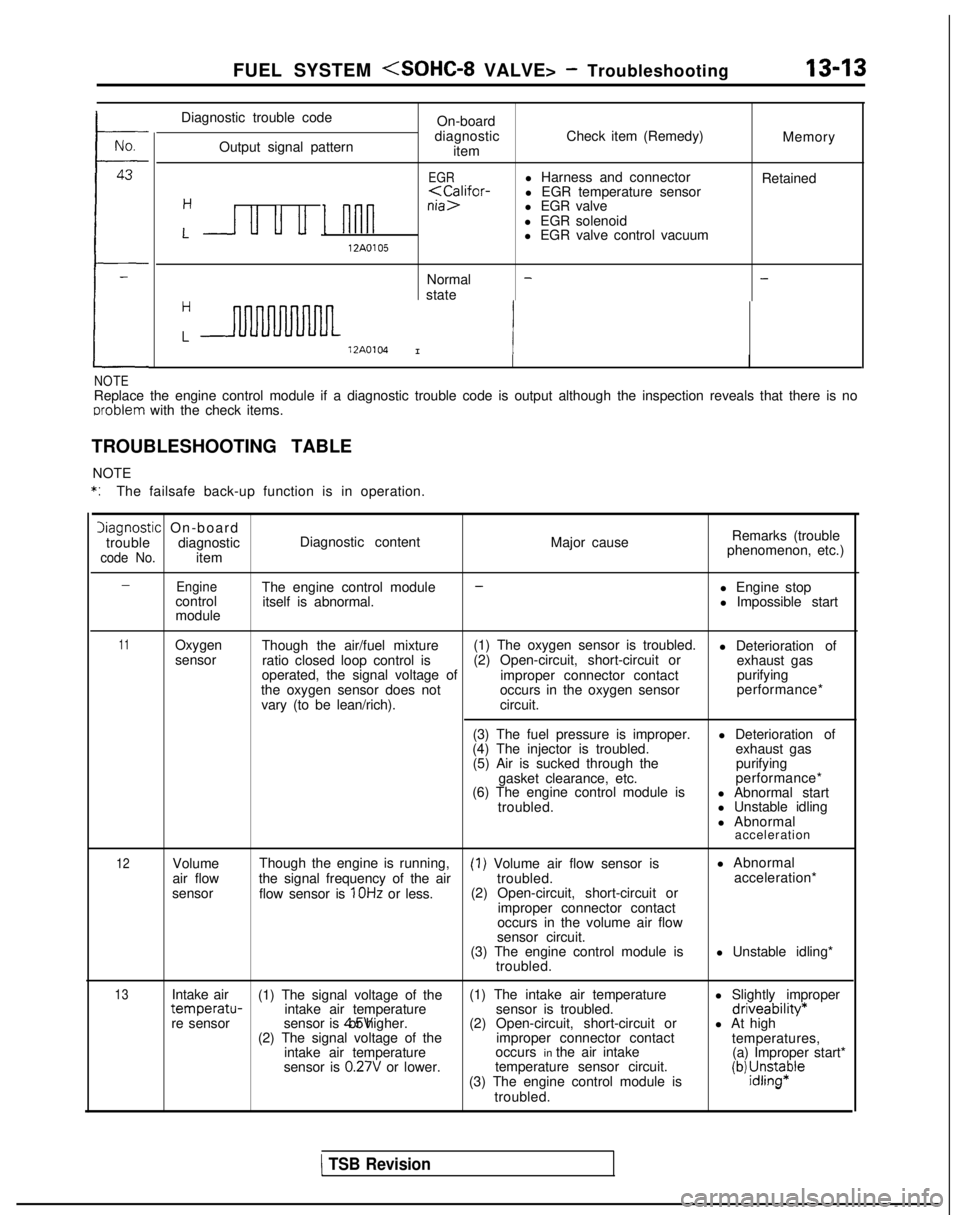
FUEL SYSTEM
No.
43
4
-
Diagnostic trouble code
Output signal pattern On-board
diagnostic item Check item (Remedy)
Memory
EGRl Harness and connector
Retained
l EGR solenoid
L u u u I nnnl EGR valve control vacuum12A0105
Normal -state
-
H
L12A0104I 1
NOTEReplace the engine control module if a diagnostic trouble code is output\
although the inspection reveals that there is no
oroblem
with the check items.
TROUBLESHOOTING TABLE NOTE
*:The failsafe back-up function is in operation.
Diagnostic On-board
trouble diagnostic Diagnostic content
code No.item Major cause
Remarks (trouble
phenomenon, etc.)
-EngineThe engine control module-l Engine stop
control itself is abnormal. l Impossible start
module
11Oxygen Though the air/fuel mixture (1) The oxygen sensor is troubled.
l Deterioration of
sensor ratio closed loop control is (2) Open-circuit, short-circuit or
exhaust gas
operated, the signal voltage of improper connector contactpurifying
the oxygen sensor does not occurs in the oxygen sensorperformance*
vary (to be lean/rich). circuit.
(3) The fuel pressure is improper. l Deterioration of
(4) The injector is troubled. exhaust gas
(5) Air is sucked through the purifying
gasket clearance, etc. performance*
(6) The engine control module is l Abnormal start
troubled. l Unstable idling
l Abnormal
acceleration
12Volume
air flow
sensor Though the engine is running,(I) Volume air flow sensor is
l Abnormal
the signal frequency of the air troubled.acceleration*
flow sensor is
1 OHz or less. (2) Open-circuit, short-circuit or
improper connector contact
occurs in the volume air flow
sensor circuit.
(3) The engine control module is l Unstable idling*
troubled.
13Intake air (1) The signal voltage of the (1) The intake air temperature
l Slightly impropertemperatu-intake air temperaturesensor is troubled.driveability*re sensorsensor is 4.5V or higher.
(2) Open-circuit, short-circuit or l At high
(2) The signal voltage of the improper connector contact
temperatures,
intake air temperature occurs in the air intake
(a) Improper start*
sensor is
0.27V or lower. temperature sensor circuit.
(3) The engine control module is(b) ;J;pe
troubled.
1 TSB Revision
Page 156 of 1273
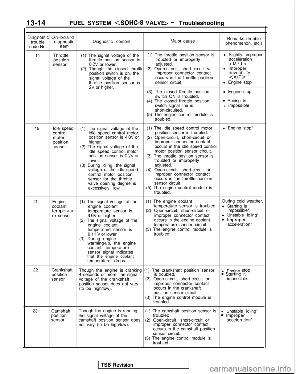
13-14
FUEL SYSTEM
Iiagnostic On-boar
d
trouble diagnostic Diagnostic content Major causeRemarks (trouble
phenomenon, etc.)
code No. item
14Throttle
(1) The signal voltage of the (1) The throttle position sensor is
l Slightly improper
position throttle position sensor is troubled or improperly
acceleration
sensor
0.2V or lower. adjusted.
(2) Though the closed throttle (2) Open-circuit, short-circuit Orl Improper
position switch is on, the improper connector contact
signal voltage of the occurs in the throttle position
d$eybzty
throttle position sensor is
sensor circuit.
l Engine stop2V or higher.
(3) The closed throttle position l Engine stop
switch ON is troubled.
(4) The closed throttle position
0 Racing is
switch signal line ist impossible
short-circuited.
(5) The engine control module is
troubled.
15Idle speed (1) The signal voltage of the (1) The idle speed control motor
l Engine stop*
control idle speed control motor position sensor is troubled.
motor position sensor is
4.8V or
(2) Open-circuit, short-circuit or
position higher. improper connector contact
sensor (2) The signal voltage of the occurs in the idle speed control
idle speed control motor motor position sensor circuit.
position sensor is
0.2V or (3) The throttle position sensor is
lower. troubled or improperly
(3) During idling, the signal adjusted.
voltage of the idle speed (4) Open-circuit, short-circuit or
control motor position improper connector contact
sensor for the throttle occurs in the throttle position
valve opening degree is sensor circuit.
excessively low. (5) The engine control module is
troubled.
21Engine (1) The signal voltage of the (1) The engine coolant
During cold weather,
coolant engine coolant temperature sensor is troubled.
l Starting is
temperatu-temperature sensor is(2) Open-circuit, short-circuit or
impossible*.
re sensor4.6V or higher. improper connector contact
l Unstable idling*
(2) The signal voltage of the occurs in the engine coolant0 Improper
engine coolant temperature sensor circuit. acceleration*
temperature sensor is (3) The engine control module is
0.11
V or lower. troubled.
(3) During engine warming-up, the engine
coolant temperature
sensor signal indicates
that the engine coolant
temperature drops.
22Crankshaft Though the engine is cranking (1) The crankshaft position sensor
l Engine stop
position 4 seconds or more, the signal is troubled.0 Startrng 1s
sensor
voltage of the crankshaft (2) Open-circuit, short-circuit or
impossible.
position sensor does not vary improper connector contact
(to be high/low). occurs in the crankshaft
position sensor circuit.
(3) The engine control module is troubled.
23Camshaft Though the engine is running,
(1) The camshaft position sensor is
l Unstable idling*
position the signal voltage of the troubled.0 Improper
sensor camshaft position sensor does (2) Open-circuit, short-circuit or acceleration*
not vary (to be high/low). improper connector contact
occurs in the camshaft position
sensor circuit.
(3) The engine control module is troubled.
TSB Revision
Page 157 of 1273
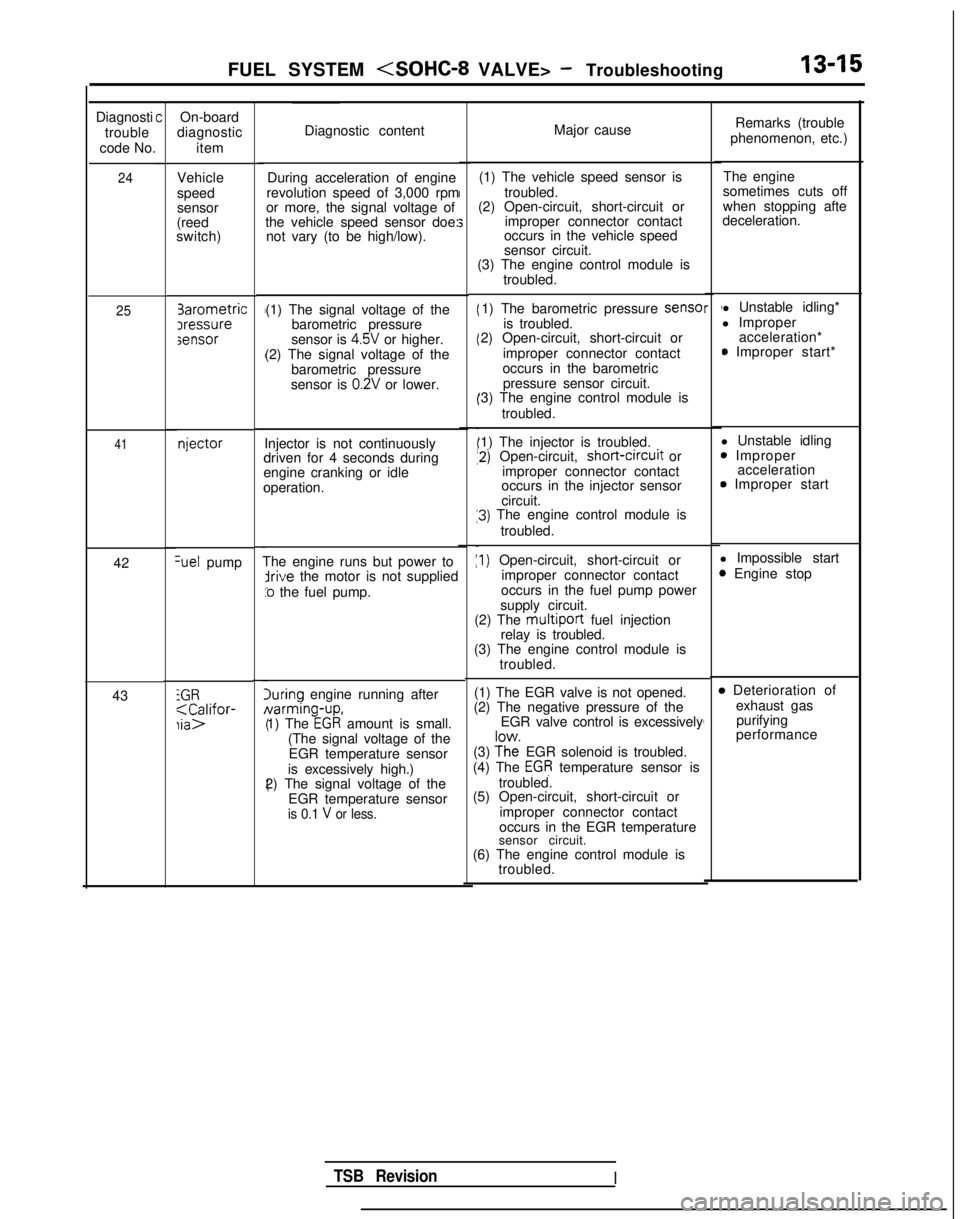
FUEL SYSTEM
Diagnosti
trouble
code No.
24
25
41
42Set pump
43
iGR;aC;lifor-
COn-board
diagnostic
item
Vehicle
speed
sensor
(reed
switch) 3arometric
Iressuresensor
njector
Diagnostic content
Major cause
During acceleration of engine
revolution speed of 3,000 rpm
or more, the signal voltage of
the vehicle speed sensor doe: not vary (to be high/low). (1) The vehicle speed sensor is
troubled.
(2) Open-circuit, short-circuit or
improper connector contact
occurs in the vehicle speed
sensor circuit.
(1) The signal voltage of the barometric pressure
sensor is 4.5V or higher.
(2) The signal voltage of the barometric pressure
sensor is
0.2V or lower.
Injector is not continuously
driven for 4 seconds during
engine cranking or idle
operation.
The engine runs but power to
irive the motor is not supplied
:o the fuel pump.
luring engine running after Narming-up,
1) The
EGR amount is small.
(The signal voltage of the EGR temperature sensor
is excessively high.)
2) The signal voltage of the
EGR temperature sensor
is 0.1 V or less.
(3) The engine control module is troubled.
1) The barometric pressure sense
is troubled.
2) Open-circuit, short-circuit or
improper connector contact
occurs in the barometric pressure sensor circuit.
‘3) The engine control module is
troubled.
‘1) The injector is troubled.
12) Open-circuit, short-crrcuit
or
improper connector contact
occurs in the injector sensor
circuit.
13) The engine control module is
troubled.
:I) Open-circuit, short-circuit or improper connector contact
occurs in the fuel pump power
supply circuit.
(2) The
multiport fuel injection
relay is troubled.
(3) The engine control module is
troubled.
(1) The EGR valve is not opened.
(2) The negative pressure of the EGR valve control is excessively
(3)
?h”e EGR solenoid is troubled.
(4) The EGR temperature sensor is
troubled.
(5) Open-circuit, short-circuit or
improper connector contact
occurs in the EGR temperature
sensor circuit.
(6) The engine control module is troubled.
r 1l Unstable idling*
l Improper acceleration*
0 Improper start*
l Unstable idling
0 Improper acceleration
0 Improper start
l Impossible start
3 Engine stop4
4
,
B Deterioration of exhaust gaspurifying
performance
Remarks (trouble
phenomenon, etc.)
The engine
sometimes cuts off
when stopping afte
deceleration.
TSB RevisionI
Page 158 of 1273
13-16
FUEL SYSTEM
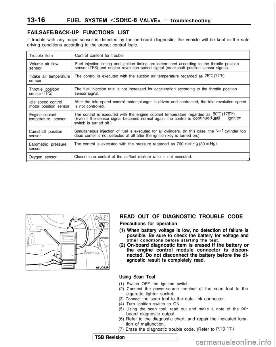
FAILSAFE/BACK-UP FUNCTIONS LIST
If trouble with any major sensor is detected by the on-board diagnostic,\
the vehicle will be kept in the safe
driving conditions according to the preset control logic.
Trouble item Control content for trouble
Volume air flow Fuel injection timing and ignition timing are determined according to th\
e throttle position
sensor sensor
(TPS) and engine revolution speed signal (crankshaft position sensor signal)\
.
Intake air temperature The control is executed with the suction air temperature regarded as
25°C (77°F).
sensor
Throttle position The fuel injection rate is not increased for acceleration according to t\
he throttle position
sensor
(TPS)sensor signal.
Idle speed control After the idle speed control motor plunger is driven and contracted, the\
idle revolution speed
motor position sensor is not controlled.
Engine coolant The control is executed with the engine coolant temperature regarded as \
8OO.C (176°F).temperature sensor (Even if the sensor signal becomes normal again, the control is continued
until the ignltlon
switch is turned off.)
Camshaft position Simultaneous injection of fuel is executed for all cylinders. (In this \
case, the
No.1 cylinder top
sensor dead center is not detected at all after the ignition key is turned on.)\
Barometric pressure The control is executed with the pressure regarded as 760 mmHg
(30
in.Hg).
sensor
Oxygen sensor Closed loop control of the air/fuel mixture ratio is not executed.
i
READ OUT OF DIAGNOSTIC TROUBLE CODE
Precautions for operation
(1) When battery voltage is low, no detection of failure is possible. Be sure to check the battery for voltage and
other conditions before starting the test.
(2) On-board diagnostic item is erased if the battery or the engine control module connector is discon-
nected. Do not disconnect the battery before the di-
agnostic result is completely read.
Using Scan Tool
(1) Switch OFF the ignition switch.
(2) Connect the power-source terminal of the scan tool to the
cigarette lighter socket.
(3) Connect the scan tool to the data link connector. (4) Turn ignition switch to ON.
(5) Using the scan tool, read out and make a note of the
on-
board diagnostic output.
(6) Refer to the diagnostic chart, and repair the indicated loca-
tion of malfunction.
(7) Erase the diagnostic trouble code. (Refer to
P.13-17.)
1 TSB RevisionI
Page 159 of 1273
FUEL SYSTEM
\ I\-\\\\\\6FUO807
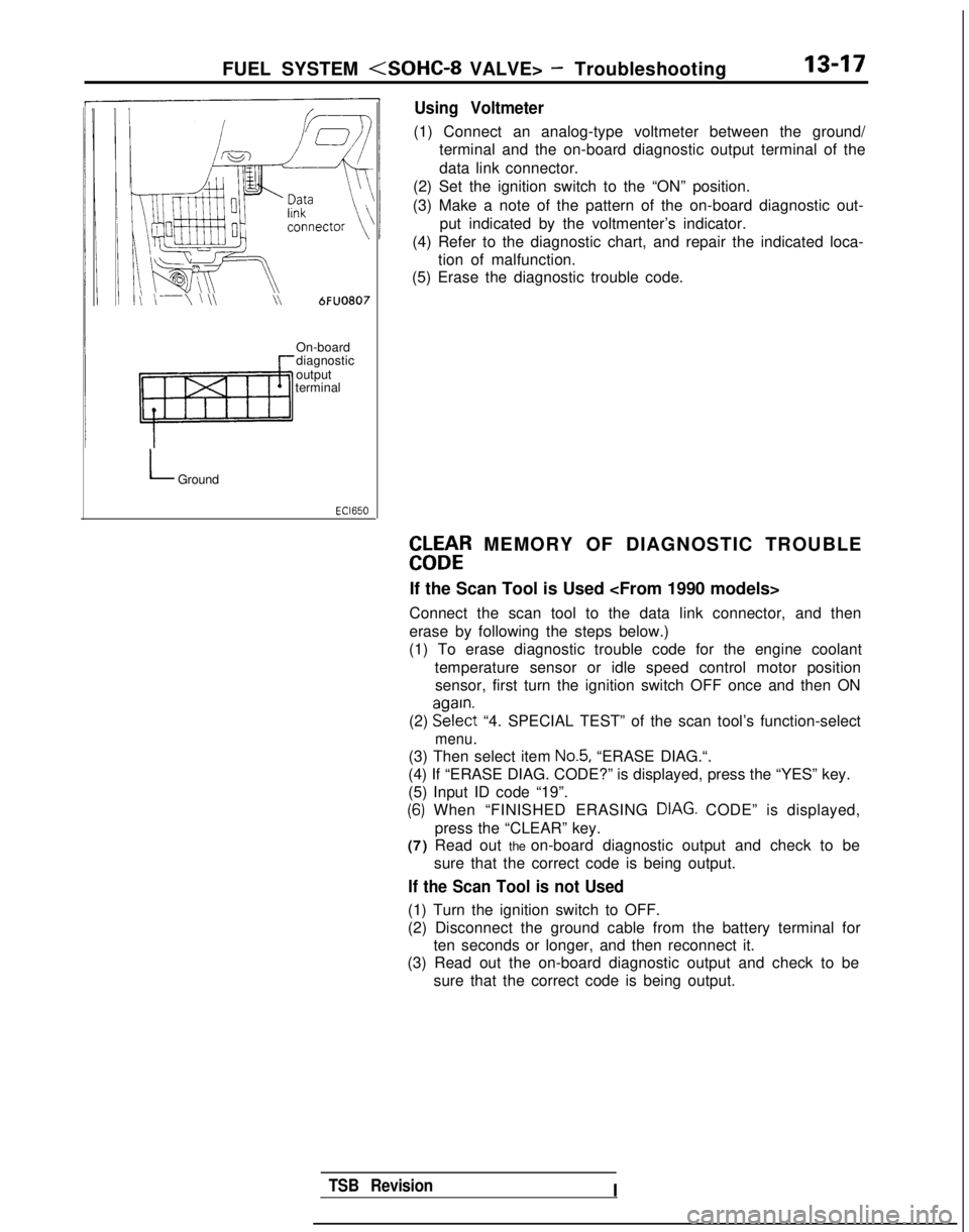
Using Voltmeter
(1) Connect an analog-type voltmeter between the ground/
terminal and the on-board diagnostic output terminal of the
data link connector.
(2) Set the ignition switch to the “ON” position.
(3) Make a note of the pattern of the on-board diagnostic out- put indicated by the voltmenter’s indicator.
(4) Refer to the diagnostic chart, and repair the indicated loca- tion of malfunction.
(5) Erase the diagnostic trouble code.
On-board
diagnostic
output
terminal
LGround
EbLbtR MEMORY OF DIAGNOSTIC TROUBLE
If the Scan Tool is Used
Connect the scan tool to the data link connector, and then
erase by following the steps below.)
(1) To erase diagnostic trouble code for the engine coolant
temperature sensor or idle speed control motor positionsensor, first turn the ignition switch OFF once and then ON
(2) EE?$t
“4. SPECIAL TEST” of the scan tool’s function-select
menu.
(3) Then select item No.5, “ERASE DIAG.“.
(4) If “ERASE DIAG. CODE?” is displayed, press the “YES” k\
ey.
(5) Input ID code “19”.
(6) When “FINISHED ERASING DIAG. CODE” is displayed,> Ipress the “CLEAR” key.
(7) Read out the on-board diagnostic output and check to be
sure that the correct code is being output.
If the Scan Tool is not Used
(1) Turn the ignition switch to OFF.
(2) Disconnect the ground cable from the battery terminal forten seconds or longer, and then reconnect it.
(3) Read out the on-board diagnostic output and check to be
sure that the correct code is being output.
TSB RevisionI
Page 160 of 1273
13-18
FUEL SYSTEM
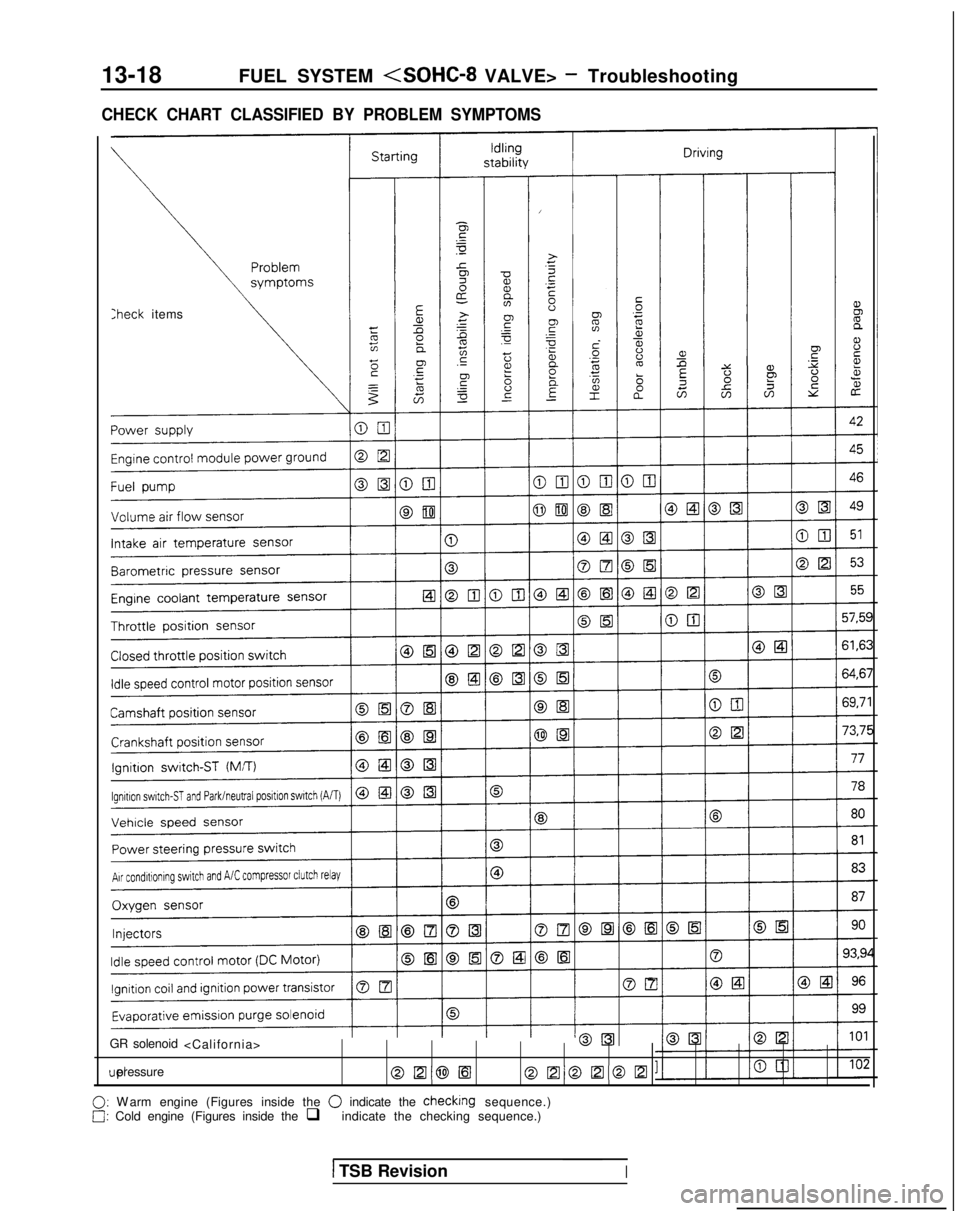
CHECK CHART CLASSIFIED BY PROBLEM SYMPTOMS
:heck items
GR solenoid
@El@lEloEloElom
0: W
arm engine (Figures inside the
0 indicate the checking sequence.)0: Cold engine (Figures inside the
q indicate the checking sequence.)
1 TSB RevisionI