MITSUBISHI GALANT 1989 Service Repair Manual
Manufacturer: MITSUBISHI, Model Year: 1989, Model line: GALANT, Model: MITSUBISHI GALANT 1989Pages: 1273, PDF Size: 37.62 MB
Page 121 of 1273
ENGINE
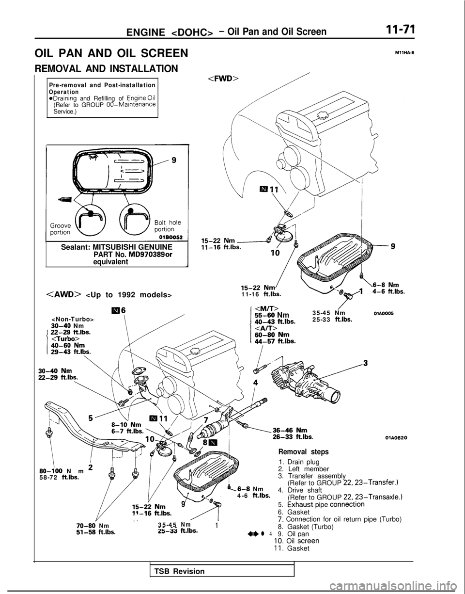
OIL PAN AND OIL SCREEN
REMOVAL AND INSTALLATION
Pre-removal and Post-installationOperation*Draining and Refilling of
Engine
011(Refer to GROUP OO-MamtenanceService.)
Sealant: MITSUBISHI GENUINE
PART No. MD970389or
equivalent
30-40 Nm1 22-28 Fibs.I
/
11-16 ft.lbs.
I
55-60 Nm
35-45 NmOlA0005
do-43 ft.lbs.25-33 ft.lbs.
Removal steps
1. Drain plug
2. Left member
3. Transfer assembly (Refer to GROUP
22,23-Transfer.)6-8 Nm
4-6 ft.lbs.4. Drive shaft
(Refer to GROUP 22.23-Transaxle.)
OlA0620
SO-:00 Nm *58-72 ft.lbs. 70-80’
Nm
51-58
ft.lbs.
/ - -e
95.ixhaust pipe connedtion
, .A6.Gasket
Nm17. Connection for oil return pipe (Turbo)
25-33ft.lbs.8.Gasket (Turbo)4*l 49.Oil pan
35-45
-- -
-
10. Oil
screen11. Gasket
TSB Revision
Page 122 of 1273
11-72
ENGINE
1
OlR0606
Sealant
Groove 4 m
m
(.I 6
in.)
p4L
cut off
-01 BOOS1e
SERVICE POINTS OF REMOVALMllHBAFl
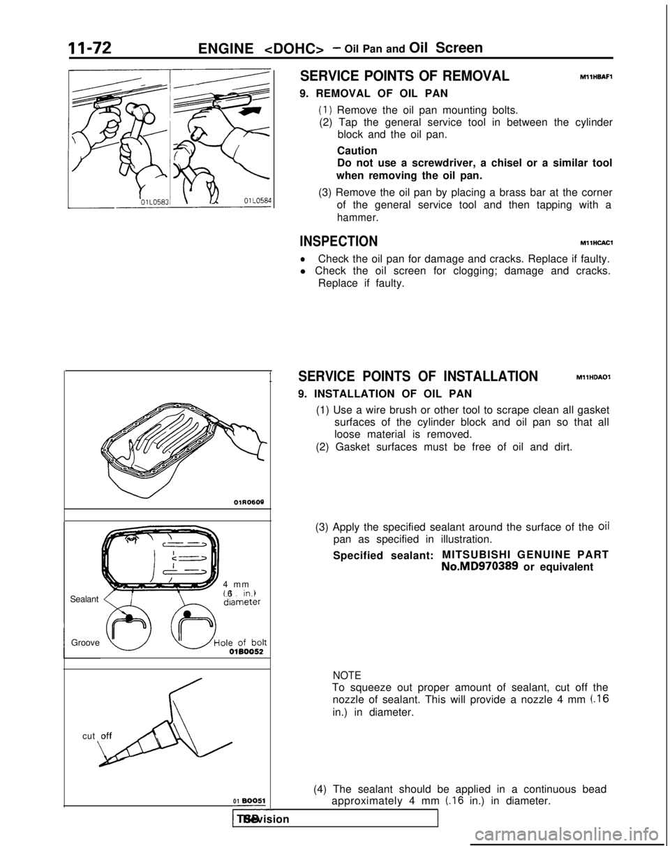
9. REMOVAL OF OIL PAN
(1) Remove the oil pan mounting bolts.
(2) Tap the general service tool in between the cylinder block and the oil pan.
Caution
Do not use a screwdriver, a chisel or a similar tool
when removing the oil pan.
(3) Remove the oil pan by placing a brass bar at the corner of the general service tool and then tapping with a
hammer.
INSPECTIONMllHCACl
lCheck the oil pan for damage and cracks. Replace if faulty.
l Check the oil screen for clogging; damage and cracks.
Replace if faulty.
SERVICE POINTS OF INSTALLATIONMllHDAOl
9. INSTALLATION OF OIL PAN
(1) Use a wire brush or other tool to scrape clean all gasket surfaces of the cylinder block and oil pan so that all
loose material is removed.
(2) Gasket surfaces must be free of oil and dirt.
(3) Apply the specified sealant around the surface of the
oil
pan as specified in illustration.
Specified sealant: MITSUBISHI GENUINE PART
No.MD970389 or equivalent
NOTE
To squeeze out proper amount of sealant, cut off the
nozzle of sealant. This will provide a nozzle 4 mm
(.I6
in.) in diameter.
(4) The sealant should be applied in a continuous bead approximately 4 mm
(.I6 in.) in diameter.
1 TSB Revision
Page 123 of 1273
ENGINE
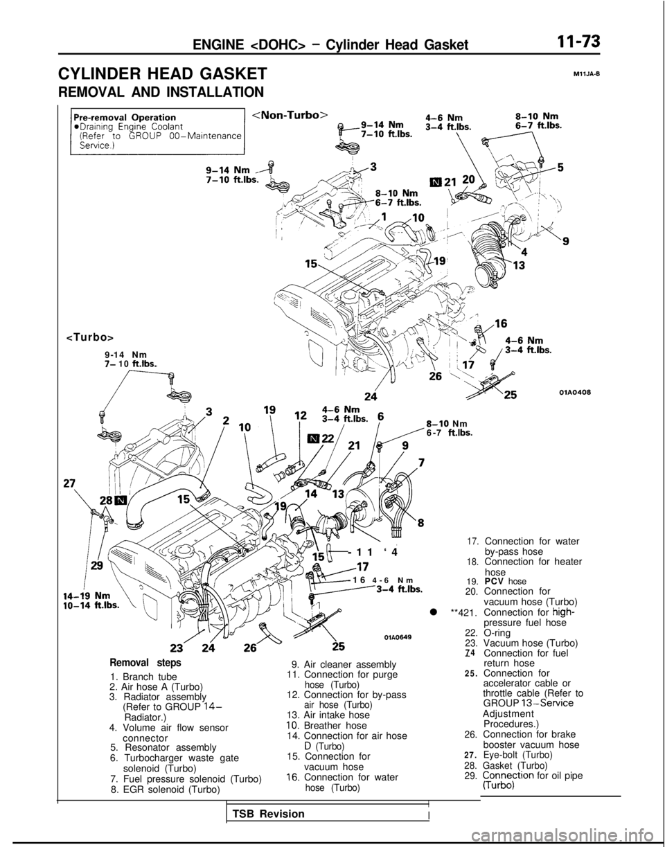
CYLINDER HEAD GASKET
MllJA-9
REMOVAL AND INSTALLATION
7- 10 ft.lbs.
OlA0408
8-10 Nm
6-7 ft.lbs.
-11 ‘
4
A17
-16
4-6 N
m
---3-4
ftlbs.
OlA0649
17.
18.
19.20.
l **421.
22.
23.
74Removal steps
1. Branch tube
2. Air hose A (Turbo)
3. Radiator assembly (Refer to GROUP
14-Radiator.)
4. Volume air flow sensor
connector
5. Resonator assembly
6. Turbocharger waste gate solenoid (Turbo)
7. Fuel pressure solenoid (Turbo) 8. EGR solenoid (Turbo)
-
9. Air cleaner assembly
11. Connection for purge25.
hose (Turbo)12. Connection for by-passair hose (Turbo)13. Air intake hose10. Breather hose
14. Connection for air hose26.
D (Turbo)15. Connection for27.
vacuum hose28.
16. Connection for water29.
hose (Turbo)
I
Connection for water
by-pass hose
Connection for heater
hose
PCV hose
Connection for
vacuum hose (Turbo)
Connection for
high-pressure fuel hose
O-ring
Vacuum hose (Turbo) Connection for fuel
return hose
Connection for
accelerator cable or
throttle cable (Refer to GROUP
13-ServiceAdjustment
Procedures.)
Connection for brake
booster vacuum hose
Eye-bolt (Turbo)
Gasket (Turbo)
pun;;;tron for oil pipe
TSB Revision
I
Page 124 of 1273
11-74ENGINE
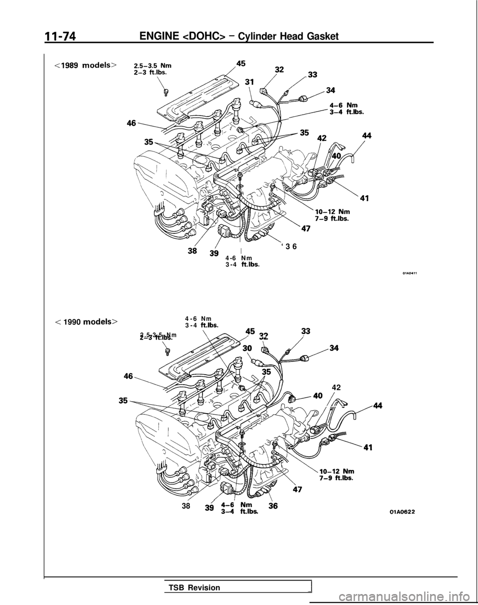
< 1990 models>
/
d34
/./At %L.
I4-6 Nm
3-4 ftlbs.
‘36
4-6
Nm3-
4 ftlbs.
2.5-3.5Nm\45
13 33
42
/A
3839/ z-i ,“g,- . .OlA0622
TSB Revision
Page 125 of 1273
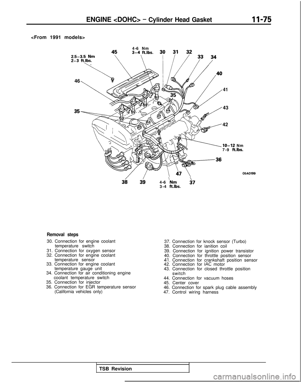
ENGINE
Z&-y,bfm
‘\ .
,,\:.,.s.
46
4-6
‘Nm $7
3-4 ftlbs.
41
43
42
IO-12 Nm
7-9 ft.lbs.
05A0199
Removal steps
30. Connection for engine coolant
temperature switch
31. Connection for oxygen sensor
32. Connection for engine coolant temperature sensor
33. Connection for engine coolant
temperature gauge unit
34. Connection for air conditioning engine
coolant temperature switch
35. Connection for injector
36. Connection for EGR temperature sensor
(California vehicles only) 37. Connection for knock sensor (Turbo)
38. Connection for ianition coil
39. Connection for ignition power transistor
40. Connection for throttle position sensor
41. Connection for crankshaft position sensor
42. Connection for IAC motor
43. Connection for closed throttle position
switch
44. Connection for vacuum hoses
45. Center cover
46. Connection for spark plug cable assembly
47. Control wiring harness
TSB Revision
Page 126 of 1273
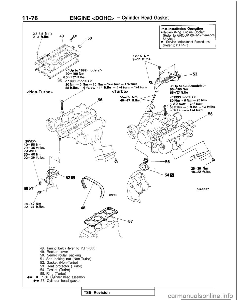
11-76
ENGINE
2.5-3.5
N
m
2-3 ft.lbs.
49
l’/
50
_ 65-72 ftlbs.
e
- 14 ft.lbs. -4 turn +I/4 turna ,a _..--/I In +n lQQ3 mnrimls>- II ~
i/4wrn + 114xurnrAVJ
.vp .” .““L . ..-..-.I-^^ -^^I.~1-_ _- .-..-YU-IUU NIT5.
<199” ---I-‘-’80 Nn, - v ,.lll - Lw .-...II I” I.._^
66-77 ft Ih!
* IA +.*r..
*Replenishing
Engine Coolant
(Refer to GROUP OO-Maintenance
l Service ‘Adjustment Procedures(Refer to P.l l-57.)I
12-15 Nm
9-11
ft.lbs.
/
:WD>40-50 NmW3i,ft.lbs...,....I,30-40 NmI
3_2- 29 ftlbs.b. I\
\$ 1
‘\I
L. I
Q51 ,-,?/*
r
r
30-46 Nm22-29 ft.lbs. I.5
rrl”“els~n .nNm-7nNm
48. Timing belt (Refer to P.l I-80.)49. Rocker cover
50. Semi-circular packing
51. Self locking nut (Non-Turbo)
52. Gasket (Non-Turbo)
53. Heat protector (Turbo)
54. Gasket (Turbo)55. Ring (Turbo)+, l * 56. Cylinder head assembly~~ 57. Cylinder head gasket
+ I,4 L”,,, - #l-t L”lllj8 ft.lbs. - 0 ft.lbs. - 14 ft.lbs.,J -1 IA turn + 1 IO turn
25-30 him
18-22
ft.lbs.‘54m
OlA0567
TSB Revision
Page 127 of 1273
![MITSUBISHI GALANT 1989 Service Repair Manual ENGINE <DOHC>- Cylinder Head GasketII-77
SFAI ING
POINTSGaln
OlA0155
J
Front of engine I)Intake side
]
Exhaust side
SERVICE POINTS OF REMOVALMllJBAUa
21. DISCONNECTION OF HIGH-PRESSURE FUEL HOSE
Cauti MITSUBISHI GALANT 1989 Service Repair Manual ENGINE <DOHC>- Cylinder Head GasketII-77
SFAI ING
POINTSGaln
OlA0155
J
Front of engine I)Intake side
]
Exhaust side
SERVICE POINTS OF REMOVALMllJBAUa
21. DISCONNECTION OF HIGH-PRESSURE FUEL HOSE
Cauti](/img/19/57312/w960_57312-126.png)
ENGINE
SFAI ING
POINTSGaln
OlA0155
J
Front of engine I)Intake side
]
Exhaust side
SERVICE POINTS OF REMOVALMllJBAUa
21. DISCONNECTION OF HIGH-PRESSURE FUEL HOSE
Caution
Cover the hose connection with rags to prevent splash
of fuel that could be caused by some residual pressure
in the fuel pipe line.
For information concerning the bleeding of the residualpressure, refer to GROUP
13-On-vehicle Inspection of MFI Components.
56. REMOVAL OF CYLINDER HEAD ASSEMBLY Using the tool, loosen the bolts in the order shown in the
figure (in 2 or 3 cycles) and remove. Then remove the cylin-
der head assembly.
TSB Revision
I
Page 128 of 1273
ENGINE
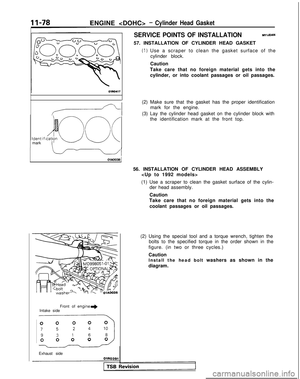
SERVICE POINTS OF INSTALLATIONMllJDAN
57. INSTALLATION OF CYLINDER HEAD GASKET
(1) Use a scraper to clean the gasket surface of the
cylinder block.
Ident i f ido c\ (Imark\ OlAOO38
Front of
engine+Intake side
.miJ
Exhaust side Caution
Take care that no foreign material gets into the cylinder, or into coolant passages or oil passages.
(2) Make sure that the gasket has the proper identification mark for the engine.
(3) Lay the cylinder head gasket on the cylinder block with the identification mark at the front top.
56. INSTALLATION OF CYLINDER HEAD ASSEMBLY
(1) Use a scraper to clean the gasket surface of the cylin- der head assembly.
Caution
Take care that no foreign material gets into the
coolant passages or oil passages.
(2) Using the special tool and a torque wrench, tighten the bolts to the specified torque in the order shown in the
figure. (in two or three cycles.)
Caution
Install the head bolt washers as shown in the
diagram.
Page 129 of 1273
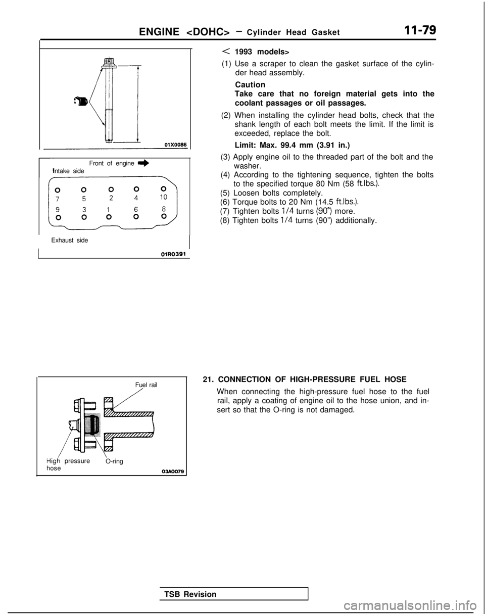
ENGINE
Front of engine I)Intake side
Exhaust side
OlR0391
Fuel rail/
Hig; pressure \
O-ring
hose
03Aoo79
< 1993 models>
(1) Use a scraper to clean the gasket surface of the cylin- der head assembly.
Caution
Take care that no foreign material gets into the
coolant passages or oil passages.
(2) When installing the cylinder head bolts, check that the shank length of each bolt meets the limit. If the limit is
exceeded, replace the bolt.
Limit: Max. 99.4 mm (3.91 in.)
(3) Apply engine oil to the threaded part of the bolt and the washer.
(4) According to the tightening sequence, tighten the bolts
to the specified torque 80 Nm (58 ftlbs.).
(5) Loosen bolts completely.
(6) Torque bolts to 20 Nm (14.5 ftlbs.).
(7) Tighten bolts
l/4 turns (90”) more.
(8) Tighten bolts
l/4 turns (90”) additionally.
TSB Revision 21. CONNECTION OF HIGH-PRESSURE FUEL HOSE
When connecting the high-pressure fuel hose to the fuelrail, apply a coating of engine oil to the hose union, and in-
sert so that the O-ring is not damaged.
Page 130 of 1273
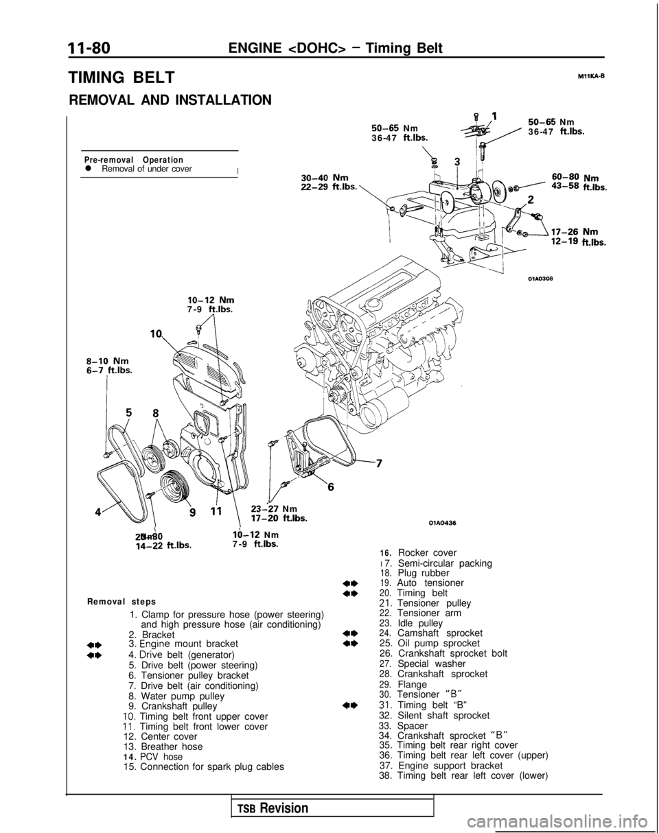
II-80ENGINE
TIMING BELT
REMOVAL AND INSTALLATION 50-65
Nm
36-47 ftlbs.
A7Pre-removal Operationl Removal of under coverI MIlKA-B
50-65
Nm
36-47
ft.lbs.
ii!&.
lo-12 Nm7-9 ft.lbs.
8-10 Nm
23--27 Nm 17-20
ft.lbs. 20-A0 Nm
lb-12 Nm
14-22
ftlbs.
7-9 ft.lbs.
Removal steps
1. Clamp for pressure hose (power steering)
and high pressure hose (air conditioning)
2. Bracket
3.
Enoine mount bracket
ii4. D&e belt (generator)
5. Drive belt (power steering)
6. Tensioner pulley bracket
7. Drive belt (air conditioning)
8. Water pump pulley
9. Crankshaft pulley
10. Timing belt front upper coverII. Timing belt front lower cover
12. Center cover
13. Breather hose
14. PCV hose15. Connection for spark plug cables
ft.lbs.
4*a*
4**I)
4* OlAO436
16.Rocker cover
I 7. Semi-circular packing
18.Plug rubber19.Auto tensioner20.Timing belt21.Tensioner pulley22.Tensioner arm23.Idle pulley24.Camshaft sprocket
25. Oil pump sprocket
26. Crankshaft sprocket bolt
27.Special washer28.Crankshaft sprocket29.Flange30.Tensioner “B”31. Timing belt “B”
32. Silent shaft sprocket
33.Spacer
34. Crankshaft sprocket “B”35. Timing belt rear right cover
36. Timing belt rear left cover (upper)
37. Engine support bracket
38. Timing belt rear left cover (lower)
TSB Revision