MITSUBISHI GALANT 1989 Service Repair Manual
Manufacturer: MITSUBISHI, Model Year: 1989, Model line: GALANT, Model: MITSUBISHI GALANT 1989Pages: 1273, PDF Size: 37.62 MB
Page 471 of 1273
ENGINE CONTROL - Service Adjustment Procedures13-329
SERVICE ADJUSTMENT PROCEDW,E,t&
ACCELERATOR CABLE INSPECTION AND
ADJUSTMENT
For models equipped with the auto-cruise control system, refer
to P. 13-398.
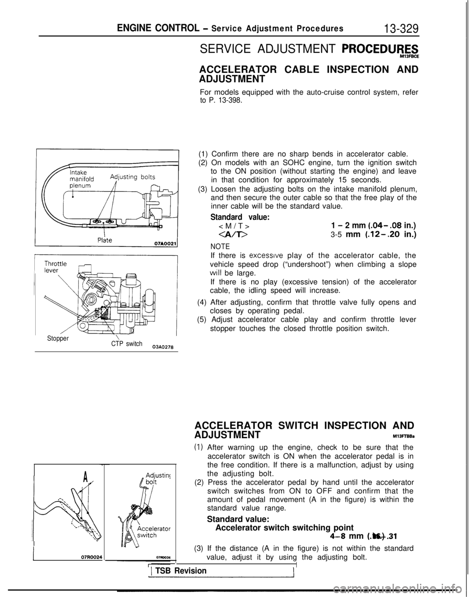
(1) Confirm there are no sharp bends in accelerator cable.
(2) On models with an SOHC engine, turn the ignition switch to the ON position (without starting the engine) and leave
in that condition for approximately 15 seconds.
(3) Loosen the adjusting bolts on the intake manifold plenum, and then secure the outer cable so that the free play of theinner cable will be the standard value.
Standard value:
1 - 2 mm (.04- .08
in.)
-a/T>3-5 mm (.12-.20 in.)
NOTE
If there is excessrve play of the accelerator cable, the
vehicle speed drop (“undershoot”) when climbing a slope will
be large.
If there is no play (excessive tension) of the accelerator
cable, the idling speed will increase.
(4) After adjusting, confirm that throttle valve fully opens and closes by operating pedal.
(5) Adjust accelerator cable play and confirm throttle lever
stopper touches the closed throttle position switch.
Stopper\CTP switch03AO278
A
.-\\‘\.\ ‘\
!4
:l/.\\ \\‘\ I\*\\”
j 07R0024
ACCELERATOR SWITCH INSPECTION AND
ADJUSTMENTM13FTBBa
(1) After warning up the engine, check to be sure that theaccelerator switch is ON when the accelerator pedal is in
the free condition. If there is a malfunction, adjust by using
the adjusting bolt.
(2) Press the accelerator pedal by hand until the accelerator switch switches from ON to OFF and confirm that the
amount of pedal movement (A in the figure) is within the
standard value range.
Standard value: Accelerator switch switching point
4-8 mm (.16-.31 in.)
(3) If the distance (A in the figure) is not within the standard value, adjust it by using the adjusting bolt.
I1 TSB Revision
Page 472 of 1273
13-330ENGINE CONTROL - Engine Control
ENGINE CONTROL
REMOVAL AND INSTALLATIONM13OA--
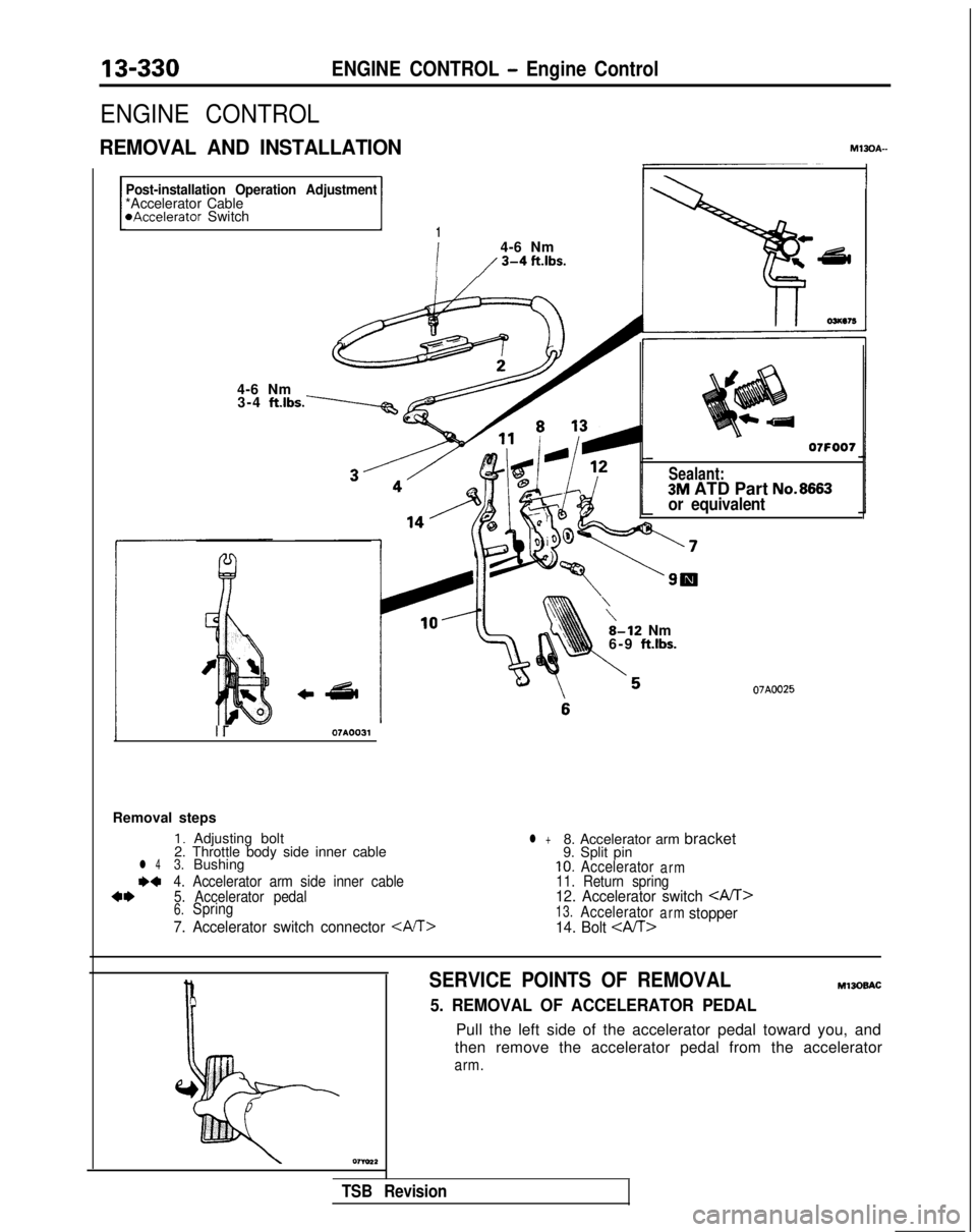
Post-installation Operation Adjustment*Accelerator Cable*Accelerator SwitchI1
i
4-6 Nm
/ 3-4 ft-‘bs.
4-6 Nm3-4 ft.lbs.\
Sealant:3M ATD Part No.8663or equivalent
\8-12 Nm
6-9 ft.lbs.
07A0025
lr07A0031
Removal steps
1. Adjusting bolt
2. Throttle body side inner cable
l 43.Bushing
I)+4. Accelerator arm side inner cable4*5. Accelerator pedal6.Spring
7. Accelerator switch connector CM>
l +8. Accelerator arm bracket
9. Split pin
10.Acceleratorarm11. Return spring12. Accelerator switch CM>13.Acceleratorarmstopper
14. Bolt
SERVICE POINTS OF REMOVALM13oBAC
5. REMOVAL OF ACCELERATOR PEDAL
Pull the left side of the accelerator pedal toward you, and
then remove the accelerator pedal from the accelerator
arm.
TSB Revision
Page 473 of 1273
ENGINE CONTROL - Engine Control13-331
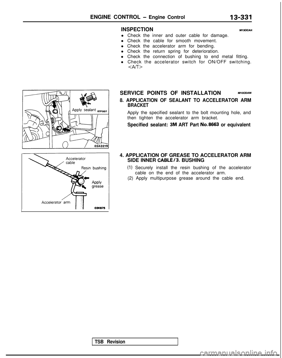
4. APPLICATION OF GREASE TO ACCELERATOR ARM
SIDE INNER
CABLE/3. BUSHING
(1) Securely install the resin bushing of the accelerator
cable on the end of the accelerator arm.
(2) Apply multipurpose grease around the cable end.
INSPECTIONMl3ocAH
l Check the inner and outer cable for damage.
l Check the cable for smooth movement.
l Check the accelerator arm for bending.
l Check the return spring for deterioration.
l Check the connection of bushing to end metal fitting.
l Check the accelerator switch for ON/OFF switching.
SERVICE POINTS OF INSTALLATIONMlJODAW
8. APPLICATION OF SEALANT TO ACCELERATOR ARM
BRACKET
Apply the specified sealant to the bolt mounting hole, and
then tighten the accelerator arm bracket.
Specified sealant: 3M ART Part No.8663 or equivalent
TSB Revision
Page 474 of 1273
13-332
AUTO-CRUISE CONTROL SYSTEM - Specifications
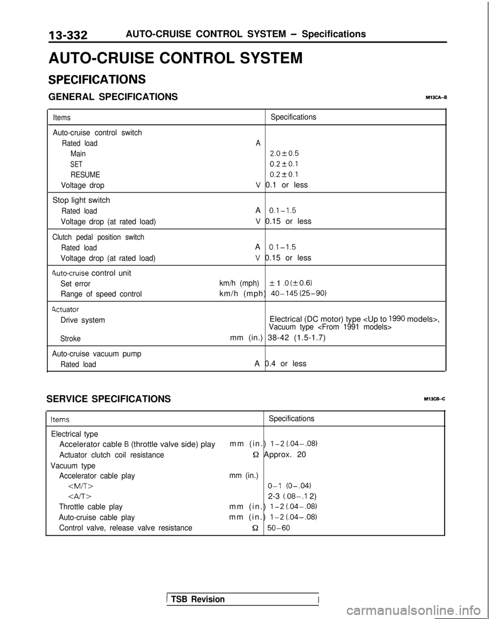
AUTO-CRUISE CONTROL SYSTEM
SPECIFICATIONS
GENERAL SPECIFICATIONSM13CA--B
Items
Auto-cruise control switch
Rated load Main
SET
RESUME
Voltage drop
Stop light switch
Rated load
Voltage drop (at rated load)
Clutch pedal position switch
Rated load
Voltage drop (at rated load)
4uto-cruise control unit
Set errorRange of speed control
4ctuator
Drive system
Stroke
Auto-cruise vacuum pump
Rated load
Specifications
A
2.0f0.5
0.2fO.l 0.2t-0.1
V 0.1 or less
A
0.1-1.5
V 0.15 or less
A
0.1-1.5
V 0.15 or less
km/h (mph)IL 1 .O (kO.6)
km/h (mph) 40-145
(25-90)
Electrical (DC motor) type
mm (in.) 38-42 (1.5-1.7)
A 0.4 or less
SERVICE SPECIFICATIONS
Ml3CB-.C
ItemsSpecifications
Electrical type
Accelerator cable B (throttle valve side) play mm (in.) l-2 (.04-.08)
Actuator clutch coil resistanceQ Approx. 20
Vacuum type
Accelerator cable play mm (in.)
Gv-r~2-3 (.08-.I 2)
Throttle cable playmm (in.) l-2 (.04-.08)
Auto-cruise cable playmm (in.) l-2
(.04-.08)
Control valve, release valve resistance52 50-60
1 TSB RevisionI
Page 475 of 1273
AUTO-CRUISE CONTROL SYSTEM - Specifications/Special Tools 13-333
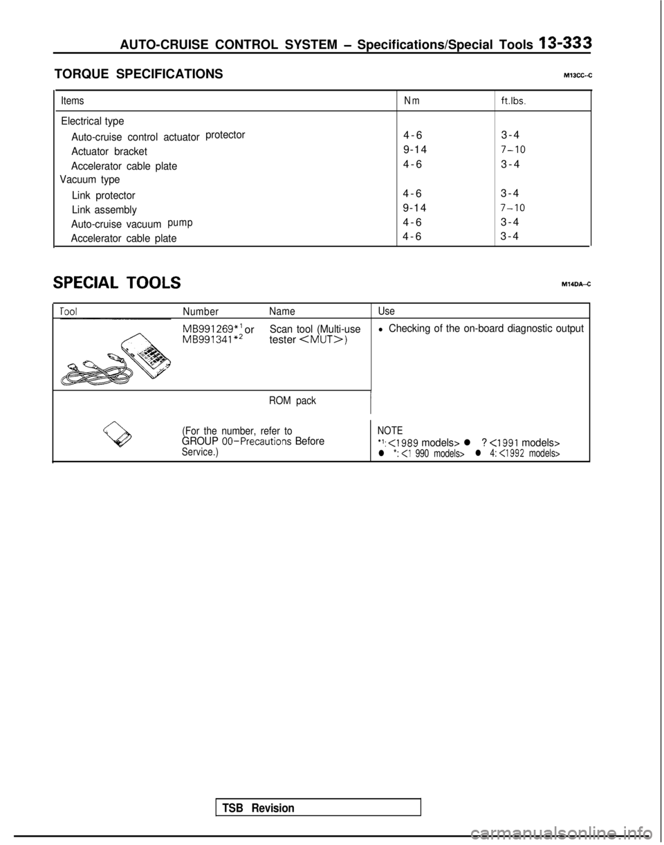
TORQUE SPECIFICATIONSMlOCC-.C
ItemsNmftlbs.
Electrical type
Auto-cruise control actuator protector
4-
6
3-4
Actuator bracket9-147-10
Accelerator cable plate4-
6
3-4
Vacuum type
Link protector
4-
6
3-4
Link assembly9-147-10
Auto-cruise vacuumpump4-
6
3-4
Accelerator cable plate4-
6
3-4
SPECIAL TOOLSM14DA-C
Number Name Use
MB991 269*’
orMB991341 **Scan tool (Multi-usel Checking of the on-board diagnostic output
tester
ROM pack
(For the number, refer to
NOTEGROUP 00-Precautions BeforeService.)‘1: <1989 models> l ? <1991 models>l *: l 4: <1992
models>
TSB Revision
Page 476 of 1273
13-334AUTO-CRUISE CONTROL SYSTEM - Troubleshooting
TROUBLESHOOTIN
G
MlJEBDH
The auto-cruise control system performs control functions for
the setting or cancellation of the fixed-speed driving speed bas-
ed upon the data provided by input signals. As a result, when
the auto-cruise control system is canceled, the cause of the
cancellation is memorized in a separate circuit by the ECU,
regardless of whether or not the auto-cruise control system
condition is normal or abnormal, thus providing the ECU with
the on-board diagnostic function by certain fixed patterns, as
well as the function of being able to check whether or not the
ECU’s input switches or sensor are normal. Thus, by effectively
using these function, the time required checking and repair can
be shortened.
NOTE
When the computer (ECU) power supply (ignition switch andmain switch) is switched OF-F, the memorized diagnostic
trouble codes are erased, and so for this reason the power
supply must be left ON until the checking is completed.
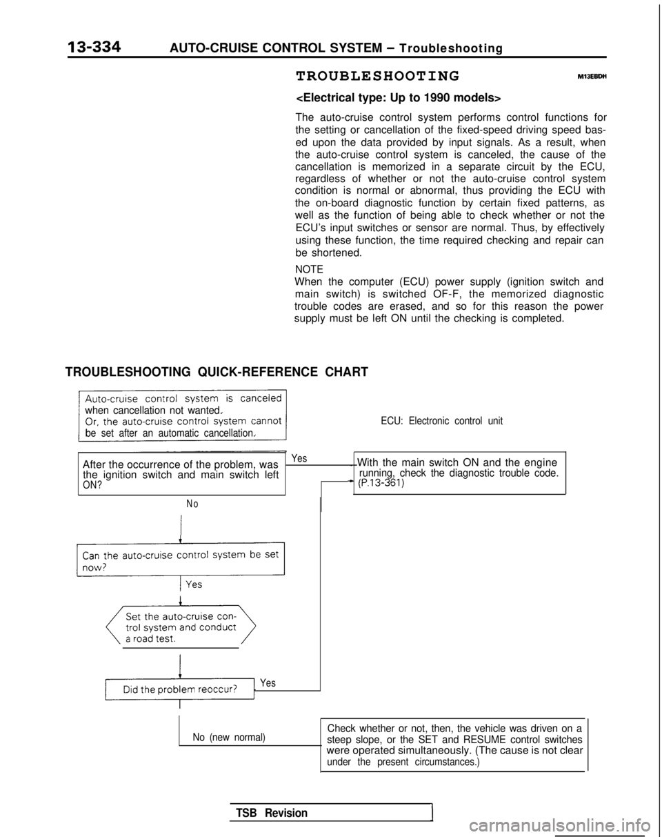
TROUBLESHOOTING QUICK-REFERENCE CHART
when cancellation not wanted.
be set after an automatic cancellation. ECU: Electronic control unit
After the occurrence of the problem, wasYes. With the main switch ON and the engine
the ignition switch and main switch leftrunning, check the diagnostic trouble code.
ON?+ (P.13-361)
No
Can the auto-cruise control system be set
_r-l;
Yes
No (new normal)Check whether or not, then, the vehicle was driven on a
steep slope, or the SET and RESUME control switches
were operated simultaneously. (The cause is not clear
under the present circumstances.)
TSB RevisionI
Page 477 of 1273
AUTO-CRUISE CONTROL SYSTEM - Troubleshooting
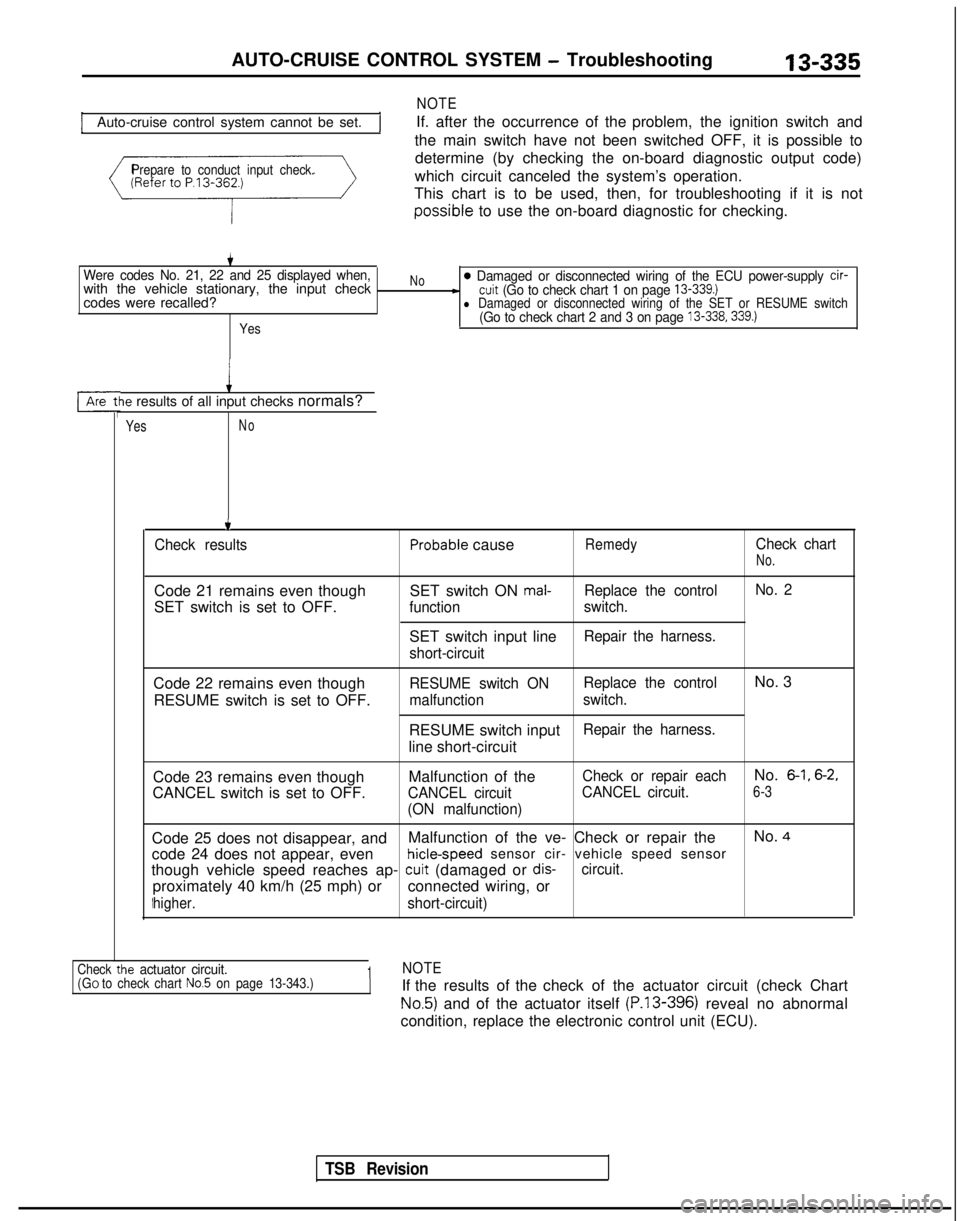
Auto-cruise control system cannot be set.
NOTE
If. after the occurrence of the problem, the ignition switch and
the main switch have not been switched OFF, it is possible to
Prepare to conduct input check.determine (by checking the on-board diagnostic output code)
which circuit canceled the system’s operation.
This chart is to be used, then, for troubleshooting if it is not possible
to use the on-board diagnostic for checking.
Were codes No. 21, 22 and 25 displayed when,with the vehicle stationary, the input check
codes were recalled?
Yes
No0 Damaged or disconnected wiring of the ECU power-supply cir--cuit (Go to check chart 1 on page 13-339.)l Damaged or disconnected wiring of the SET or RESUME switch(Go to check chart 2 and 3 on page 13-338.339.)
le results of all input checks normals?
YesNo
.t
TSB Revision
.
Check resultsProbable causeRemedyCheck chart
No.
Code 21 remains even though
SET switch is set to OFF. SET switch ON mal-Replace the control
No. 2
function switch.
SET switch input lineRepair the harness.
short-circuit
Code 22 remains even though RESUME switch is set to OFF.RESUME switch ON Replace the controlNo. 3
malfunction
switch.
RESUME switch inputRepair the harness.
line short-circuit
Code 23 remains even though
CANCEL switch is set to OFF. Malfunction of the
CANCEL circuit
(ON malfunction) Check or repair each
No. 6-1, 6-2,
CANCEL circuit.6-3
Code 25 does not disappear, and
Malfunction of the ve- Check or repair the No. 4
code 24 does not appear, even hicle-speed
sensor cir- vehicle speed sensor
though vehicle speed reaches ap-
cuit (damaged or dis-circuit.
proximately 40 km/h (25 mph) or connected wiring, or
higher.short-circuit)
ie actuator circuit.1NOTECheck tl(GO to check chart No.5 on page 13-343.)If the results of the check of the actuator circuit (check Chart
No.5) and of the actuator itself (P.13-396) reveal no abnormal
condition, replace the electronic control unit (ECU).
Page 478 of 1273
13-336AUTO-CRUISE CONTROL SYSTEM - Troubleshooting
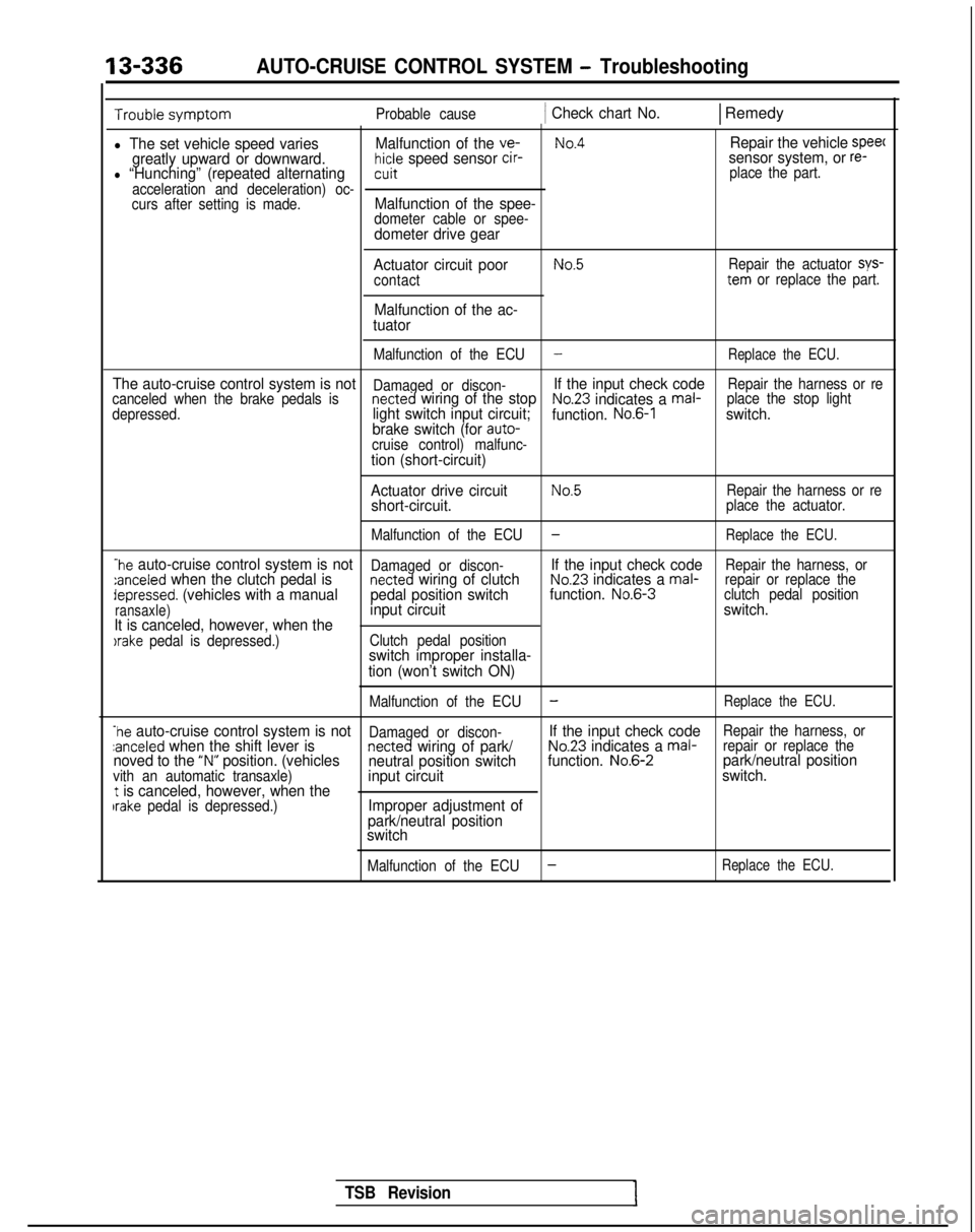
Probable cause1 Check chart No.1 Remedy
l The set vehicle speed variesMalfunction of the ve-No.4Repair the vehicle speec
greatly upward or downward.hicle speed sensor cir-sensor system, or re-l “Hunching” (repeated alternatingcuit place the part.
acceleration and deceleration) oc-
curs after setting is made.
Malfunction of the spee-dometer cable or spee-dometer drive gear
Actuator circuit poor
contact
Malfunction of the ac-
tuator
No.5Repair the actuator sys-tern or replace the part.
Malfunction of the ECU
-Replace the ECU.
The auto-cruise control system is notDamaged or discon-If the input check codeRepair the harness or re
canceled when the brake pedals isnetted wiring of the stopNo.23 indicates a mal- place the stop light
depressed.light switch input circuit; function. No.6-1switch.
brake switch (for auto-
cruise control) malfunc-
tion (short-circuit)
Actuator drive circuit
No.5Repair the harness or reshort-circuit.place the actuator.
Malfunction of the ECU
-Replace the ECU.
-he auto-cruise control system is notDamaged or discon-If the input check codeRepair the harness, or:anceled when the clutch pedal isnetted wiring of clutchNo.23 indicates a mal- repair or replace thedepressed. (vehicles with a manual pedal position switchfunction. No.6-3
clutch pedal position
ransaxle)input circuit switch.
It is canceled, however, when the
)rake pedal is depressed.) Clutch pedal positionswitch improper installa-
tion (won’t switch ON)
Malfunction of the ECU-Replace the ECU.
-he auto-cruise control system is notDamaged or discon-If the input check codeRepair the harness, orzanceled when the shift lever isnetted wiring of park/No.23 indicates a mal- repair or replace thenoved to the “N” position. (vehicles
neutral position switch function. No.6-2park/neutral positionvith an automatic transaxle)input circuit switch.t is canceled, however, when theIrake pedal is depressed.)Improper adjustment of
park/neutral position
switch
Malfunction of the ECU-Replace the ECU.
TSB Revision
Page 479 of 1273
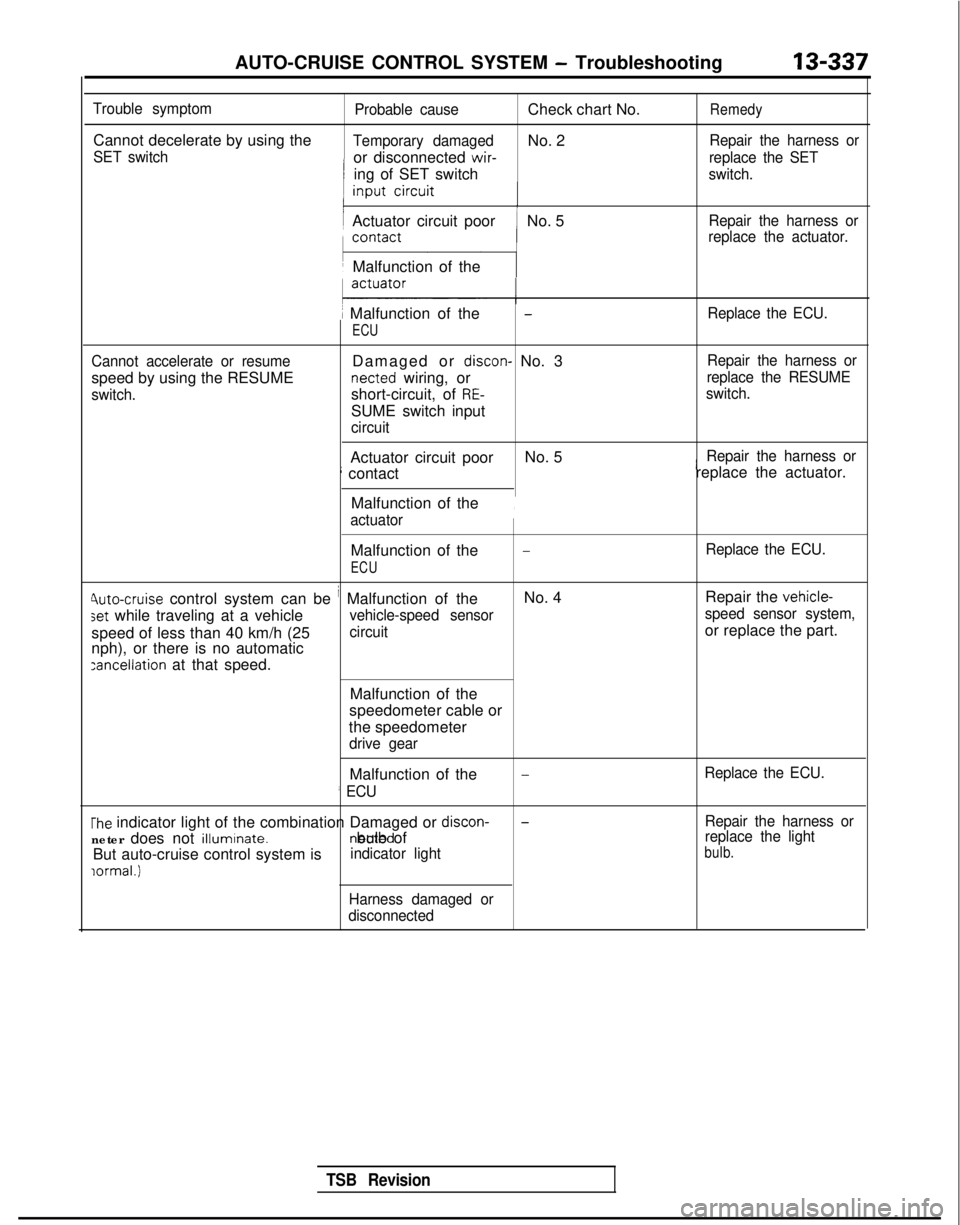
AUTO-CRUISE CONTROL SYSTEM - Troubleshooting
13-337
Trouble symptom
Cannot decelerate by using the
SET switch
Probable cause
Check chart No.Remedy
Temporary damagedNo. 2Repair the harness or
or disconnected wir-
replace the SET
ing of SET switchswitch.
Actuator circuit poorNo. 5Repair the harness or
replace the actuator.
Malfunction of the
1 Malfunction of the
ECU
-Replace the ECU.
Cannot accelerate or resume
speed by using the RESUME
switch.
Damaged or discon- No. 3 netted
wiring, or
short-circuit, of
RE-
SUME switch input
circuit Repair the harness or
replace the RESUME
switch.
Actuator circuit poor No. 5iRepair the harness or
; contact replace the actuator.
Malfunction of the
actuator
,
Malfunction of the-Replace the ECU.
ECU
Jute-cruise control system can be i Malfunction of the No. 4
Repair the vehicle-
set while traveling at a vehiclevehicle-speed sensor speed sensor system,
speed of less than 40 km/h (25circuitor replace the part.
nph), or there is no automatic
zancellation at that speed.
Malfunction of the
speedometer cable or
the speedometer
drive gear
Malfunction of the
’ ECU
-Replace the ECU.
The indicator light of the combination Damaged or discon-
neter does not illuminate. netted bulb of
But auto-cruise control system isindicator light
lormal.1
-Repair the harness or
replace the light
bulb.
Harness damaged or
disconnected
TSB Revision
Page 480 of 1273

13-338AUTO-CRUISE CONTROL SYSTEM - Troubleshooting
Trouble symptomProbable causeCheck chart No.Remedy
Malfunction of control function by
Malfunction of circuitNo. 7Repair the harness or
ON/OFF switching of ELC 4
A/Trelated to acceleratorreplace the part.
accelerator switch switch OFF function
(Non-operation of torque converterclutch, 2nd gear hold, etc.)
Malfunction of the
ECU
Overdrive is not canceled during
fixed speed driving.
Malfunction of circuitNo. 8Repair the harness or
related to overdrive
replace the part.
cancelation, or mal-
function of ECU
No shift to overdrive during man-
ual driving.
.
TSB
Revision