MITSUBISHI GALANT 1989 Service Repair Manual
Manufacturer: MITSUBISHI, Model Year: 1989, Model line: GALANT, Model: MITSUBISHI GALANT 1989Pages: 1273, PDF Size: 37.62 MB
Page 481 of 1273
AUTO-CRUISE CONTROL SYSTEM - Troubleshooting13-339
CHECK CHART
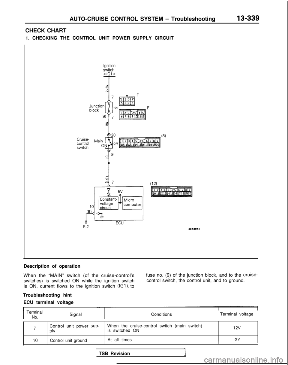
1. CHECKING THE CONTROL UNIT POWER SUPPLY CIRCUIT
Ignition
switch
(8)
Description of operation
When the “MAIN” switch (of the cruise-control’s switches) is switched ON while the ignition switch
is ON, current flows to the ignition switch (IGl),
to fuse no. (9) of the junction block, and to the cruise-
control switch, the control unit, and to ground.
Troubleshooting hint ECU terminal voltage
t
Terminal voltageI
Terminal
No.Conditions
7Control unit power sup-
When the cruise-control switch (main switch)
is switched ON 12v
PlY
10Control unit ground
At all times o
v
t
TSB Revision
Page 482 of 1273
13-340AUTO-CRUISE CONTROL SYSTEM - Troubleshooting
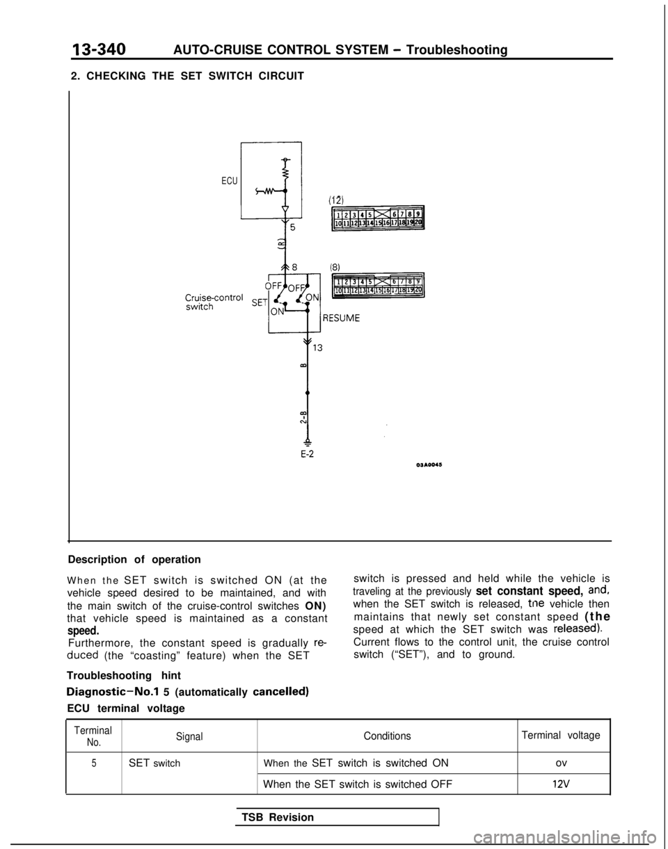
2. CHECKING THE SET SWITCH CIRCUIT
ECU
Description of operation
When the SET switch is switched ON (at the
vehicle speed desired to be maintained, and with
the main switch of the cruise-control switches ON)
that vehicle speed is maintained as a constant
speed.
Furthermore, the constant speed is gradually re- duced
(the “coasting” feature) when the SET switch is pressed and held while the vehicle is
traveling at the previously set constant speed, and,
when the SET switch is released, tne vehicle then
maintains that newly set constant speed (th
e
speed at which the SET switch was
released).
Current flows to the control unit, the cruise control switch (“SET”), and to ground.
Troubleshooting hint
Diagnostic-No.1 5 (automatically cancelled)
ECU terminal voltage
Terminal
No.SignalConditions Terminal voltage
5SET switch
When the SET switch is switched ON ov
When the SET switch is switched OFF
12v
TSB Revision
Page 483 of 1273
AUTO-CRUISE CONTROL SYSTEM - Troubleshooting13-341
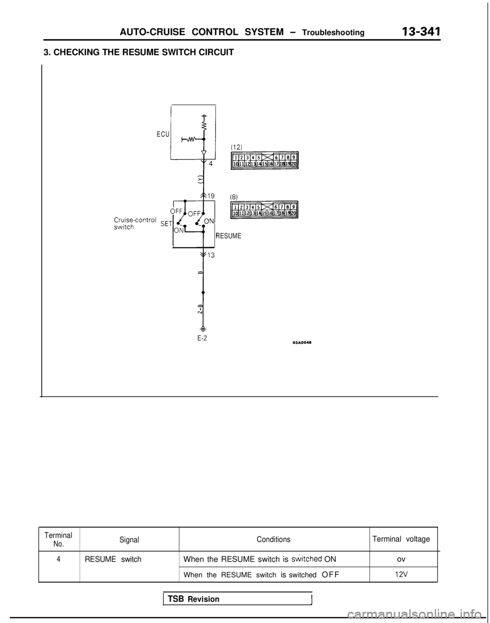
3. CHECKING THE RESUME SWITCH CIRCUIT
ECU
(12)
RESUME
E-2
Terminal
No.Signal
ConditionsTerminal voltage
4RESUME switchWhen the RESUME switch is siitched ON
ov
When the RESUME switch is switched OF
F
12v
TSB RevisionI
Page 484 of 1273
13-342AUTO-CRUISE CONTROL SYSTEM - Troubleshooting
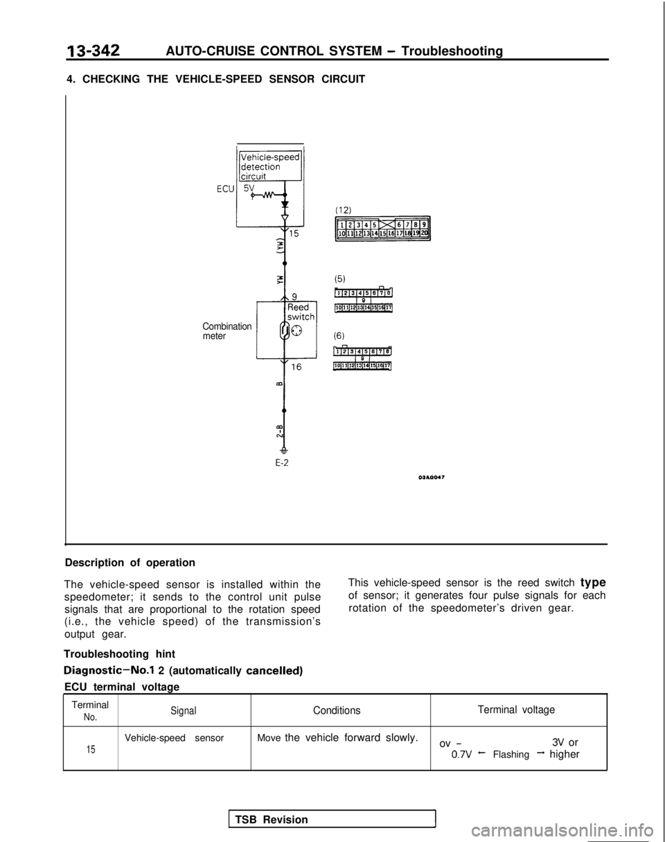
4. CHECKING THE VEHICLE-SPEED SENSOR CIRCUIT
Combination meter
E-2
Description of operation
The vehicle-speed sensor is installed within the speedometer; it sends to the control unit pulsesignals that are proportional to the rotation speed
(i.e., the vehicle speed) of the transmission’s
output gear. This vehicle-speed sensor is the reed switch type
of sensor; it generates four pulse signals for eachrotation of the speedometer’s driven gear.
Troubleshooting hint
Diagnostic-No.1 2 (automatically cancelled)
ECU terminal voltage Terminal
No.SignalConditions Terminal voltage
15
Vehicle-speed sensor
Move the vehicle forward slowly.
ov -3V or 0.7v
-Flashing-+ higher
TSB Revision
1
Page 485 of 1273
AUTO-CRUISE CONTROL SYSTEM - Troubleshooting
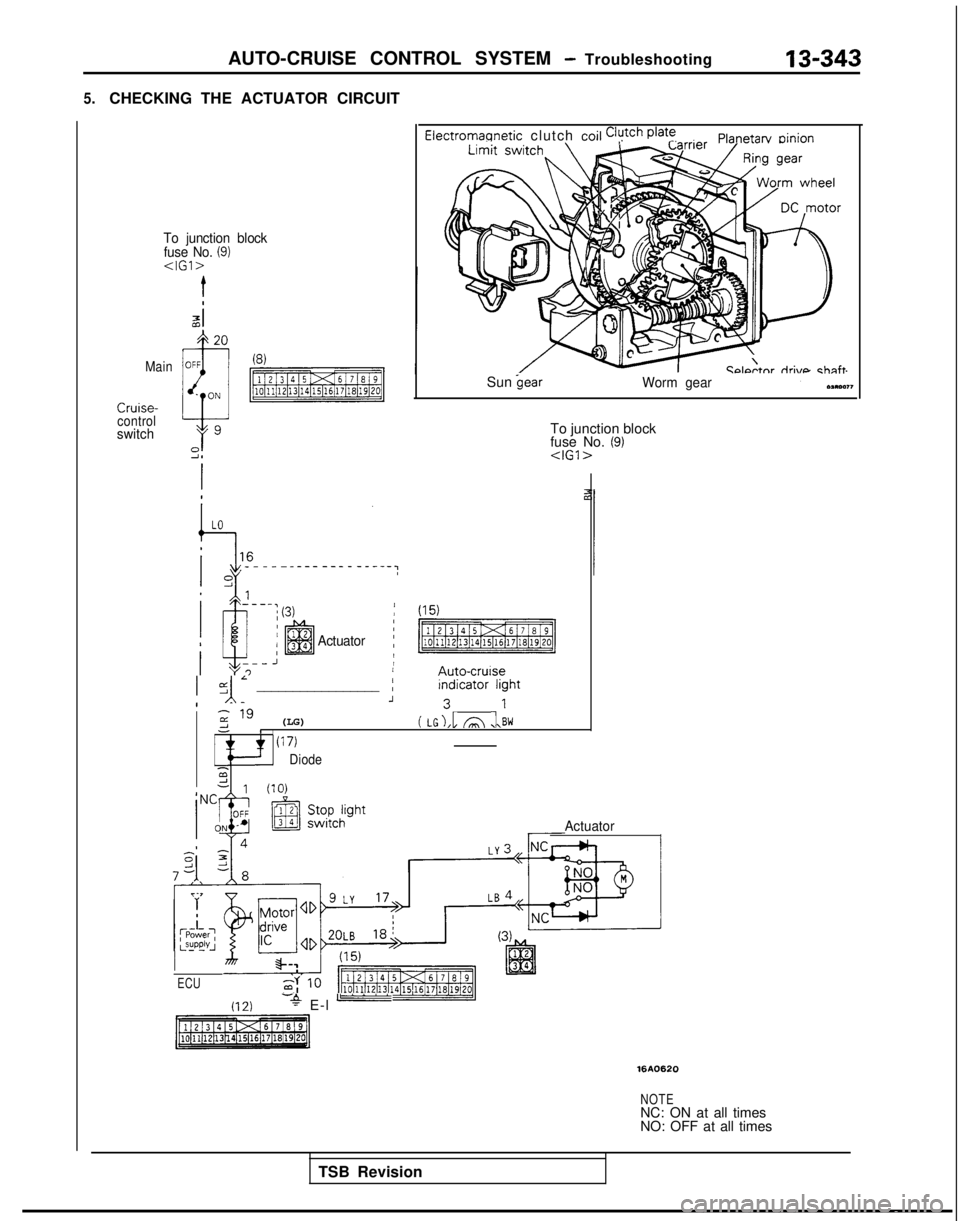
5.CHECKING THE ACTUATOR CIRCUIT
Electromannetic clutch coil Clutch @at’!Planetarv oinion
To junction block
fuse No. (9)
Ccdtnr riri\mchnftMainSun
control
switchTo junction block
fuse No. (9)
Actuator
/ (15)
p$%Emig
jyl; _________________ ;F:;;:ght
z " (LG)-1( LG),l A ,l\BWI(17)
Diode2d 111n\
Actuator
ECU
(12)-+ E-l -
1610620
NOTENC: ON at all times
NO: OFF at all times
TSB Revision
Page 486 of 1273
13-344AUTO-CRUISE CONTROL SYSTEM - Troubleshooting
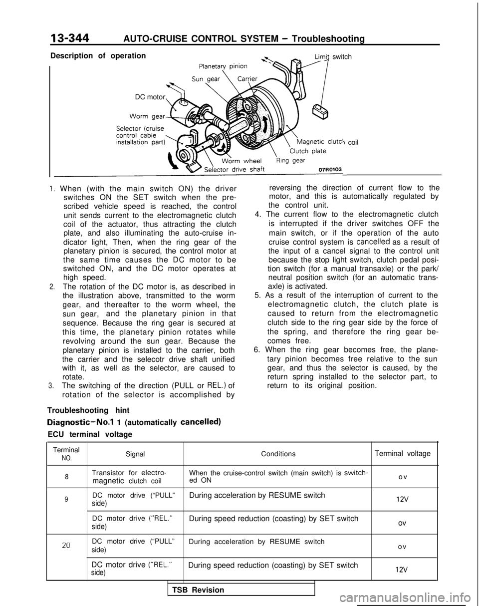
Description of operation
* -LimA switch
DC motor
7 coil
-
1. When (with the main switch ON) the driver switches ON the SET switch when the pre-
scribed vehicle speed is reached, the control
unit sends current to the electromagnetic clutch
coil of the actuator, thus attracting the clutch plate, and also illuminating the auto-cruise in-
dicator light, Then, when the ring gear of the planetary pinion is secured, the control motor at
the same time causes the DC motor to be
switched ON, and the DC motor operates at high speed.
2.The rotation of the DC motor is, as described in
the illustration above, transmitted to the worm
gear, and thereafter to the worm wheel, the
sun gear, and the planetary pinion in that
sequence. Because the ring gear is secured at
this time, the planetary pinion rotates while revolving around the sun gear. Because the
planetary pinion is installed to the carrier, both
the carrier and the selecotr drive shaft unified
with it, as well as the selector, are caused to rotate.
3.The switching of the direction (PULL or REL.) of
rotation of the selector is accomplished by reversing the direction of current flow to the
motor, and this is automatically regulated by
the control unit.
4. The current flow to the electromagnetic clutch
is interrupted if the driver switches OFF the
main switch, or if the operation of the auto
cruise control system is
cancelled as a result of
the input of a cancel signal to the control unit because the stop light switch, clutch pedal posi-
tion switch (for a manual transaxle) or the park/ neutral position switch (for an automatic trans-
axle) is activated.
5. As a result of the interruption of current to the
electromagnetic clutch, the clutch plate is
caused to return from the electromagnetic
clutch side to the ring gear side by the force of
the spring, and therefore the ring gear be-
comes free.
6. When the ring gear becomes free, the plane-
tary pinion becomes free relative to the sungear, and thus the selector is caused, by the
return spring installed to the selector part, to
return to its original position.
Troubleshooting hint
Diagnostic-No.1 1 (automatically cancelled)
ECU terminal voltage
Terminal
NO.Signal ConditionsTerminal voltage
8Transistor for electro-When the cruise-control switch (main switch) is switch-
magnetic clutch coiled ON o
v
9DC motor drive (“PULL”
During acceleration by RESUME switch
side) 12v
DC motor drive (“REL.”
During speed reduction (coasting) by SET switch
side)ov
20DC motor drive (“PULL” During acceleration by RESUME switch
side) o
v
DC motor drive (“REL.”
During speed reduction (coasting) by SET switch
side) 12v
TSB Revision
Page 487 of 1273
AUTO-CRUISE CONTROL SYSTEM - Troubleshooting13-345
6-1. CHECKING THE STOP LIGHT SWITCH CIRCUIT
Battery
7Tco
A
9%6
I-
(GO) :
To stop light
NOTENC: ON at all timesNO: OFF at all times
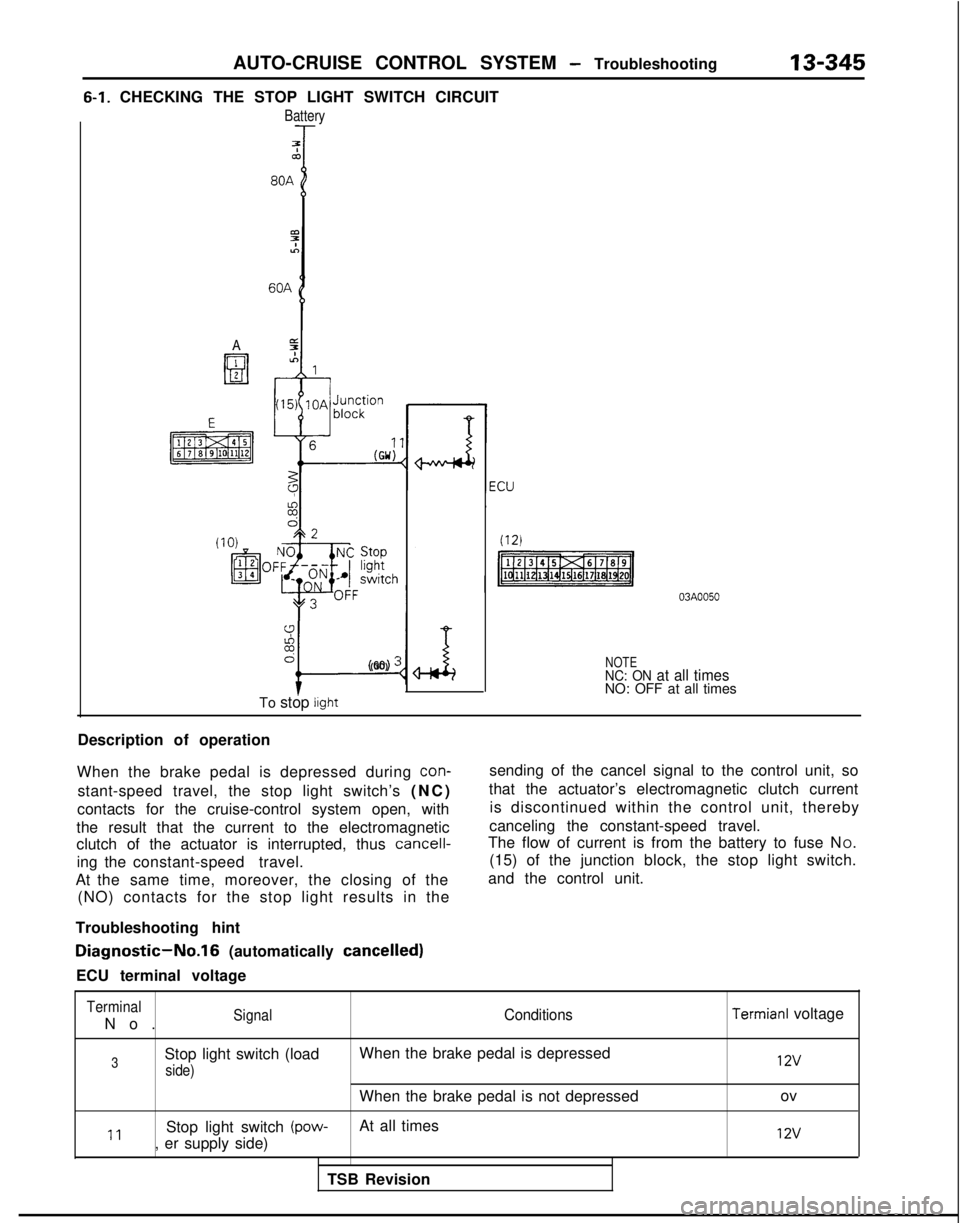
Description of operation
When the brake pedal is depressed during
con-
stant-speed travel, the stop light switch’s (NC
)
contacts for the cruise-control system open, with
the result that the current to the electromagnetic
clutch of the actuator is interrupted, thus
cancell-
ing the constant-speed travel.
At the same time, moreover, the closing of the (NO) contacts for the stop light results in the
Troubleshooting hint sending of the cancel signal to the control unit, so
that the actuator’s electromagnetic clutch current is discontinued within the control unit, thereby
canceling the constant-speed travel.
The flow of current is from the battery to fuse N O.
(15) of the junction block, the stop light switch.
and the control unit.
Diagnostic-No.16 (automatically cancelled)
ECU terminal voltage
Terminal
No
.
SignalConditions
3Stop light switch (load
When the brake pedal is depressed
side)
When the brake pedal is not depressed
11Stop light switch (pow-At all times
, er supply side)
TSB Revision
Termianl voltage 12v
ov
12v
Page 488 of 1273
13-346AUTO-CRUISE CONTROL SYSTEM - Troubleshooting6-2.
CHECKING THE PARK/NEUTRAL POSITION SWITCH CIRCUIT
ECU
-I
J
(12)
2mi
Park/neutral
position
switch
zc:
1
&
A
I
3pry
iz,:
T
3qpIII
1 ? 3;m456
/I
Starter motor
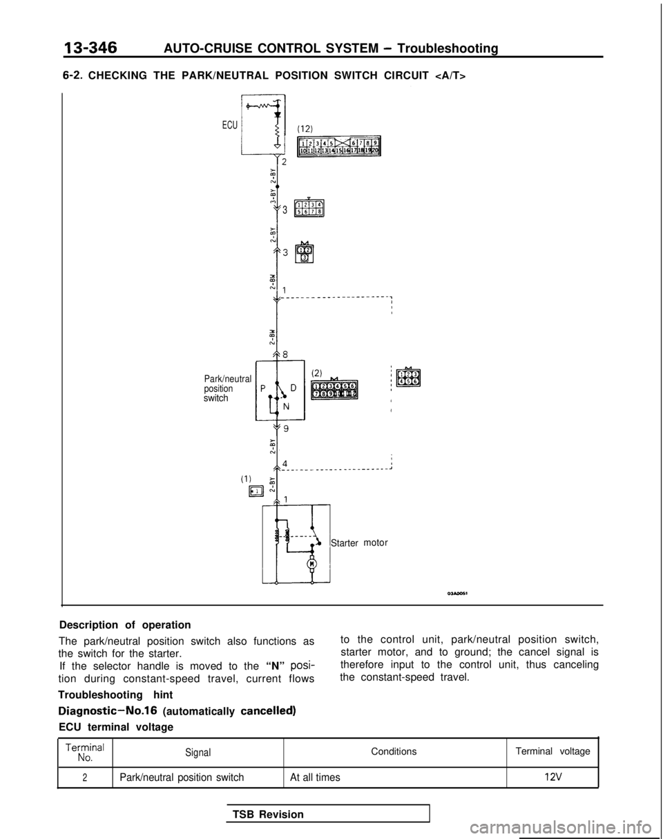
to the control unit, park/neutral position switch,
starter motor, and to ground; the cancel signal is
therefore input to the control unit, thus canceling
the constant-speed travel.
Description of operation
The park/neutral position switch also functions as
the switch for the starter.
If the selector handle is moved to the “N” posi-
tion during constant-speed travel, current flows
Troubleshooting hint
Diagnostic-No.16 (automatically cancelled)
ECU terminal voltage
Terra’Signal
2Park/neutral position switch At all times
ConditionsTerminal voltage
12v
TSB Revision
Page 489 of 1273
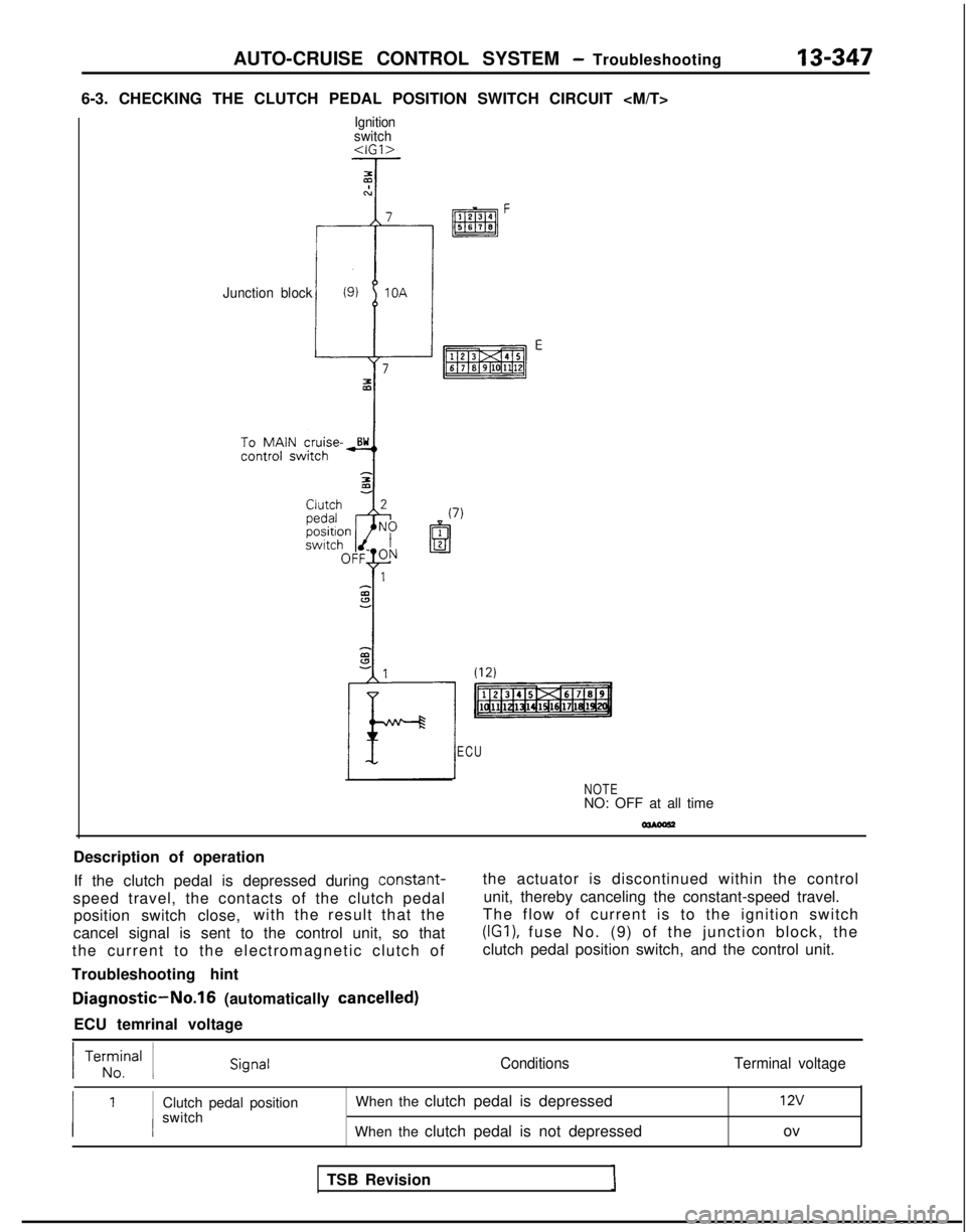
AUTO-CRUISE CONTROL SYSTEM - Troubleshooting13-347
6-3. CHECKING THE CLUTCH PEDAL POSITION SWITCH CIRCUIT
Ignition
switch
Junction block
ECU
NOTENO: OFF at all time
Description of operation If the clutch pedal is depressed during constant-
speed travel, the contacts of the clutch pedal position switch close, with the result that the
cancel signal is sent to the control unit, so that
the current to the electromagnetic clutch of
Troubleshooting hint
Diagnostic-No.16 (automatically cancelled)
ECU temrinal voltage the actuator is discontinued within the control
unit, thereby canceling the constant-speed travel.
The flow of current is to the ignition switch (IGI),
fuse No. (9) of the junction block, the
clutch pedal position switch, and the control unit.
/ Te;z,nal 1Conditions Terminal voltage
Clutch pedal position
switch When the clutch pedal is depressed
When the clutch pedal is not depressed12v
ov
TSB Revision
Page 490 of 1273
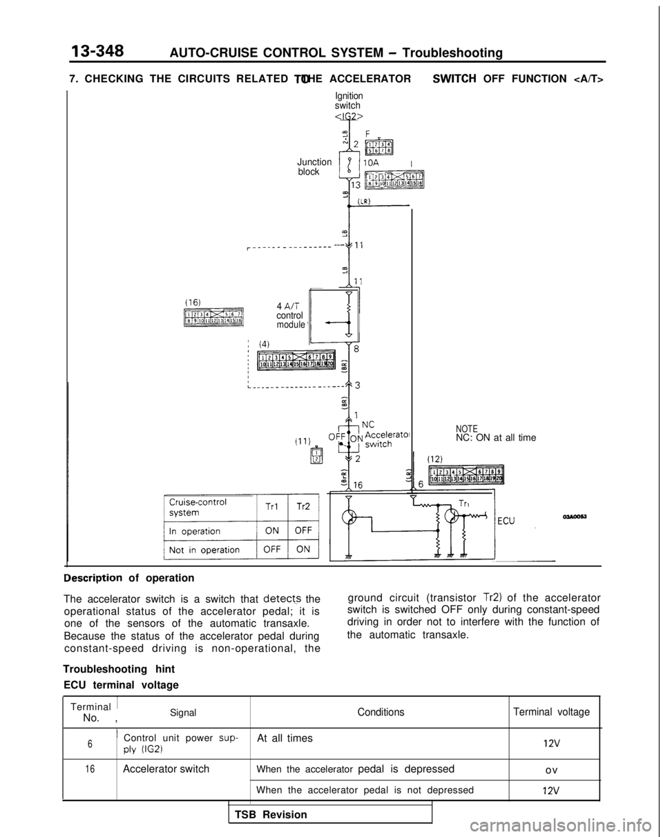
13-348AUTO-CRUISE CONTROL SYSTEM - Troubleshooting
7. CHECKING THE CIRCUITS RELATED TO THE ACCELERATOR SWITCH
OFF FUNCTION
(16)
[ml
Ignition
switch
Junction
block
r------_--- ___--- ---
4
A/T
control
module
NOTENC: ON at all time Iescription
of operation
The accelerator switch is a switch that
detect-s the
operational status of the accelerator pedal; it is one of the sensors of the automatic transaxle.
Because the status of the accelerator pedal during constant-speed driving is non-operational, the ground circuit (transistor Tr2) of the accelerator
switch is switched OFF only during constant-speed
driving in order not to interfere with the function of
the automatic transaxle.
Troubleshooting hint ECU terminal voltage
Terminal
1
No. , SignalConditions
Terminal voltage
6’ Control unit power sup-
At all times12vply (IG2)
16
Accelerator switch When the accelerator pedal is depressed
o
v
When the accelerator pedal is not depressed
12v
TSB Revision