MITSUBISHI GALANT 1989 Service Repair Manual
Manufacturer: MITSUBISHI, Model Year: 1989, Model line: GALANT, Model: MITSUBISHI GALANT 1989Pages: 1273, PDF Size: 37.62 MB
Page 871 of 1273
REAR AXLE
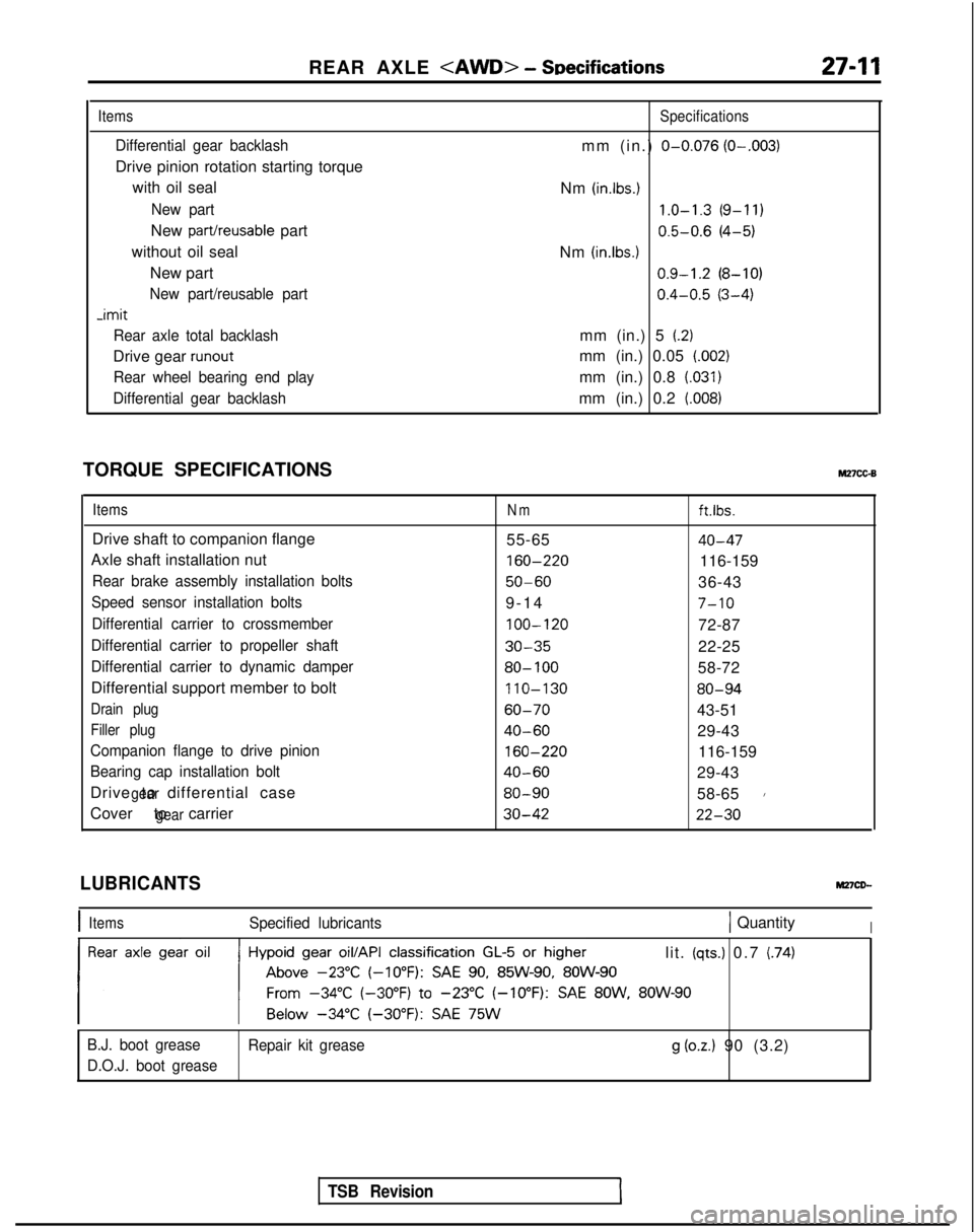
Items
Differential gear backlash
Drive pinion rotation starting torque
with oil seal
New part
New part/reusable part
without oil seal New part
New part/reusable part -imit
Rear axle total backlash
Drive gear runout
Rear wheel bearing end play
Differential gear backlash
Specifications
mm (in.) O-0.076 (O-.003)
Nm (in.lbs.) 1.0-1.3
(9-11)
0.5-0.6
(4-5)
Nm
(in.lbs.1 0.9-1.2
(8-10)
0.4-0.5
(3-4)
mm (in.) 5
(2)
mm (in.) 0.05 (.002)
mm (in.) 0.8 (.031)
mm (in.) 0.2 (008)
TORQUE SPECIFICATIONSM27cc-B
ItemsNmft.lbs.
Drive shaft to companion flange 55-6540-47
Axle shaft installation nut 160-220
116-159
Rear brake assembly installation bolts50-6036-43
Speed sensor installation bolts9-1
4
7-10
Differential carrier to crossmember
100-120
72-87
Differential carrier to propeller shaft30-3522-25
Differential carrier to dynamic damper80- 10058-72
Differential support member to bolt 110-130
80-94
Drain plug60-7043-51
Filler plug40-6029-43
Companion flange to drive pinion
160-220
116-159
Bearing cap installation bolt40-6029-43
Drive to differential case
gear80-9058-651
Cover to carriergear30-4222-30
TSB Revision
LUBRICANTS
IItemsSpecified lubricants1 QuantityI
lit. (qts.) 0.7 (74)
B.J. boot grease Repair kit grease
g (oz.) 90 (3.2)
D.O.J. boot grease
Page 872 of 1273
27-12REAR AXLE
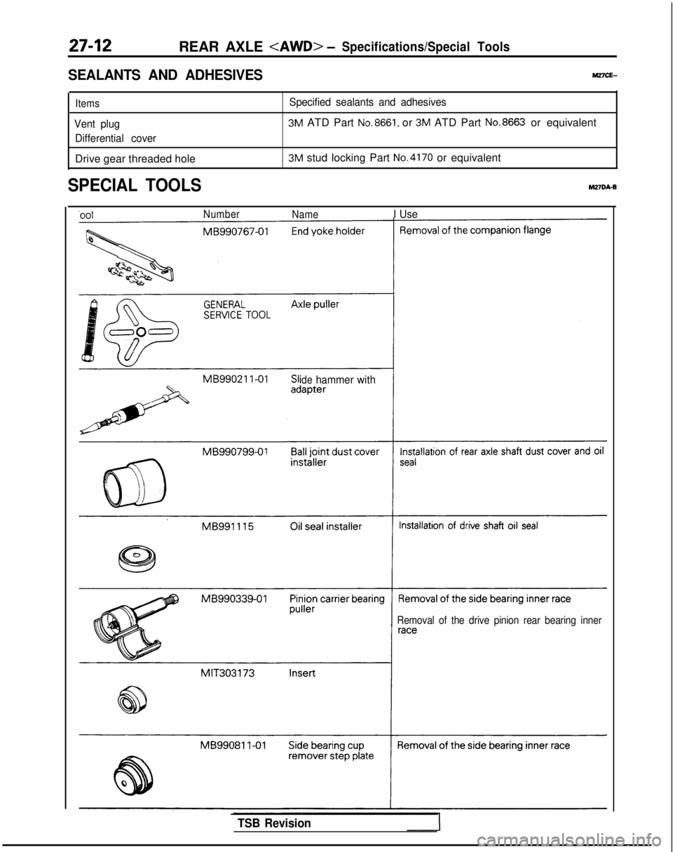
SEALANTS AND ADHESIVESMZICE-
ItemsSpecified sealants and adhesives
Vent plug
3M ATD Part No.8661, or 3M ATD Part No.8663 or equivalent
Differential cover
Drive gear threaded hole3M stud locking Part No.4170 or equivalent
SPECIAL TOOLSM27DA-B
‘nnlNumber NameI Use
idehammer with
Removal of the drive pinion rear bearing inner
TSB Revision
Page 873 of 1273
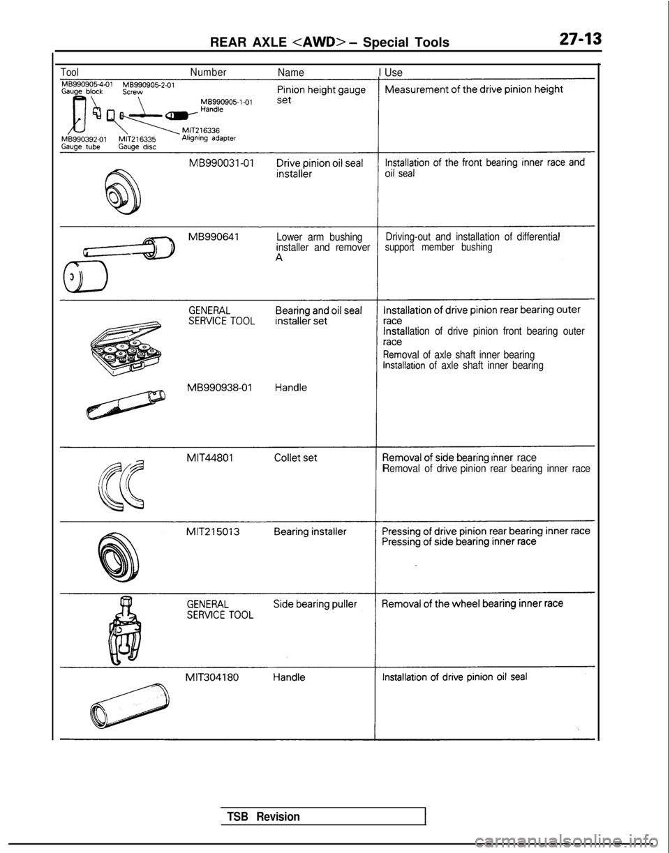
ToolNumberNameI Use MB990905-l-01
Lower arm bushing
Driving-out and installation of differential
installer and removersupport member bushing
MB990938-01 llation of drive pinion front bearing outer
oval of axle shaft inner bearing
llation of axle shaft inner bearing
eanng Inner raceRemoval of drive pinionrear bearing inner race
REAR AXLE
TSB Revision
Page 874 of 1273
27-14REAR AXLE
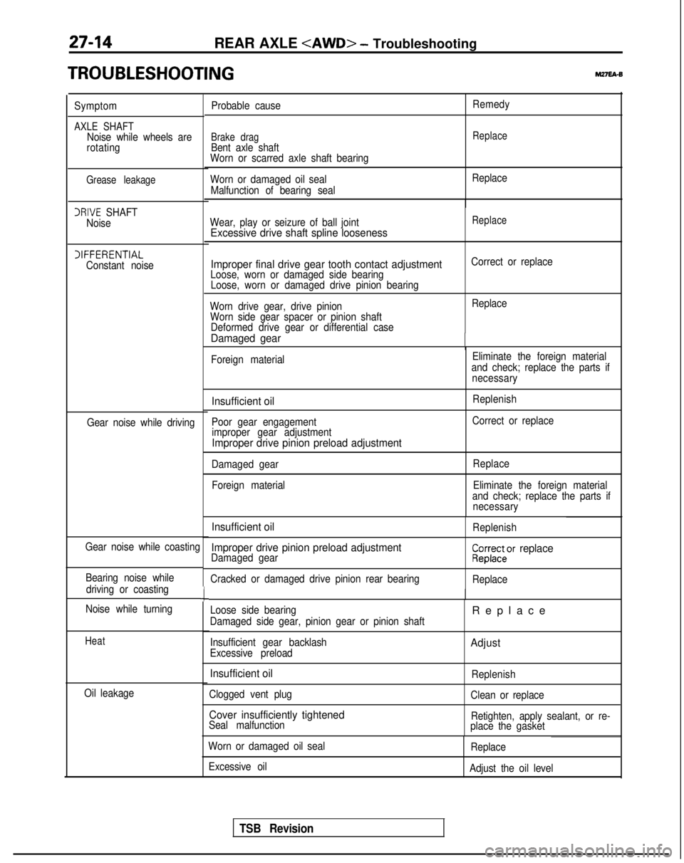
rROUBLESHOOTlNG
Symptom
AXLE SHAFTNoise while wheels are
rotating
Grease leakage
IRIVE SHAFT
Noise
IIFFERENTIAL Constant noise
Gear noise while driving
Gear noise while coasting Bearing noise while driving or coasting
Noise while turning
Heat
Oil leakage
c
Probable cause
Brake dragBent axle shaft
Worn or scarred axle shaft bearing
Worn or damaged oil seal
Malfunction of bearing seal Remedy
Replace
Replace
Wear, play or seizure of ball joint
Excessive drive shaft spline looseness
Replace
Improper final drive gear tooth contact adjustmentLoose, worn or damaged side bearing Loose, worn or damaged drive pinion bearing Correct or replace
Worn drive gear, drive pinion Worn side gear spacer or pinion shaft Deformed drive gear or differential case
Damaged gear -
Replace
Foreign material Eliminate the foreign material
and check; replace the parts if necessary
Insufficient oil
Poor gear engagementimproper gear adjustment
Improper drive pinion preload adjustment
Replenish
Correct or replace
Damaged gear Foreign material Replace
Eliminate the foreign material
and check; replace the parts if necessary
Insufficient oil
Improper drive pinion preload adjustment
Damaged gear
Cracked or damaged drive pinion rear bearing ReplenishCZ23rar2cr replace
Replace
Loose side bearing
Damaged side gear, pinion gear or pinion shaft
Insufficient gear backlash
Excessive preload
Insufficient oil
Clogged vent plug
Cover insufficiently tightenedSeal malfunction
Replac
e
Adjust
Replenish
Clean or replace
Retighten, apply sealant, or re-
place the gasket
Worn or damaged oil seal
Excessive oil Replace
Adjust the oil level
TSB Revision
Page 875 of 1273
REAR AXLE
Matina marks/I
1
SERVICE ADJUSTMENT PROCEDURES
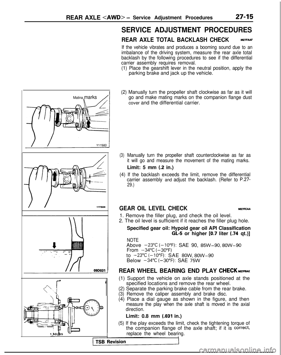
REAR AXLE TOTAL BACKLASH CHECKMZ’IFAAF
If the vehicle vibrates and produces a booming sound due to an
imbalance of the driving system, measure the rear axle total
backlash by the following procedures to see if the differential
carrier assembly requires removal.
(1) Place the gearshift lever in the neutral position, apply the
parking brake and jack up the vehicle.
(2) Manually turn the propeller shaft clockwise as far as it will go and make mating marks on the companion flange dust
cover and the differential carrier.
(3)Manually turn the propeller shaft counterclockwise as far as
it will go and measure the movement of the mating marks.
Limit: 5 mm (.2 in.)
(4) If the backlash exceeds the limit, remove the differential carrier assembly
and adjust the backlash. (Refer to P.27-
29.)
GEAR OIL LEVEL CHECKM27FcAA
1. Remove the filler plug, and check the oil level.
2. The oil level is sufficient if it reaches the filler plug hole.
Specified gear oil: Hypoid gear oil API Classification
GL-5 or higher [0.7 liter (.74 qt.)]
NOTE
Above -23°C
(-10°F):
SAE 90, 85W-90,
8OW-90
From -34°C
(-30°F)
to
-23°C (-10°F): SAE 8OW, 8OW-90
Below -34°C
(-30°F):
SAE
75W
REAR WHEEL BEARING END PLAY CHECK~FBAE
(1) Support the vehicle on axle stands positioned at the
specified locations and remove the rear wheel.
(2) Separate the parking brake cable from the rear brake.
(3) Remove the caliper assembly and brake disc.
(4) Place a dial gauge as shown in the figure, and then
measure the play when the axle shaft is moved in the axial
direction.
Limit: 0.8 mm (.031 in.)
(5) If the play exceeds the limit, check the tightening torque of
the companion flange of the axle shaft; if it is correct,
replace the wheel bearing.llA0065 IJ d-
Page 876 of 1273
REAR AXLE
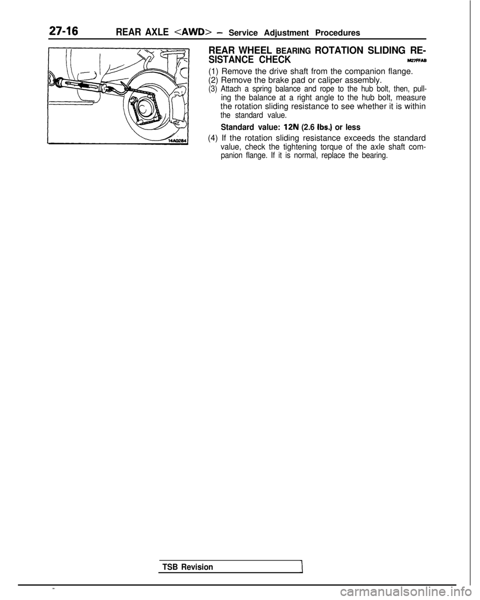
REAR WHEEL BEARING ROTATION SLIDING RE-
SISTANCE CHECKnnnFFA6
(1) Remove the drive shaft from the companion flange.
(2) Remove the brake pad or caliper assembly.
(3) Attach a spring balance and rope to the hub bolt, then, pull-
ing the balance at a right angle to the hub bolt, measure
the rotation sliding resistance to see whether it is within
the standard value.
Standard value: 12N (2.6 Ibs.) or less
(4) If the rotation sliding resistance exceeds the standard
value, check the tightening torque of the axle shaft com-
panion flange. If it is normal, replace the bearing.
TSB Revision
Page 877 of 1273
REAR AXLE
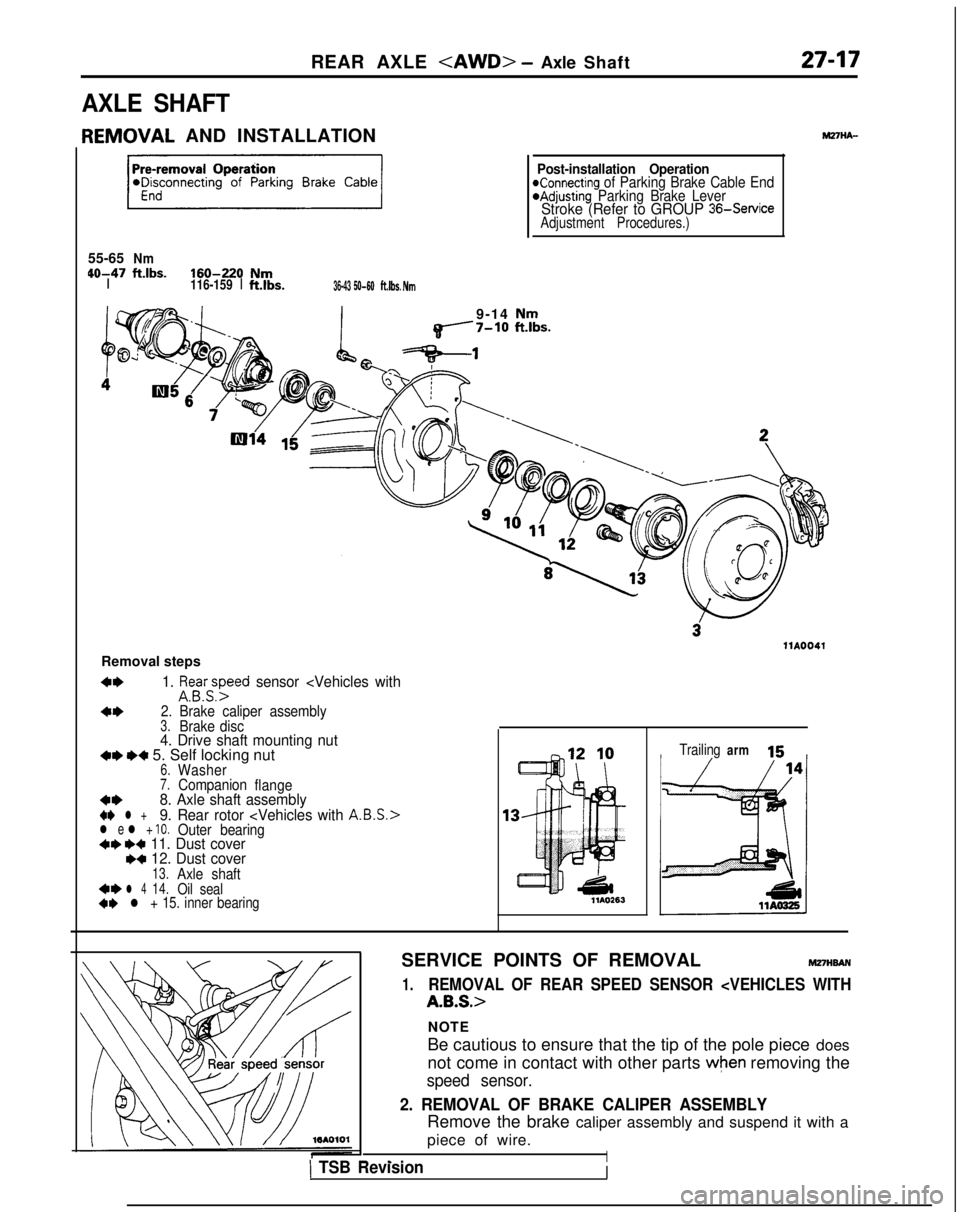
AXLE SHAFT
IEMOVAL
AND INSTALLATION
55-65
Nm 40-47
ftlbs.160-220NmI116-159
Ift.lbs.36-43 50-60ft.lbs. Nm
Post-installation OperationKonnecting of Parking Brake Cable End@Adjusting Parking Brake LeverStroke (Refer to GROUP 36-Service
Adjustment Procedures.)
9-14 Nmq------7-10 ft.lbs.
llA0041
Removal steps
4*1. ifsa.yyed sensor
arm 15
SERVICE POINTS OF REMOVAL
MmwAN
1.REMOVAL OF REAR SPEED SENSOR
NOTE
Be cautious to ensure that the tip of the pole piece does
not come in contact with other parts
when removing the
speed sensor.
2. REMOVAL OF BRAKE CALIPER ASSEMBLY
Remove the brake caliper assembly and suspend it with a
piece of wire.
I- _,1 TSB RevisionI
Page 878 of 1273
27-18REAR AXLE
-MB990938-01
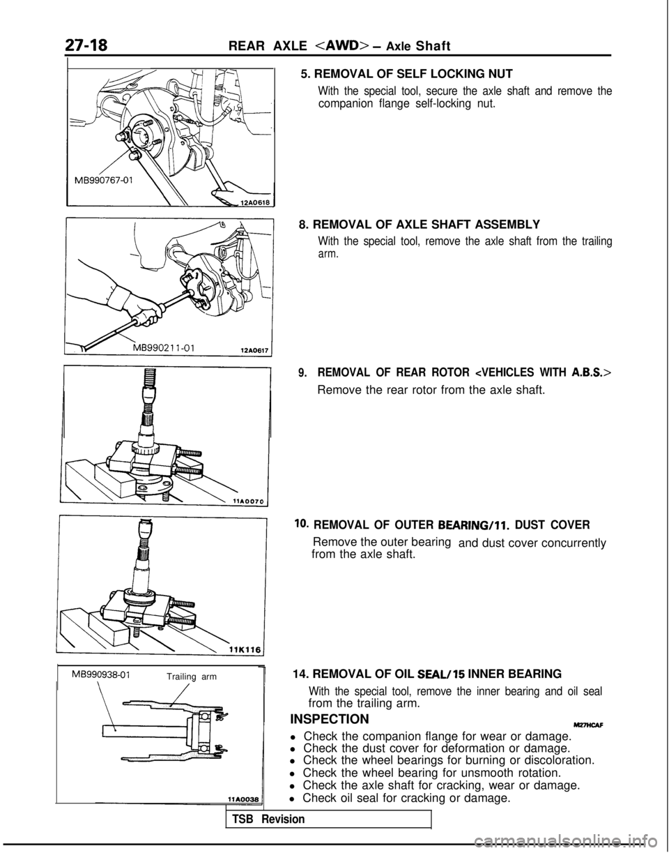
Trailing arm 5. REMOVAL OF SELF LOCKING NUT
With the special tool, secure the axle shaft and remove the
companion flange self-locking nut.
8. REMOVAL OF AXLE SHAFT ASSEMBLY
With the special tool, remove the axle shaft from the trailing
arm.
9.REMOVAL OF REAR ROTOR
Remove the rear rotor from the axle shaft.
10. REMOVAL OF OUTER BEARING/ll. DUST COVER
Remove the outer bearing
from the axle shaft. and dust cover concurrently
14. REMOVAL OF OIL
SEAL/15 INNER BEARING
With the special tool, remove the inner bearing and oil seal
from the trailing arm.
INSPECTION
M27wAF
l Check the companion flange for wear or damage.
l Check the dust cover for deformation or damage.
l Check the wheel bearings for burning or discoloration.
l Check the wheel bearing for unsmooth rotation.
l Check the axle shaft for cracking, wear or damage.
l Check oil seal for cracking or damage.
TSB Revision
Page 879 of 1273
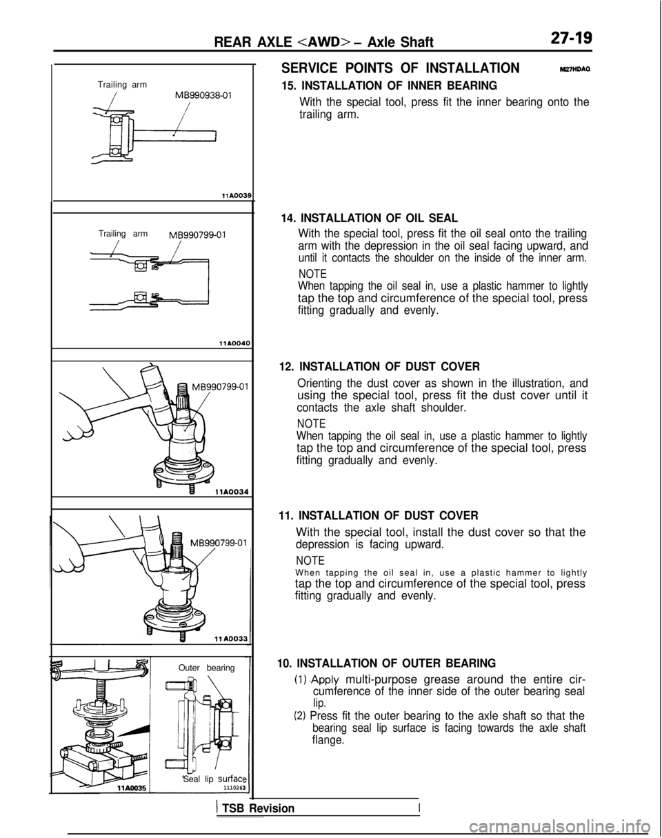
REAR AXLE
Trailing arm
/MB990938-01
Trailing arm MB990799-01
llAOO40
11 A0033
Outer bearing
Seal lip
surfac’111026
SERVICE POINTS OF INSTALLATIONW7HDAQ
15. INSTALLATION OF INNER BEARING
With the special tool, press fit the inner bearing onto the
trailing arm.
14. INSTALLATION OF OIL SEAL
With the special tool, press fit the oil seal onto the trailing
arm with the depression in the oil seal facing upward, and
until it contacts the shoulder on the inside of the inner arm.
NOTE
When tapping the oil seal in, use a plastic hammer to lightly
tap the top and circumference of the special tool, press
fitting gradually and evenly.
12. INSTALLATION OF DUST COVER
Orienting the dust cover as shown in the illustration, and
using the special tool, press fit the dust cover until it
contacts the axle shaft shoulder.
NOTE
When tapping the oil seal in, use a plastic hammer to lightly
tap the top and circumference of the special tool, press
fitting gradually and evenly.
11. INSTALLATION OF DUST COVER
With the special tool, install the dust cover so that the
depression is facing upward.
NOTE
When tapping the oil seal in, use a plastic hammer to lightl
y
tap the top and circumference of the special tool, press
fitting gradually and evenly.
10. INSTALLATION OF OUTER BEARING
(1) .Apply multi-purpose grease around the entire cir-
cumference of the inner side of the outer bearing seal
lip.
(2) Press fit the outer bearing to the axle shaft so that the
bearing seal lip surface is facing towards the axle shaft
flange.
1 TSB RevisionI
Page 880 of 1273
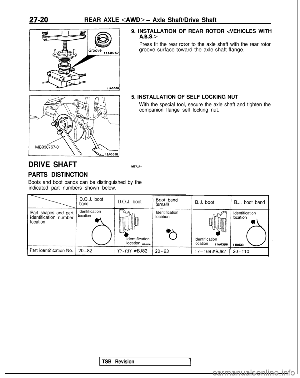
27-20REAR AXLE
DRIVE SHAFT
PARTS DISTINCTION
9. INSTALLATION OF REAR ROTOR
Press fit the rear rot,or to the axle shaft with the rear rotor
groove surface toward the axle shaft flange.
5. INSTALLATION OF SELF LOCKING NUT
With the special tool, secure the axle shaft and tighten the companion flange self locking nut.
M27JA-
Boots and boot bands can be distinguished by the
indicated part numbers shown below.
TSB Revision
Part shapesidentificationlocation
D.O.J. bootband
Identification
location
D.O.J. boot
Identification B.J. boot
B.J. boot band
Identification
Identification
location
llAO356 ran
laenrirrcarlon 110.17-131 #BJ82) 20-83I 17-169#BJ82 ) 20-110