MITSUBISHI GALANT 1989 Service Repair Manual
Manufacturer: MITSUBISHI, Model Year: 1989, Model line: GALANT, Model: MITSUBISHI GALANT 1989Pages: 1273, PDF Size: 37.62 MB
Page 831 of 1273
26-1
FRONT AXLE
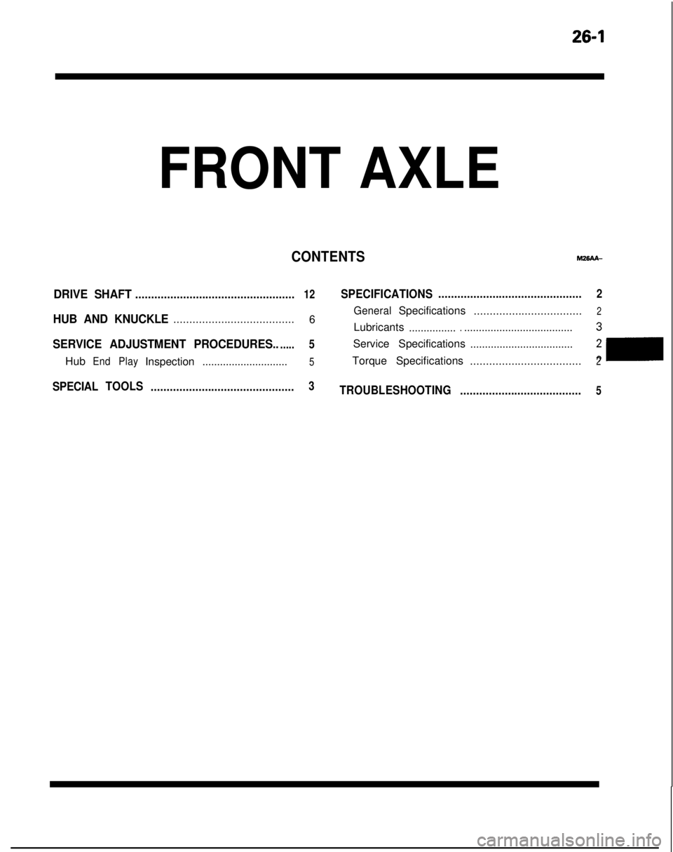
CONTENTS
DRIVE SHAFT..................................................12SPECIFICATIONS.............................................2
GeneralSpecifications
..................................2HUB AND KNUCKLE...................................... 6
Lubricants ......................................................3
SERVICE ADJUSTMENT PROCEDURES.......5Service Specifications ...................................
Hub
End PlayInspection5Torque Specifications2m............................. ...................................2
SPECIAL
TOOLS
.............................................3TROUBLESHOOTING ......................................5
Page 832 of 1273
26-2
SPECIFICATIONS
FRONT AXLE - Specifications
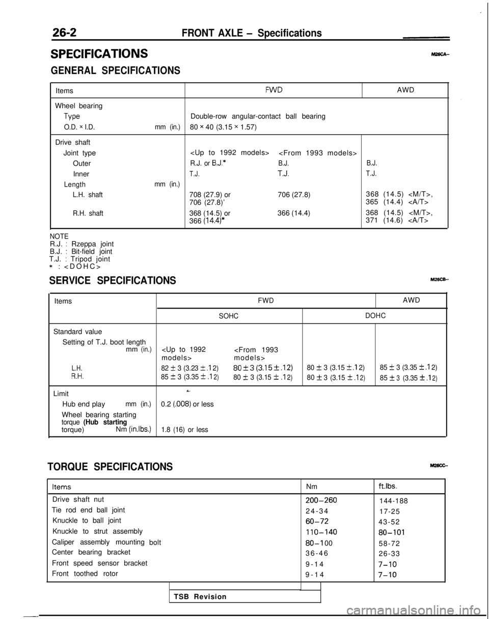
GENERAL SPECIFICATIONS
Items
Wheel bearing Type
O.D. x I.D.
Drive shaft
Joint type Outer
Inner
Length L.H. shaft
R.H. shaft
FWDAWD
Double-row angular-contact ball bearing
mm (in.)80 x 40 (3.15 x 1.57)
R.J. or B.J.*B.J. B.J.
T.J.T.J.T.J.
mm (in.)
708 (27.9) or
706 (27.8)368 (14.5)
706 (27.8)’ 365 (14.4)
368 (14.5) or 366 (14.4)368 (14.5)
366
(14.4)*371 (14.6)
NOTER.J. : Rzeppa joint
B.J. : Bit-field joint
T.J. : Tripod joint *:
>
SERVICE SPECIFICATIONS
ItemsFWDAWD
SOHC
DOHC
Standard value
Setting of T.J. boot length mm
(in.)
L.H.82 + 3 (3.23 k .I 2)80f3 (3.15f.12)80 + 3 (3.15 f .I 2)
85 f 3 (3.35 k .I 2)
R.H.85 III 3 (3.35 +
.I2)80 IL 3 (3.15 f.I2)80f3
(3.15f .I2)85f3(3.3531
.I2)
LimitX.
Hub end playmm (in.)0.2 (.008) or less
Wheel bearing starting
torque (Hub startingtorque) Nm (inlbs.)1.8 (16) or less
TORQUE SPECIFICATIONS
ItemsNmftlbs.
Drive shaft nut200-260144-188
Tie rod end ball joint 24-3
4
17-25
Knuckle to ball joint
60-7243-52
Knuckle to strut assembly
110-14080-101
Caliper assembly mounting bolt80-I 0058-72
Center bearing bracket 36-4
6
26-33
Front speed sensor bracket 9-14
7-10
Front toothed rotor9-1
4
7-10
TSB Revision
-_
Page 833 of 1273
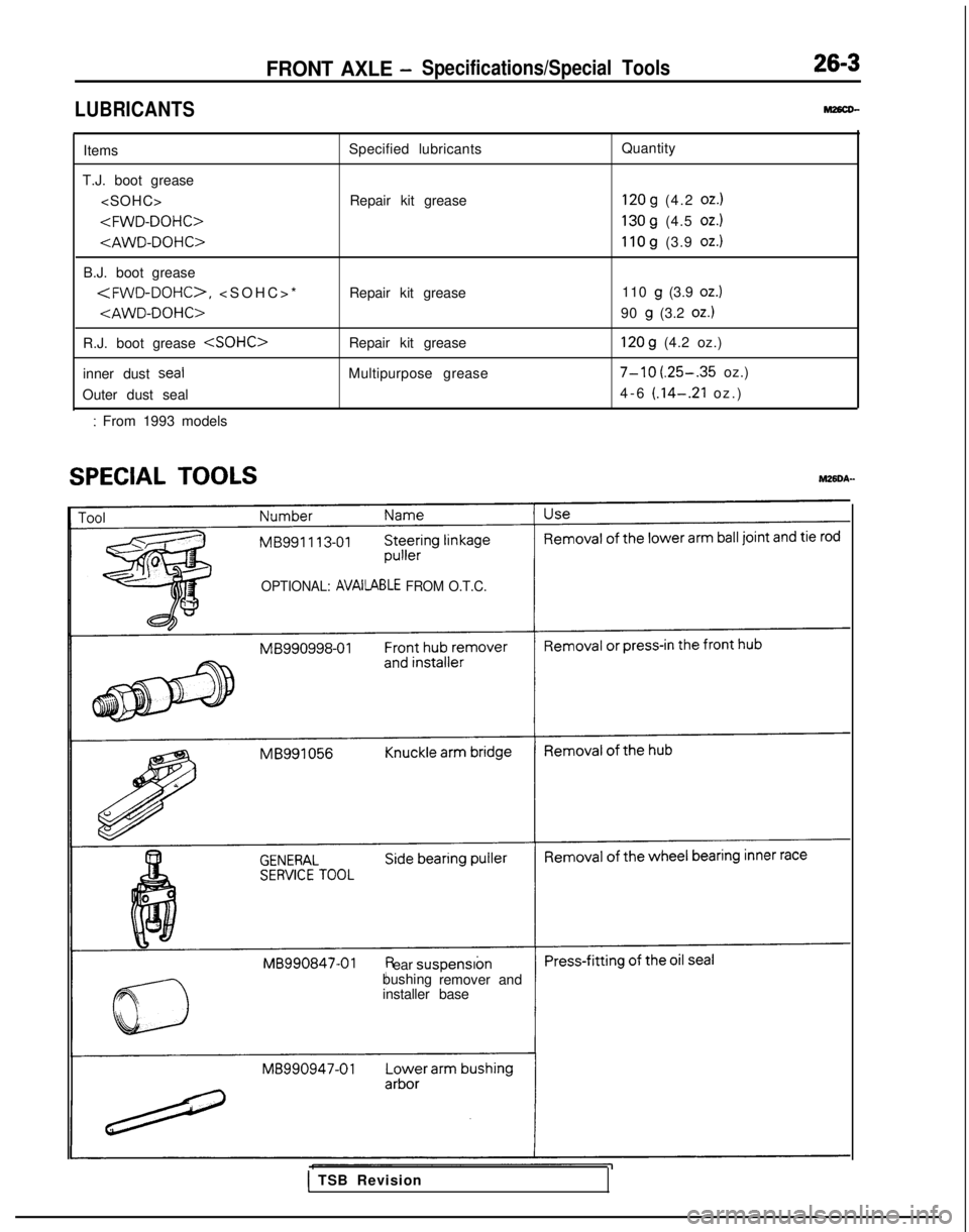
LUBRICANTS
FRONT AXLE -Specifications/Special Tools26-3
M26cD-
Items
T.J. boot grease
B.J. boot grease
*
R.J. boot grease
inner dust
seal
Outer dust seal
: From 1993 models Specified lubricants
Repair kit grease
Repair kit grease
Repair kit grease
Multipurpose grease Quantity
120 g (4.2 oz.)
130 g (4.5 oz.)
110 g (3.9 oz.)
110 g (3.9 oz.)
90 g (3.2 oz.)
120 g (4.2 oz.)
7-10 (.25-.35 oz.)
4-6
(.14-.21 oz.
)
SPECIAL TOOLSM26DA-
OPTIONAL: AVAilABLE FROM O.T.C.
ear
suspensron
bushing remover and
installer base
1 TSB Revision
Page 834 of 1273
26-4FRONT AXLE- Special Tools
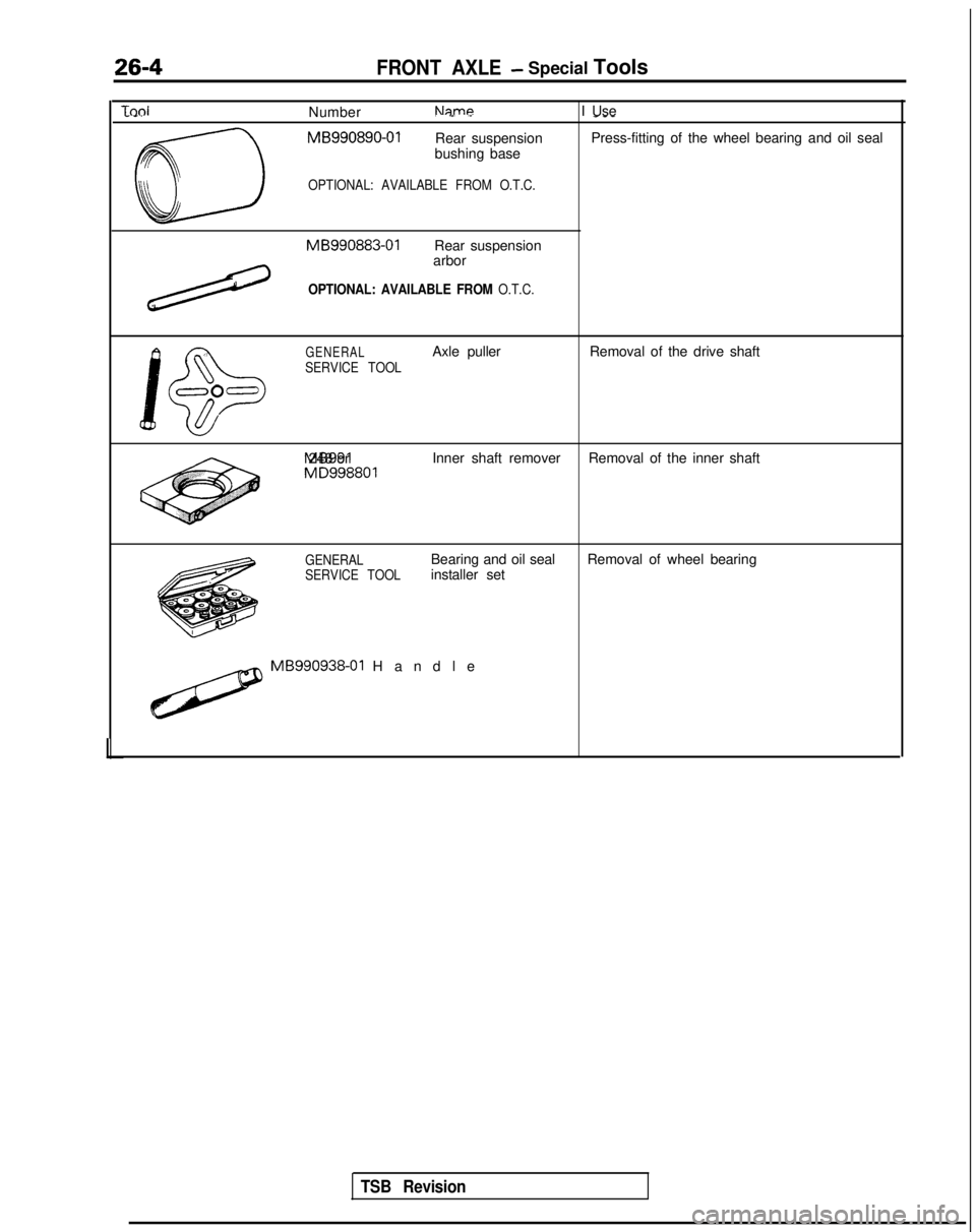
TdNumberNameI Use. .-. .------.
CD
MB990890-01
Rear suspension Press-fitting of the wheel bearing and oil seal
bushing base
OPTIONAL: AVAILABLE FROM O.T.C. MB990883-01
Rear suspension
arbor
/
OPTIONAL: AVAILABLE FROM O.T.C.
\
J!D
GENERALAxle puller Removal of the drive shaft
SERVICE TOOL
000
1 MB991 248 or
Inner shaft remover
Removal of the inner shaft MD998801
GENERAL
SERVICE TOOLBearing and oil seal
installer set
Removal of wheel bearing
H MB990938-01
Handle
TSB Revision
Page 835 of 1273
FRONT AXLE - Troubleshooting/Service Adjustment Procedures26-5
TROUBLESHOOTINGm6E6AA
Symptom
Vehicle pulls to one side Probable cause
Seizure of drive shaft ball joint
Abnormal wear, play or seizure of wheel bear-
ing
Remedy
Replace
Replace
Vibration
Shimmy Excessive noise Malfunction of front suspension or steering
Bend, damage or abnormal wear of drive shaft
Play in drive shaft and hub serration
Abnormal wear, play or seizure of wheel bear-
ing
Improper wheel alignment
Malfunction of front suspension or steering
Broken boot, grease leakage
Bend, damage or abnormal wear of drive shaft
Play of drive shaft and hub serration
Abnormal wear, play or seizure of center bearing Adjust or replace
Replace
Replace
Replace
Adjust or replace
Adjust or replace
Replace, repack grease
Replace
Replace
Replace
Abnormal wear, play or seizure of wheel bear-ing
Loose wheel nut
Malfunction of front suspension and steering
Replace
Retighten
Adjust or replace
SERVICE ADJUSTMENT
PROCEDURES
HUB END PLAY INSPECTIONM26FAAB
1. Jack up the vehicle and remove the front wheels.
2. Remove the disc brake caliper and suspend it with a wire.
(Refer to GROUP
35-Service Adjustment Procedures.)
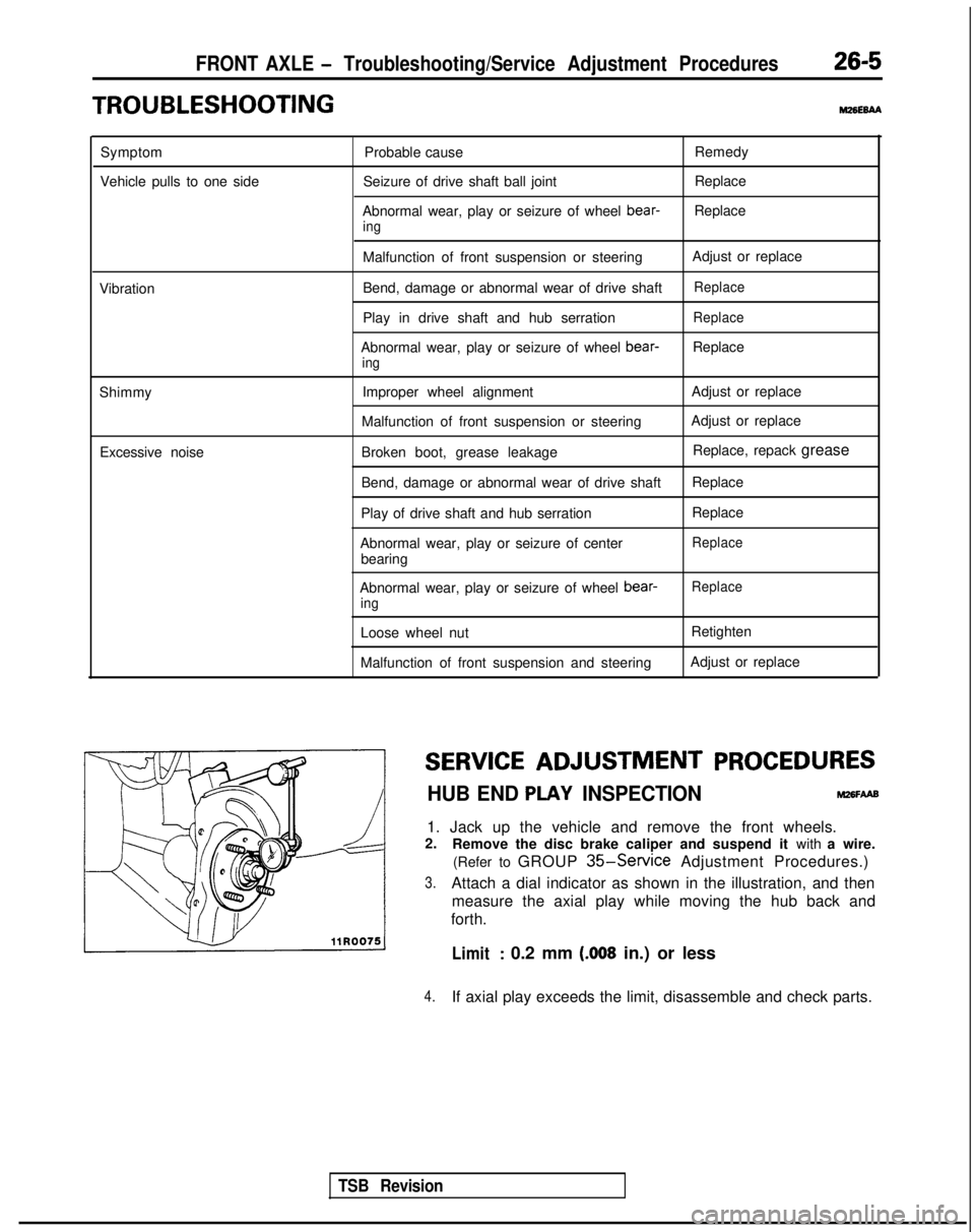
3.Attach a dial indicator as shown in the illustration, and then measure the axial play while moving the hub back and
forth.
Limit: 0.2 mm (.008 in.) or less
4.If axial play exceeds the limit, disassemble and check parts.
TSB Revision
Page 836 of 1273
26-6FRONT AXLE -Hub and Knuckle
HUB AND
KNUCKLE
REMOVAL AND INSTALLATION
SO-105 Nm
65-76 ft.lbs.
Vehicles with ACTIVE-ECS*’
80-100 Nm’\58-72 ftlbs.
9-14 Nm7- 10 ft.lbs.I
I
5rq :I
u
- 4. .i,'-
B860-72 Nm200-‘260 Nm
43-52
ft.lbs.IU-188 ft.lbs.
llA0121
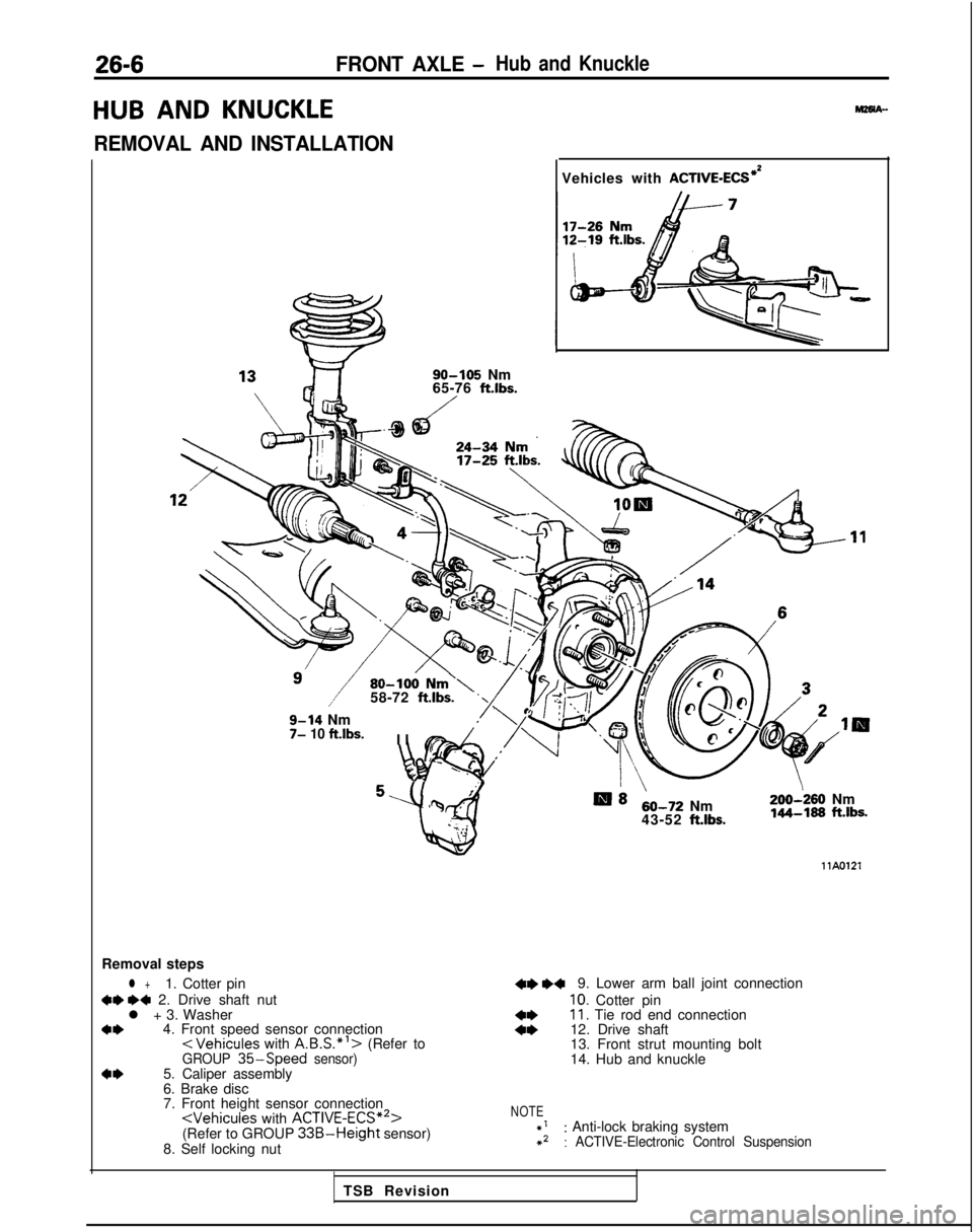
Removal steps
l +1. Cotter pin
+e I)+ 2. Drive shaft nut
l + 3. Washer
a*4. Front speed sensor connection< Vehicules
with A.B.S.*‘> (Refer toGROUP 35-Speed sensor)a*5. Caliper assembly
6. Brake disc
7. Front height sensor connection
(Refer to GROUP 33B-Height sensor)
8. Self locking nut
+e ~~9. Lower arm ball joint connection
10. Cotter pin
::11. Tie rod end connection
12. Drive shaft
13. Front strut mounting bolt
14. Hub and knuckle
NOTE
::: Anti-lock braking system: ACTIVE-Electronic Control Suspension
TSB Revision
Page 837 of 1273
FRONT AXLE - Hub and Knuckle26-7
SERVICE POINTS OF REMOVALM261sAE
2.
4.
REMOVAL OF DRIVE SHAFT NUTLoosen the drive shaft nut while the vehicle is on the floor
with the brakes applied.
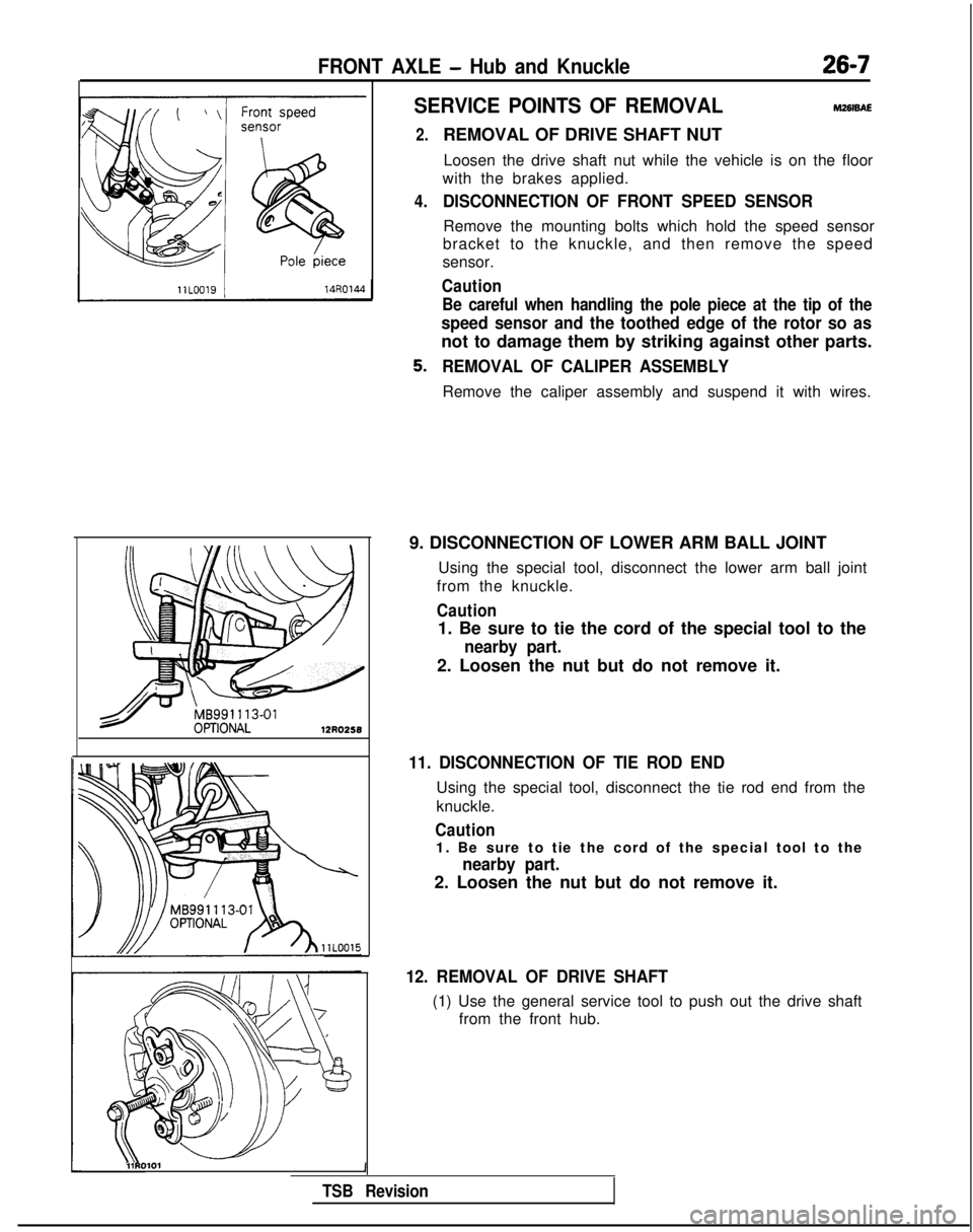
DISCONNECTION OF FRONT SPEED SENSOR
Remove the mounting bolts which hold the speed sensor
bracket to the knuckle, and then remove the speed
sensor.
Caution
Be careful when handling the pole piece at the tip of the
speed sensor and the toothed edge of the rotor so as
not to damage them by striking against other parts.
REMOVAL OF CALIPER ASSEMBLY
Remove the caliper assembly and suspend it with wires.
9. DISCONNECTION OF LOWER ARM BALL JOINT Using the special tool, disconnect the lower arm ball joint
from the knuckle.
Caution
1. Be sure to tie the cord of the special tool to the
nearby part.
2. Loosen the nut but do not remove it.
11. DISCONNECTION OF TIE ROD END
Using the special tool, disconnect the tie rod end from the
knuckle.
Caution
1. Be sure to tie the cord of the special tool to the
nearby part.
2. Loosen the nut but do not remove it.
12. REMOVAL OF DRIVE SHAFT
(1) Use the general service tool to push out the drive shaft from the front hub.
l\\11RO101 1
TSB Revision
Page 838 of 1273
26-8FRONT AXLE -Hub and Knuckle
Transaxle
Cotter pin
/
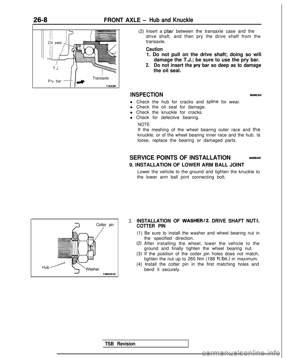
(2) Insert a pry bar between the transaxle case and the
drive shaft, and then pry the drive shaft from the
transaxle.
Caution
1. Do not pull on the drive shaft; doing so will
damage the T.J.; be sure to use the pry bar.
2.Do not insert the pry bar so deep as to damage
the oil seal.
INSPECTION
l Check the hub for cracks and spline
for wear.
l Check the oil seal for damage.
l Check the knuckle for cracks.
l Check for defective bearing.
NOTE
M26icAD
If the meshing of the wheel bearing outer race and the
knuckle, or of the wheel bearing inner race and the hub. is
loose, replace the bearing or damaged parts.
SERVICE POINTS OF INSTALLATIONMZMDAD
9. INSTALLATION OF LOWER ARM BALL JOINT
Lower the vehicle to the ground and tighten the knuckle to
the lower arm ball joint connecting bolt.
3.INSTALLATION OF WASHER/2. DRIVE SHAFT NUT/l.
COTTER PIN
(1) Be sure to install the washer and wheel bearing nut in
the specified direction.
(2) After installing the wheel, lower the vehicle to theground and finally tighten the wheel bearing nut.
(3) If the position of the cotter pin holes does not match, tighten the nut up to 260 Nm (188 ft.lbs.)
in maximum.
(4) Install the cotter pin in the first matching holes and bend it securely.
TSB Revision
Page 839 of 1273
FRONT AXLE - Hub and Knuckle26-9
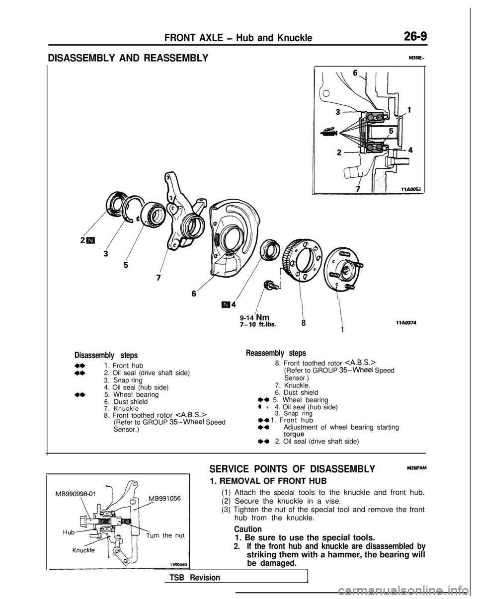
DISASSEMBLY AND REASSEMBLY
9-14 Nm7-10 ft.lbs.i !81
Disassembly steps
::
I. Front hub
2. Oil seal (drive shaft side)
3.Snapring
4. Oil seal (hub side)
4*5. Wheel bearing6.Dust shield
7. Knuckl
e
8. Front toothed rotor
(Refer to GROUP
35-Wheel Speed
Sensor.)
WA0374
Reassembly steps
8. Front toothed rotor
(Refer to GROUP 35-Wheel SpeedSensor.)7. Knuckle.
6. Dust shield
I)+ 5. Wheel bearingl +4. Oil seal (hub side) 3. Snap ring
I)+ 1. Front hubI)*Adiustment of wheel bearing starting torque
I)+2. Oil seal (drive shaft side)
SERVICE POINTS OF DISASSEMBLY
Mz6lFAM
1. REMOVAL OF FRONT HUB (1) Attach the special tools to the knuckle and front hub.
(2) Secure the knuckle in a vise.
(3) Tighten the nut of the special tool and remove the front hub from the knuckle.
Caution
1. Be sure to use the special tools.
2.If the front hub and knuckle are disassembled by
striking them with a hammer, the bearing will
be damaged.
TSB RevisionI
Page 840 of 1273
26-10FRONT AXLE -Hub and Knuckle
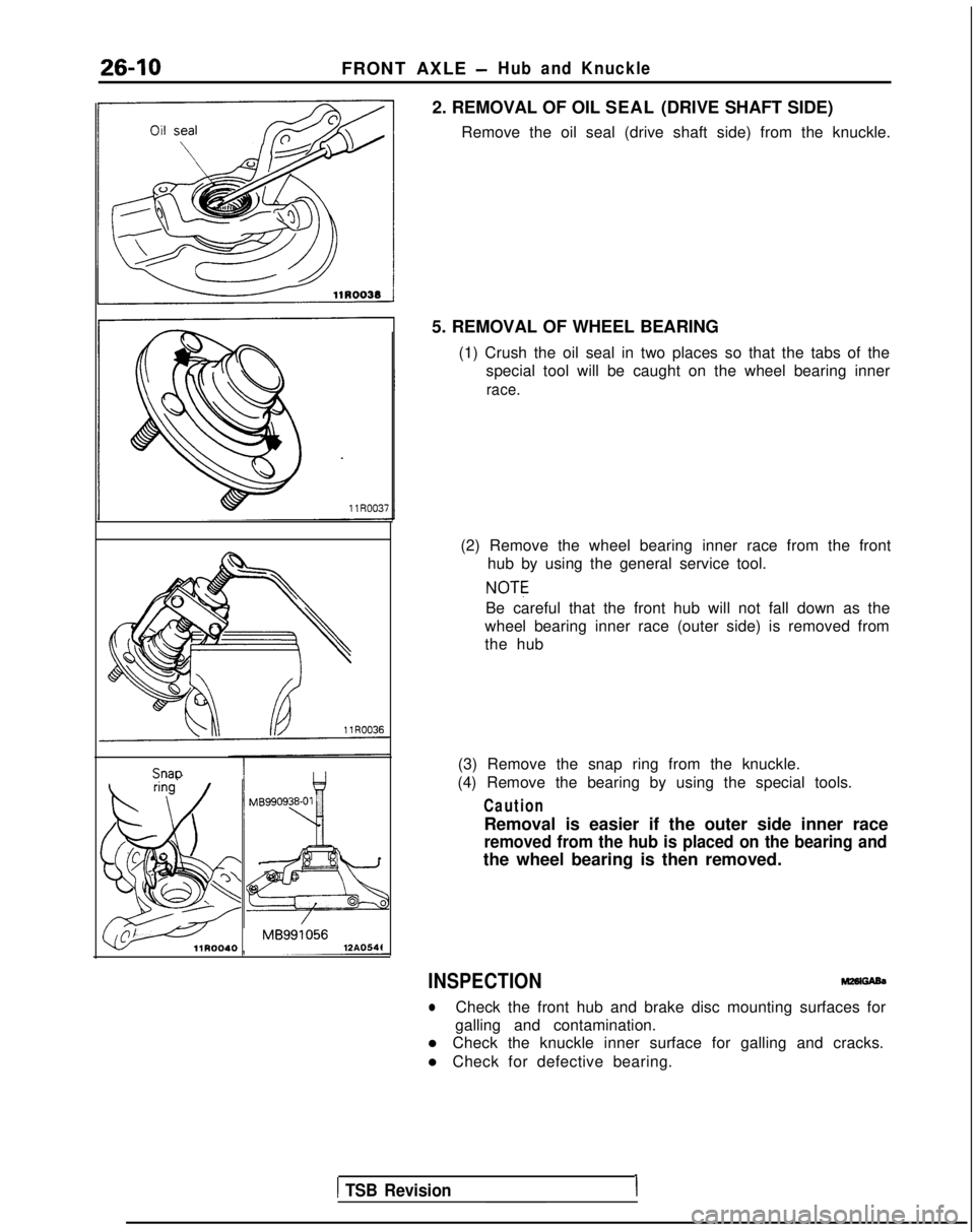
2. REMOVAL OF OIL SEAL (DRIVE SHAFT SIDE)Remove the oil seal (drive shaft side) from the knuckle. Snao
MB991056llROO40
12AO54t5. REMOVAL OF WHEEL BEARING
(1) Crush the oil seal in two places so that the tabs of the special tool will be caught on the wheel bearing inner
race.
(2) Remove the wheel bearing inner race from the fronthub by using the general service tool.
NOTE
Be careful that the front hub will not fall down as the
wheel bearing inner race (outer side) is removed from
the hub
(3) Remove the snap ring from the knuckle.
(4) Remove the bearing by using the special tools.
Caution
Removal is easier if the outer side inner race
removed from the hub is placed on the bearing and
the wheel bearing is then removed.
INSPECTION
lCheck the front hub and brake disc mounting surfaces for
galling and contamination.
l Check the knuckle inner surface for galling and cracks.
l Check for defective bearing.
1 TSB Revision1