MITSUBISHI GALANT 1989 Service Repair Manual
Manufacturer: MITSUBISHI, Model Year: 1989, Model line: GALANT, Model: MITSUBISHI GALANT 1989Pages: 1273, PDF Size: 37.62 MB
Page 931 of 1273
33A-10FRONT SUSPENSION - Lower Arm
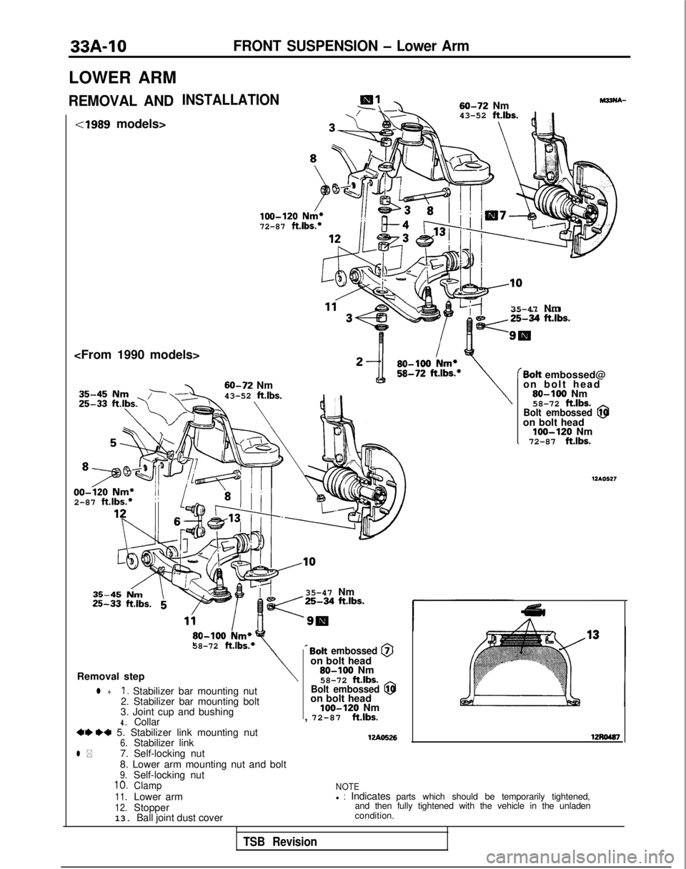
LOWER ARM
REMOVAL ANDINSTALLATION
cl989 models>
Nm
43-52 ft.lbs.
;>J$Jj!jQg&
3 -\
(/100-120 Nm*72-87 ft.lbs.*
35-47 Nm
60-72
Nm
43-52
ft.lbs. 00-320
Nm*
2-87 ft.lbs.*
35-47 Nm
/25-34 ft.lbs.
‘9s80-100
km*58-72 ft.lbs.*
Removal step
l +1. Stabilizer bar mounting nut
2. Stabilizer bar mounting bolt
3. Joint cup and bushing
4.Collar4* *a 5. Stabilizer link mounting nut6.Stabilizer linkl *7. Self-locking nut
8. Lower arm mounting nut and bolt
9.Self-locking nut10.Clamp11.Lower arm12.Stopper
13. Ball joint dust cover ’
Bolt embossed @on bolt head
80-100
Nm
58-72
ftlbs.Bolt embossed @on bolt headloo-120 Nm
, 72-87 ft.lbs.
WA0526
(Bolt embossed@
on bolt head
80-100 Nm
58-72 ftlbs.
Bolt embossed @on bolt headloo-120 Nm\ 72-87 ft.lbs.
12AO527
12Ro487
NOTEl : Indicates parts which should be temporarily tightened,
and then fully tightened with the vehicle in the unladen
condition.
TSB Revision
Page 932 of 1273
FRONT SUSPENSION - Lower Arm33A-11
12u00~0
TSB tieviSion
L/&tag and excessive p\ay.
.\
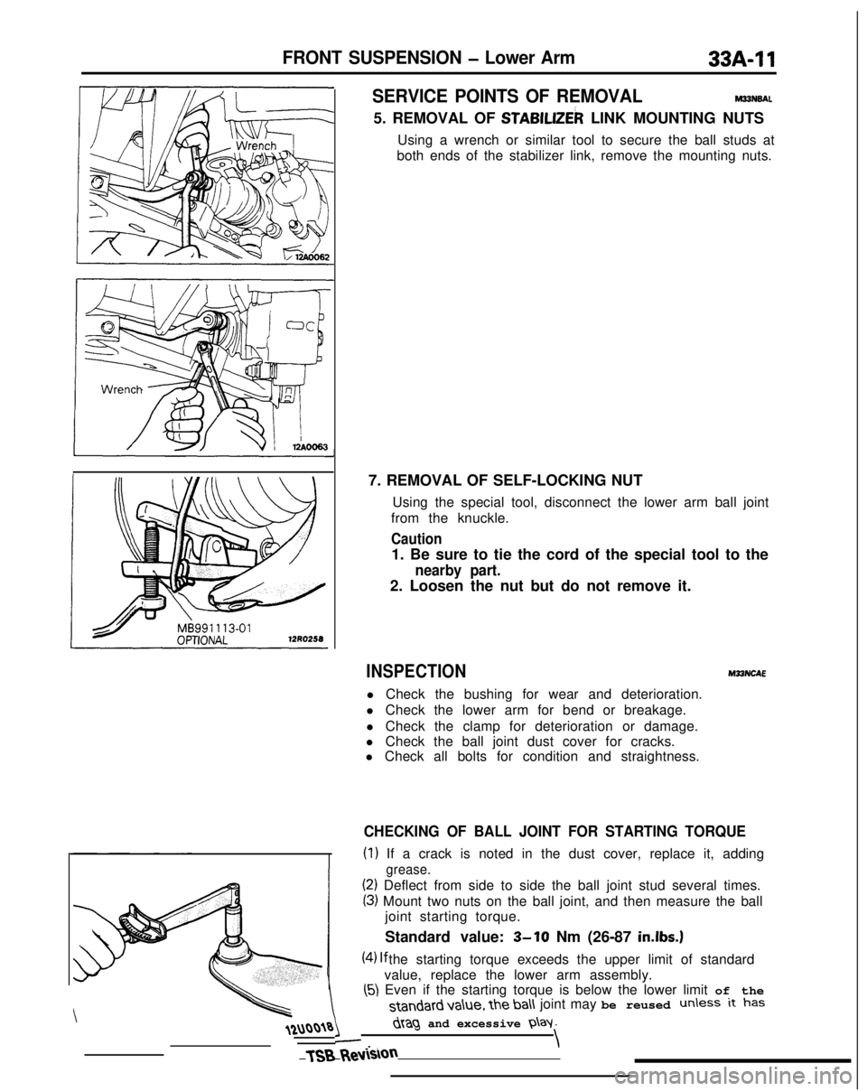
SERVICE POINTS OF REMOVALM33N6AL
5. REMOVAL OF STABlLlZEk LINK MOUNTING NUTS
Using a wrench or similar tool to secure the ball studs at
both ends of the stabilizer link, remove the mounting nuts.
7. REMOVAL OF SELF-LOCKING NUT Using the special tool, disconnect the lower arm ball joint
from the knuckle.
Caution
1. Be sure to tie the cord of the special tool to the
nearby part.
2. Loosen the nut but do not remove it.
INSPECTIONM33NCAE
l Check the bushing for wear and deterioration.
l Check the lower arm for bend or breakage.
l Check the clamp for deterioration or damage.
l Check the ball joint dust cover for cracks.
l Check all bolts for condition and straightness.
CHECKING OF BALL JOINT FOR STARTING TORQUE
(1) If a crack is noted in the dust cover, replace it, adding
grease.
(2) Deflect from side to side the ball joint stud several times.
(3) Mount two nuts on the ball joint, and then measure the ball
joint starting torque.
Standard value:
3-10 Nm (26-87 in.lbs.)
(4) lf the starting torque exceeds the upper limit of standard
value, replace the lower arm assembly.
(5) Even if the starting torque is below the lower limit of the standard va\ue,
the ba\\ joint may be reused unless it has
Page 933 of 1273
33/b12FRONT SUSPENSION - Lower Arm
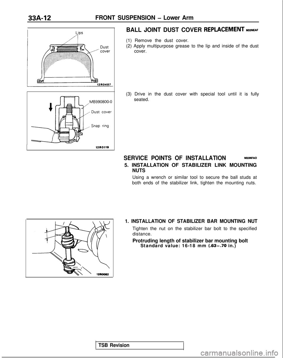
BALL JOINT DUST COVER
REPLACEMENTM~~NEAF
(1) Remove the dust cover.
(2) Apply multipurpose grease to the lip and inside of the dust cover.
(3) Drive in the dust cover with special tool until it is fully seated.
SERVICE POINTS OF INSTALLATIONM33NFAO
5. INSTALLATION OF STABILIZER LINK MOUNTING
NUTS
Using a wrench or similar tool to secure the ball studs at
both ends of the stabilizer link, tighten the mounting nuts.
TSB Revision 1. INSTALLATION OF STABILIZER BAR MOUNTING NUT
Tighten the nut on the stabilizer bar bolt to the specified
distance.
Protruding length of stabilizer bar mounting bolt Standard value: 16-18 mm
(.63-.70 in.)
Page 934 of 1273
FRONT SUSPENSION - Stabilizer Bar
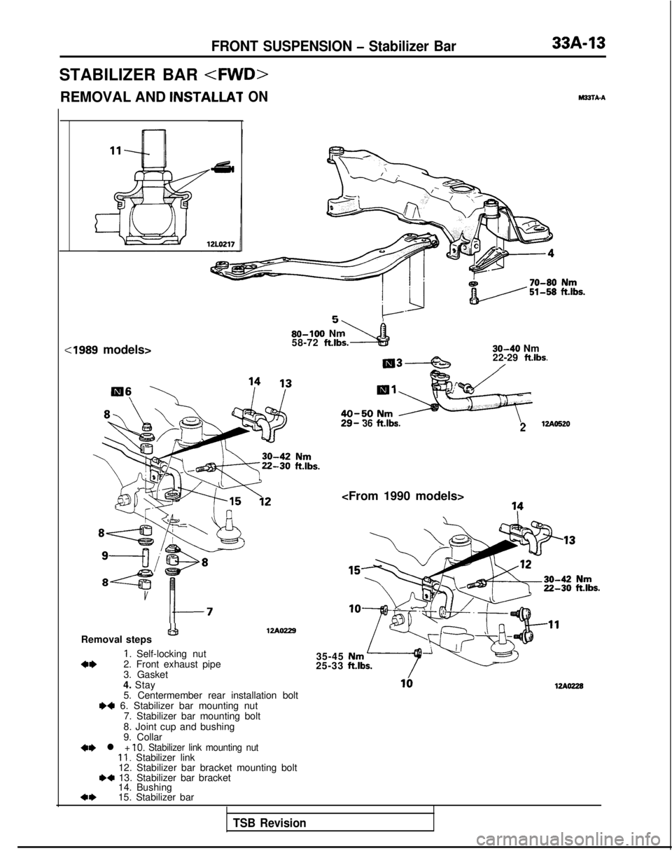
STABILIZER BAR
cl989 models>
P
80-100 Nm%?58-72 ft.lbs.30-40 Nm
22-29 ftlbs./
Removal steps&!I
1. Self-locking nuta*2. Front exhaust pipe
3. Gasket
29- 36ft.lbs.2
12Ao229
4. Stay 5. Centermember rear installation bolt
W 6. Stabilizer bar mounting nut 7. Stabilizer bar mounting bolt
8. Joint cup and bushing
9. Collar
+e l + 10. Stabilizer link mounting nut11. Stabilizer link
12. Stabilizer bar bracket mounting bolt
.+ 13. Stabilizer bar bracket 14. Bushing
*I)15. Stabilizer bar 35-45
25-33
UAW28
TSB Revision
Page 935 of 1273
33A-14
FRONT SUSPENSION - Stabilizer Bar
N-
;/fO’)/ --
Wire ’
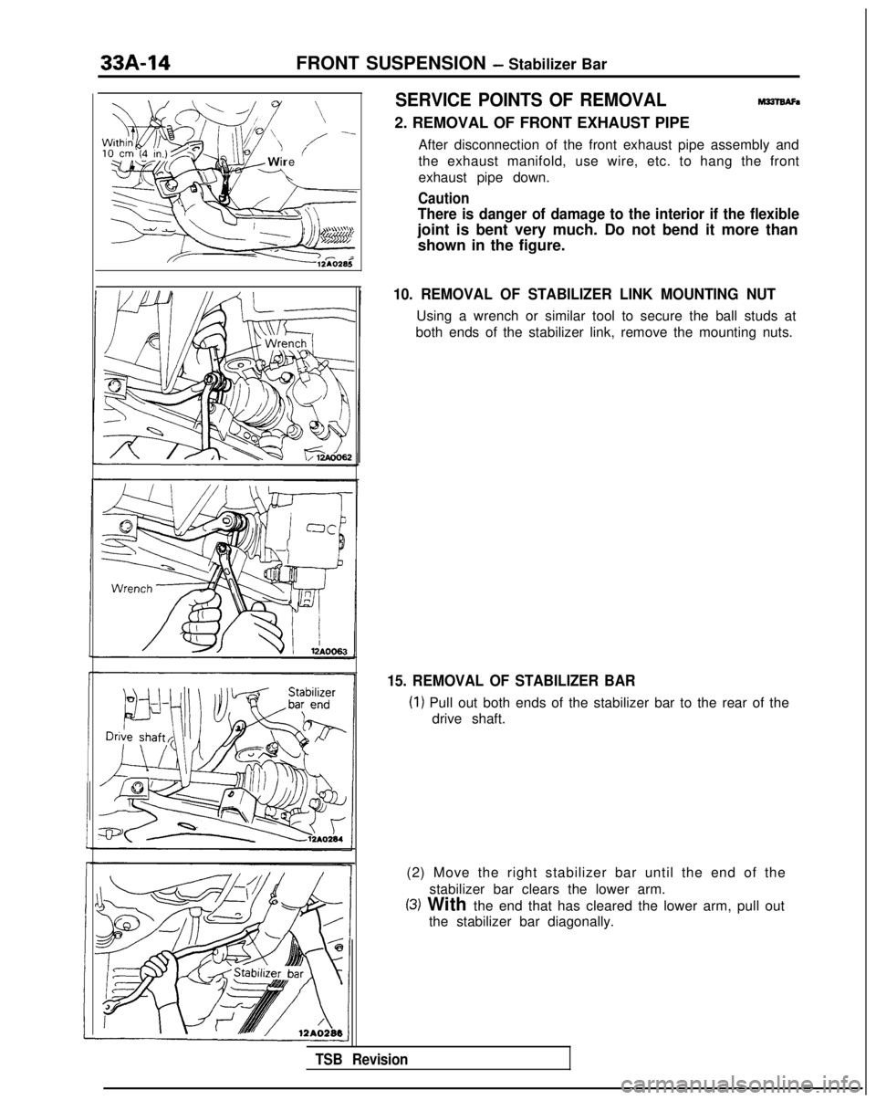
SERVICE POINTS OF REMOVALMalBAFa
2. REMOVAL OF FRONT EXHAUST PIPE
After disconnection of the front exhaust pipe assembly and
the exhaust manifold, use wire, etc. to hang the front
exhaust pipe down.
Caution
There is danger of damage to the interior if the flexible
joint is bent very much. Do not bend it more thanshown in the figure.
10. REMOVAL OF STABILIZER LINK MOUNTING NUT
Using a wrench or similar tool to secure the ball studs at
both ends of the stabilizer link, remove the mounting nuts.
15. REMOVAL OF STABILIZER BAR
(1) Pull out both ends of the stabilizer bar to the rear of the drive shaft.
(2) Move the right stabilizer bar until the end of the stabilizer bar clears the lower arm.
(3) With the end that has cleared the lower arm, pull outthe stabilizer bar diagonally.
TSB Revision
Page 936 of 1273
FRONT SUSPENSION - Stabilizer Bar 33A-15
12LO244
rpose
12LO217
lZLO242
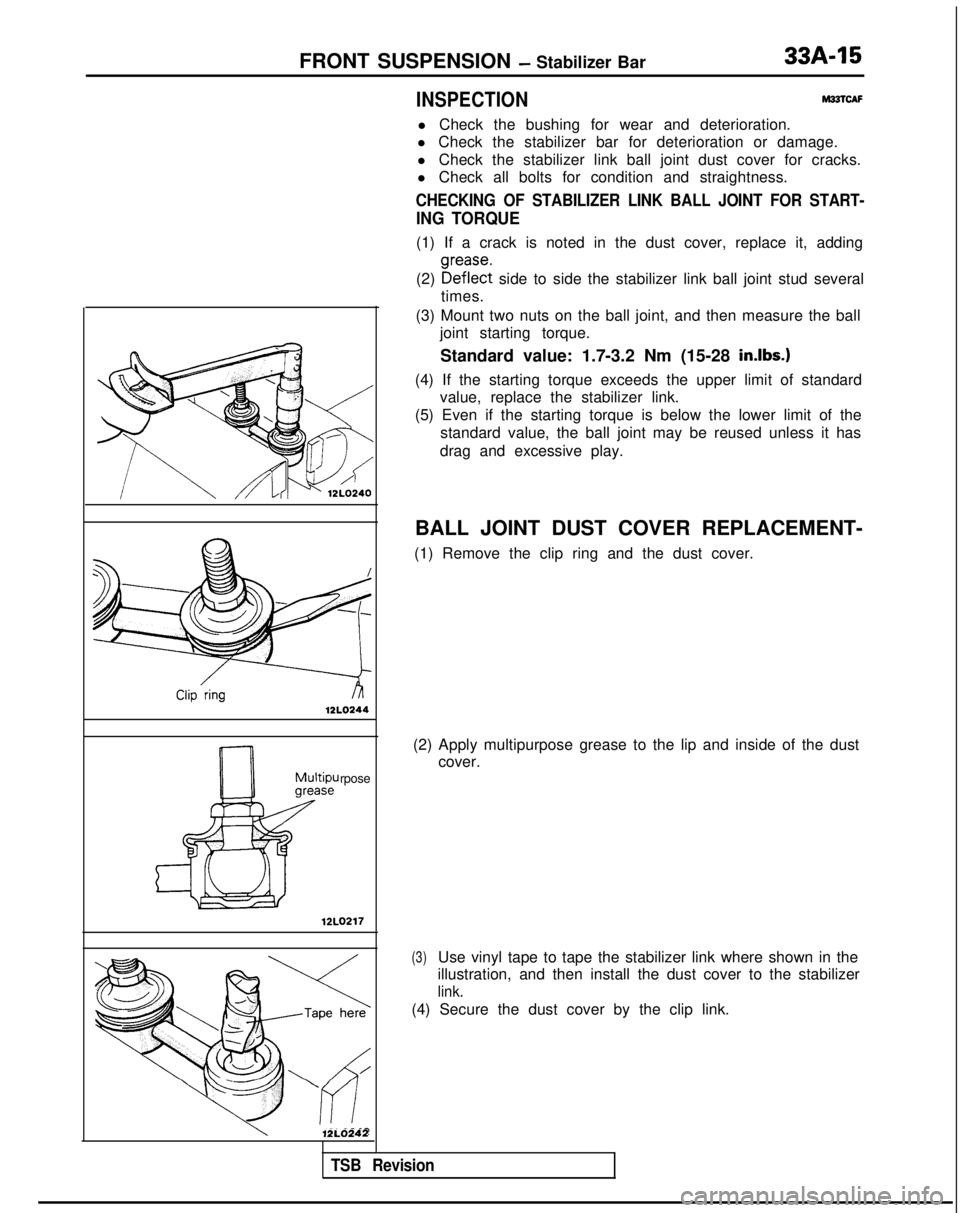
INSPECTIONM22lCAF
l Check the bushing for wear and deterioration.
l Check the stabilizer bar for deterioration or damage.
l Check the stabilizer link ball joint dust cover for cracks.
l Check all bolts for condition and straightness.
CHECKING OF STABILIZER LINK BALL JOINT FOR START-
ING TORQUE
(1) If a crack is noted in the dust cover, replace it, adding
(2)
!%% side to side the stabilizer link ball joint stud several
times.
(3) Mount two nuts on the ball joint, and then measure the ball joint starting torque.
Standard value: 1.7-3.2 Nm (15-28
in.lbs.1
(4) If the starting torque exceeds the upper limit of standard value, replace the stabilizer link.
(5) Even if the starting torque is below the lower limit of the standard value, the ball joint may be reused unless it has
drag and excessive play.
BALL JOINT DUST COVER REPLACEMENT-
(1) Remove the clip ring and the dust cover.
(2) Apply multipurpose grease to the lip and inside of the dust cover.
(3)Use vinyl tape to tape the stabilizer link where shown in the
illustration, and then install the dust cover to the stabilizer
link.
(4) Secure the dust cover by the clip link.
TSB Revision
Page 937 of 1273
33A-16FRONT SUSPENSION - Stabilizer Bar
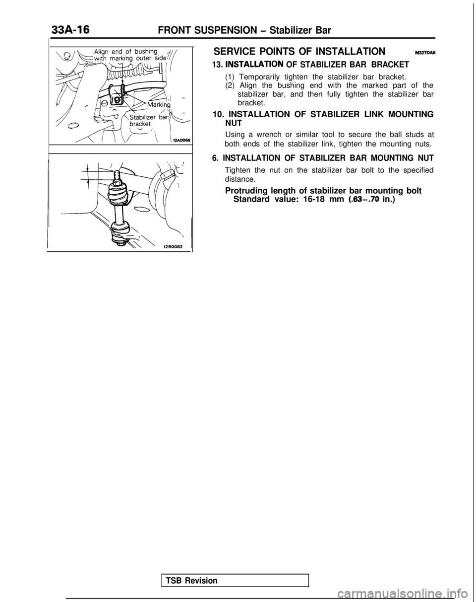
SERVICE POINTS OF INSTALLATION
M33TDAK
13. INSTALLATlON OF STABILIZER BAR BRACKET
(1) Temporarily tighten the stabilizer bar bracket.
(2) Align the bushing end with the marked part of the
stabilizer bar, and then fully tighten the stabilizer bar
bracket.
10. INSTALLATION OF STABILIZER LINK MOUNTING
NUT
Using a wrench or similar tool to secure the ball studs at
both ends of the stabilizer link, tighten the mounting nuts.
6. INSTALLATION OF STABILIZER BAR MOUNTING NUT
Tighten the nut on the stabilizer bar bolt to the specified distance.
Protruding length of stabilizer bar mounting bolt Standard value: 16-18 mm (.63-.70
in.)
TSB Revision
Page 938 of 1273
FRONT SUSPENSION - Stabilizer Bar
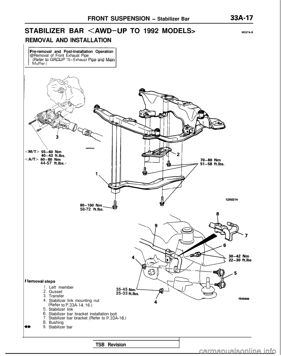
STABILIZER BAR
REMOVAL AND INSTALLATION
Pre-removal and Post-installation Operation@Removal of Front Exhaust Pipe(Refer to GROUP 15-Exhaust Pipe and Main
\:M/T> 55-60 Nm40-43 ftlbs.
:A/T>
60-80 Nm44-57 ft.lbs. *
Iemoval steps
::3.4.
::
i:9.
Left member
Gusset
Transfer
Stabilizer link mounting nut
(Refer to P.33A-14, 16.)
Stabilizer link
Stabilizer bar bracket installation
Stabilizer bar bracket (Refer to
PBushing
Stabilizer bar 80-100
Nm58-72 ftlbs.
35-45
25-33
bolt
.33A-16.)
70-80 Nm51-58 ftlbs. MBJTA-B
-42
Nmiik.30 ft.lbs
TSB Revision
Page 939 of 1273
33A-18FRONT SUSPENSION - Stabilizer Bar
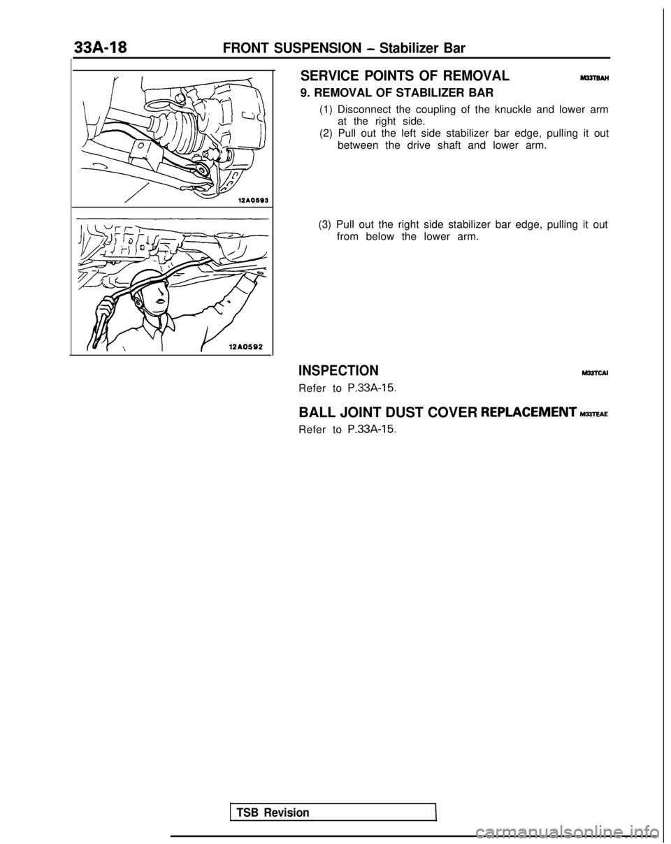
SERVICE POINTS OF REMOVAL
9. REMOVAL OF STABILIZER BAR (1) Disconnect the coupling of the knuckle and lower armat the right side.
(2) Pull out the left side stabilizer bar edge, pulling it out between the drive shaft and lower arm.
(3) Pull out the right side stabilizer bar edge, pulling it out from below the lower arm.
INSPECTION
Refer to P.33A-15.
hl33lcAI
BALL JOINT DUST COVER REPLACEMENTM~E
Refer to P.33A-15.
TSB Revision
Page 940 of 1273
339-l
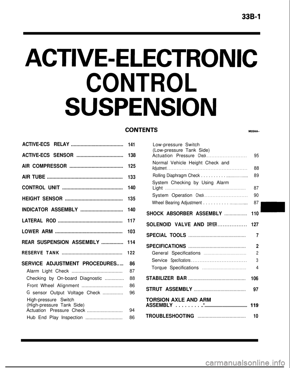
ACTIVE-ELECTRONIC
CONTROL
SUSPENSION
ACTIVE-ECS RELAY......................................141
ACTIVE-ECSSENSOR.................................. 138
AIRCOMPRESSOR.......................................125
AIR TUBE.......................................................133
CONTROLUNIT............................................ 140
HEIGHT SENSOR ..........................................
135
INDICATORASSEMBLY............................... 140
LATERALROD...............................................117
LOWER
ARM.................................................103
REAR
SUSPENSION ASSEMBLY................114
RESERVETANK............................................ 122
SERVICE ADJUSTMENT PROCEDURES.....86
Alarm Light Check.....................................87
Checking by On-board Diagnostic ..............88
FrontWheelAlignment .............................. 86
G sensor Output Voltage Check ...............96
High-pressure Switch
(High-pressure Tank Side)
Actuation Pressure Check
.......................... 94
Hub End Play Inspection ...........................86 M33AA-
Low-pressure Switch
(Low-pressure Tank Side)
Actuation
PressureCheck . . . . . . . . . . . . . . . . . . . . . . . . .95
Normal Vehicle Height Check and
Adjustment . . . . . . . . . . . . . . . . . . . . . . . . . . . . . . .\
. . . . . . . . . . . . . . . . . . .88
Rolling Diaphragm Check . . . . . . . . . . .._.............. 89
System Checking by Using Alarm
Light
. . . . . . . . . . . . . . . . . . . . . . . . . . . . . . . . . . . . \
. . . . . . . . . . . . . . . . . . . . . . . .87
System OperationCheck . . . . . . . . . . . . . . . . . . . . . . . . . . .90
Wheel Bearing Adjustment . . . . . . . . . .
.._........... 87
SHOCKABSORBER ASSEMBLY. . . . . . . . . . . . . . . . .110
SOLENOIDVALVEANDDRYER . . . . . . . . . . . . . . . . .127
SPECIAL TOOLS. . . . . . . . . . . . . . . . . . . . . . . . . . . . . . . . . . . . \
. . . . . . .7
SPECIFICATIONS. . . . . . . . . . . . . . . . . . . . . . . . . . . . . . . . . . . . \
. . . . . . .2
GeneralSpecifications. . . . . . . . . . . . . . . . . . . . . . . . . . . . . . . .2
ServiceSpecifications . . . . . . . . . . . . . . . . . . . . . . . . . . . . .\
. . . .3
TorqueSpecifications. . . . . . . . . . . . . . . . . . . . . . . . . . . . . . . . .4
STABILIZER BAR. . . . . . . . . . . . . . . . . . . . . . . . . . . . . . . . . . . . \
. . . . . . .106
STRUT ASSEMBLY. . . . . . . . . . . . . . . . . . . . . . . . . . . . . . . . . . . . \
. . .97
TORSION AXLE AND ARM
ASSEMBLY. . . . . . . . ..*.........................................119,
TROUBLESHOOTING. . . . . . . . . . . . . . . . . . . . . . . . . . . . . . . . . . . .10