MITSUBISHI GALANT 1989 Service Repair Manual
Manufacturer: MITSUBISHI, Model Year: 1989, Model line: GALANT, Model: MITSUBISHI GALANT 1989Pages: 1273, PDF Size: 37.62 MB
Page 941 of 1273
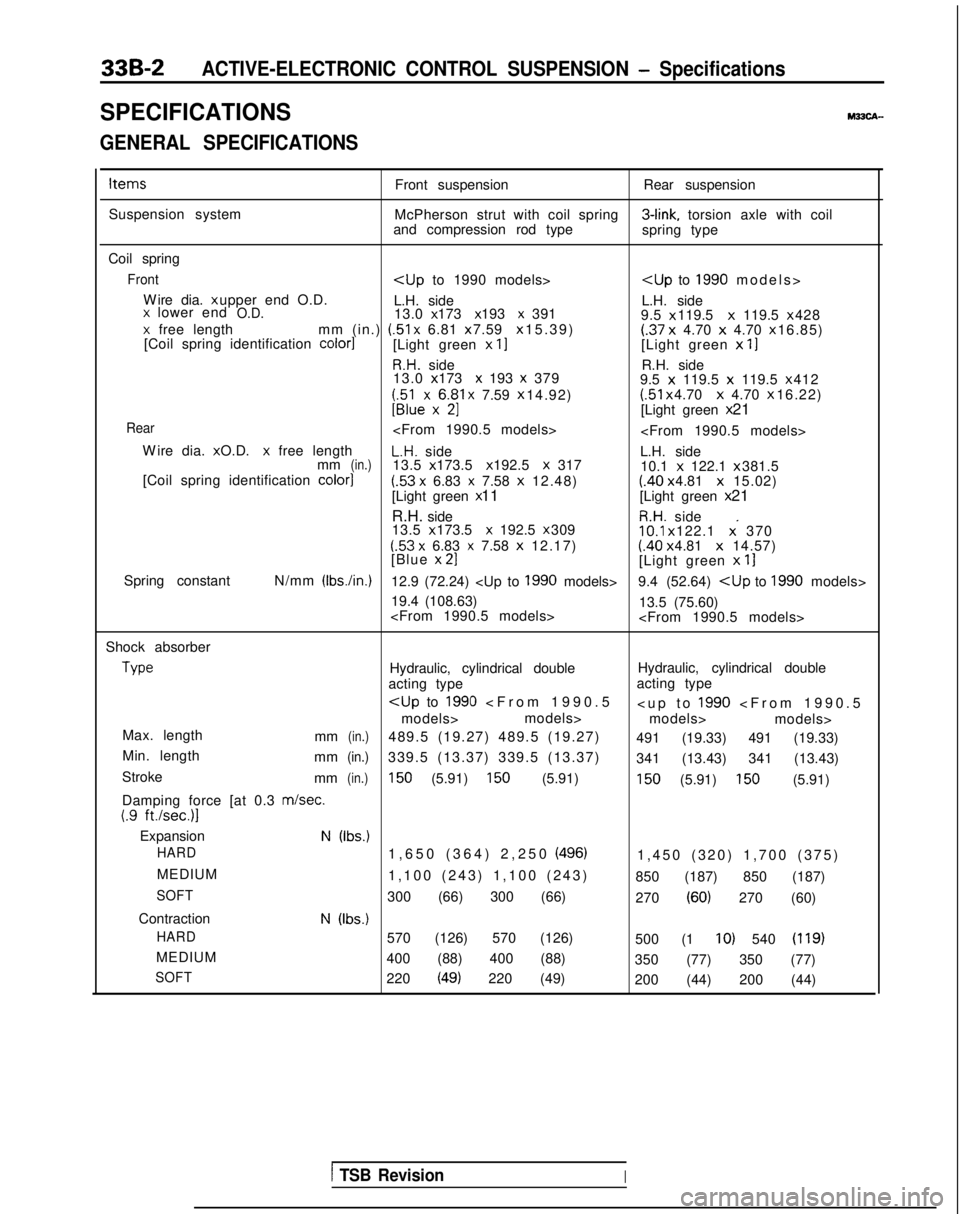
33B-2ACTIVE-ELECTRONIC CONTROL SUSPENSION - Specifications
SPECIFICATIONSM33CA-
GENERAL SPECIFICATIONS
ItemsFront suspensionRear suspension
Suspension system McPherson strut with coil spring 3-link,
torsion axle with coil
and compression rod type spring type
Coil spring
Front
Wire dia. x upper end O.D.
L.H. side L.H. side
x lower endO.D.13.0 x 173 x 193 x 391
9.5 x 119.5 x
119.5 x 428x free length
mm (in.) (51
x 6.81 x 7.59 x 15.39)(.37
x
4.70 x 4.70 x 16.85)
[Coil spring identification color1[Light green x II[Light green x
11
R.H. side R.H. side
13.0 x 173 x 193 x 379
9.5 x
119.5 x
119.5 x 412
;;lexx6$1 x 7.59
x 14.92) (51
x 4.70 x
4.70 x 16.22)U[Light green
x 21
Rear
W
ire dia. x O.D.
x free lengthL.H. side
L.H. side
mm(in.)13.5 x 173.5 x 192.5 X 317
10.1 x
122.1 x 381.5
[Coil spring identification color]
(.53 x 6.83 x 7.58
x
12.48)(.40 x 4.81 x
15.02)
[Light green x 11
[Light green x 21
R.H. side
R.H. side
13.5 x 173.5 x 192.5 x 30910.1
x 122.1 x. 370(53 x 6.83 x 7.58
x
12.17)(.40 x 4.81 x
14.57)
[Blue x 21[Light green
x
11
Spring constant N/mm (Ibs./in.)12.9 (72.24)
19.4 (108.63) 13.5 (75.60)
Shock absorber Type
Hydraulic, cylindrical double
Hydraulic, cylindrical double
acting type acting type
models> models>
models> models>
Max. length mm
(in.)489.5 (19.27) 489.5 (19.27) 491 (19.33) 491 (19.33)
Min. length mm
(in.)339.5 (13.37) 339.5 (13.37) 341 (13.43) 341 (13.43)
Stroke mm
(in.)150 (5.91) 150 (5.91)150 (5.91) 150 (5.91)
Damping force [at 0.3
m/set.(.9 ft./sec.)l
ExpansionN (Ibs.)
HARD
1,650 (364) 2,250 (496)1,450 (320) 1,700 (375
)
MEDIUM 1,100 (243) 1,100 (243) 850 (187) 850 (187)
SOFT300 (66) 300 (66) 270 (60) 270 (60)
Contraction
N (Ibs.)
HARD
570 (126) 570 (126) 500 (1 IO) 540 (119)
MEDIUM400 (88) 400 (88) 350 (77) 350 (77)
SOFT220 (49) 220 (49)200 (44) 200 (44)
1 TSB RevisionI
Page 942 of 1273
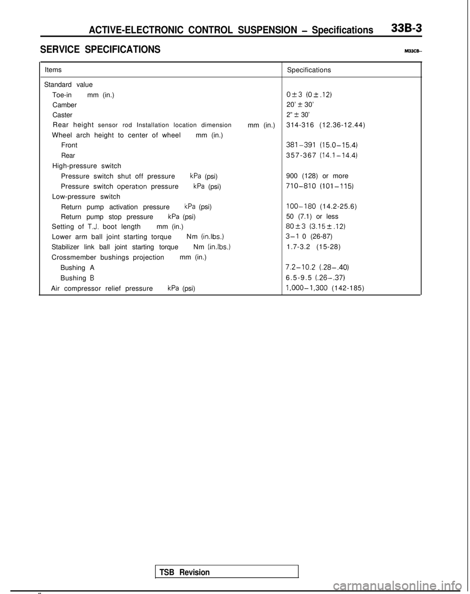
ACTIVE-ELECTRONIC CONTROL SUSPENSION - Specifications33B-3
SERVICE SPECIFICATIONSM33cE-
ItemsSpecifications
Standard value Toe-in mm (in.)
O&3 (O-t.12)
Camber 20’ t 30’
Caster
2” t 30’
Rear height sensor rod Installation location dimension
mm (in.)314-316 (12.36-12.44)
Wheel arch height to center of wheel mm (in.)
Front
381-391 (15.0-15.4)
Rear357-367 (14.1-14.4)
High-pressure switch
Pressure switch shut off pressure
kPa (psi) 900 (128) or more
Pressure switch operatton
pressure
kPa (psi)710-810 (101-115)
Low-pressure switch
Return pump activation pressure
kPa (psi)100-180 (14.2-25.6)
Return pump stop pressure
kPa (psi) 50 (7.1) or less
Setting of
T.J. boot length mm (in.)80+3 (3.152.12)
Lower arm ball joint starting torque Nm (inlbs.)3-l 0 (26-87)
Stabilizer link ball joint starting torque Nm (in.lbs.)
1.7-3.2 (15-28)
Crossmember bushings projection mm (in.)
Bushing A
7.2-10.2 (.28-.40)
Bushing B6.5-9.5 (.26-.37)
Air compressor relief pressurekPa (psi) l,OOO-1,300
(142-185)
TSB Revision
Page 943 of 1273
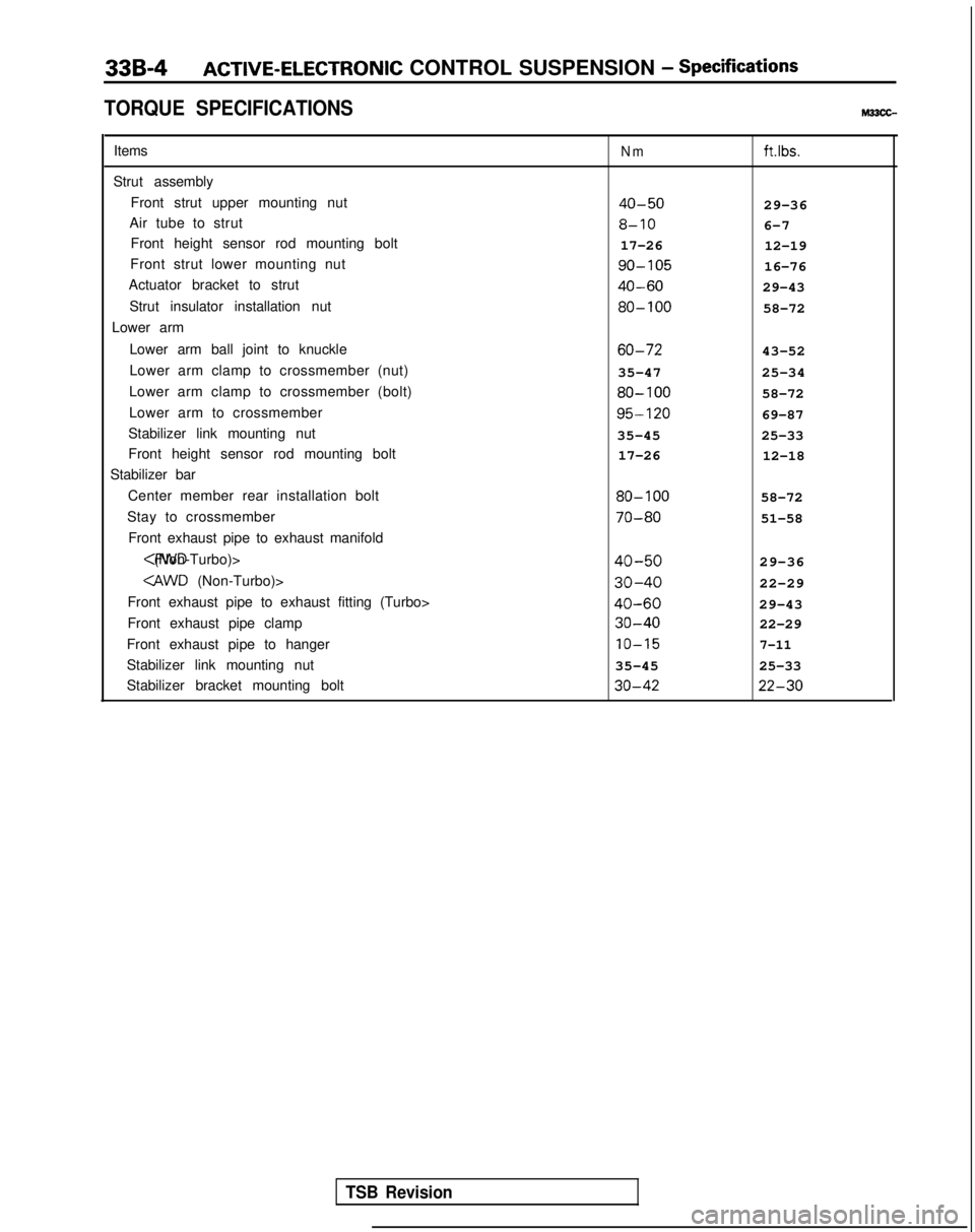
33B-4ACTIVE-ELECTRONIC CONTROL SUSPENSION - Specifications
TORQUE SPECIFICATIONS
Items
Strut assembly Front strut upper mounting nut
Air tube to strut Front height sensor rod mounting bolt
Front strut lower mounting nut
Actuator bracket to strut
Strut insulator installation nut
Lower arm
Lower arm ball joint to knuckle
Lower arm clamp to crossmember (nut)
Lower arm clamp to crossmember (bolt)
Lower arm to crossmember
Stabilizer link mounting nut
Front height sensor rod mounting bolt
Stabilizer bar
Center member rear installation bolt
Stay to crossmember Front exhaust pipe to exhaust manifold
Front exhaust pipe to exhaust fitting (Turbo>
Front exhaust pipe clamp
Front exhaust pipe to hanger
Stabilizer link mounting nut
Stabilizer bracket mounting boltNmftlbs.
40-5029-36
8-106-7
17-26 12-19 go-105
16-76
40-6029-43 80-100
58-72 60-72
43-52
35-47 25-34 80-100
58-72 95-120
69-87
35-45 25-33
17-26 12-18 80-100
58-72 70-80
51-58
40-5029-36
30-4022-29
40-6029-43 30-40
22-29 IO-15
7-11
35-45
25-33 30-42 22-30
TSB Revision
Page 944 of 1273
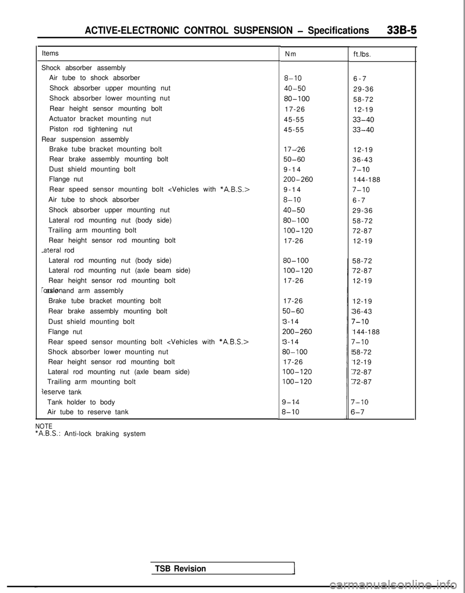
ACTIVE-ELECTRONIC CONTROL SUSPENSION - Specifications33B-5
ItemsNmft.lbs.
Shock absorber assemblyAir tube to shock absorber
Shock absorber upper mounting nut
Shock absorber lower mounting nut
Rear height sensor mounting bolt
Actuator bracket mounting nut
Piston rod tightening nut
Rear suspension assembly Brake tube bracket mounting bolt
Rear brake assembly mounting bolt
Dust shield mounting bolt
Flange nut
8-106-
7
40-5029-36
80-10058-72
17-26 12-19
45-55
33-40
45-5533-40
Rear speed sensor mounting bolt
Air tube to shock absorber
Shock absorber upper mounting nut
Lateral rod mounting nut (body side)
Trailing arm mounting bolt
Rear height sensor rod mounting bolt -ateral
rod 17~26
12-19
50-6036-43
9-1
4
7-10
200-260144-188
9-1
4
7-10
8-106-
7
40-5029-36
80-10058-72
100-12072-87
17-26 12-19
Lateral rod mounting nut (body side)
Lateral rod mounting nut (axle beam side)
Rear height sensor rod mounting bolt rorsion axle and arm assembly
Brake tube bracket mounting bolt
Rear brake assembly mounting bolt
Dust shield mounting bolt
Flange nut
80-100
100-120
17-26 58-72
72-87
12-19
Rear speed sensor mounting bolt
Shock absorber lower mounting nut Rear height sensor rod mounting bolt
Lateral rod mounting nut (axle beam side)
Trailing arm mounting bolt
deserve tank 17-26
50-60
3-14
200-260
3-14
30- 100
17-26
100-120
100-120
12-19
36-43
7-10
144-188
7-10
58-72
12-19
72-87
72-87
Tank holder to body
Air tube to reserve tank
7-10
s-7
TSB Revision
NOTE “A.B.S.:
Anti-lock braking system
Page 945 of 1273
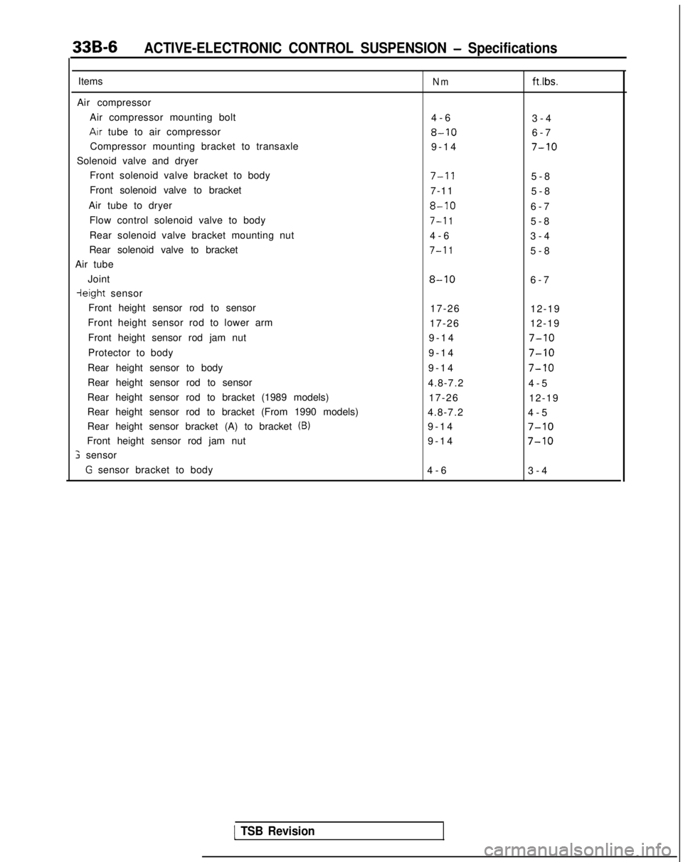
33B-6ACTIVE-ELECTRONIC CONTROL SUSPENSION - Specifications
Items
Air compressor Air compressor mounting bolt
Arr tube to air compressor
Compressor mounting bracket to transaxle
Solenoid valve and dryer Front solenoid valve bracket to body
Front solenoid valve to bracket
Air tube to dryer Flow control solenoid valve to body
Rear solenoid valve bracket mounting nut
Rear solenoid valve to bracket
Air tube
Joint
ieight sensor
Front height sensor rod to sensor
Front height sensor rod to lower arm
Front height sensor rod jam nut
Protector to body
Rear height sensor to body
Rear height sensor rod to sensor
Rear height sensor rod to bracket (1989 models)
Rear height sensor rod to bracket (From 1990 models)
Rear height sensor bracket (A) to bracket
(B)
Front height sensor rod jam nut
; sensor
G sensor bracket to body
Nmftlbs.
4-
6
3-4
8-106-
7
9-14
7-10
7-l 15-
8
7-11 5-8
8-106-
7
7-l 15-
8
4-6 3-4
7-l 15-
8
8-106-
7
17-26 12-19
17-26 12-19
9-14
7-10
9-1
4
7-10
9-1
4
7-10
4.8-7.2
4-
5
17-26 12-19
4.8-7.2 4-5
9-14
7-10
9-1
4
7-10
4-
6
3-4
1 TSB Revision
Page 946 of 1273
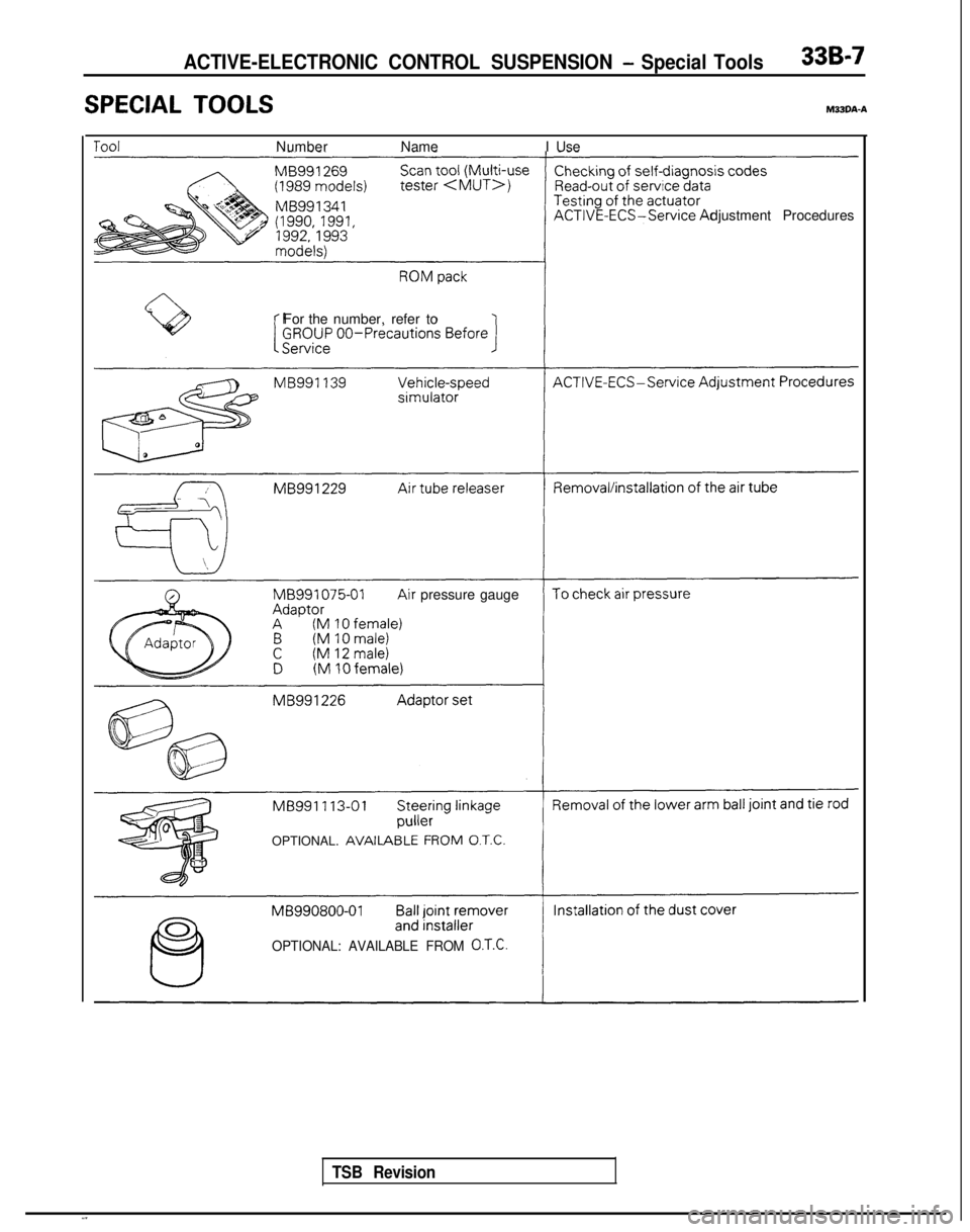
ACTIVE-ELECTRONIC CONTROL SUSPENSION - Special Tools336-7
SPECIAL TOOLSM33DA-A
NumberName I Use
djustment Procedures
For the number, refer to
tr pressure gauge
OPTIONAL.
AVAILA
OPTIONAL: AVAILABLE FROM O.T.C.
TSB Revision
Page 947 of 1273
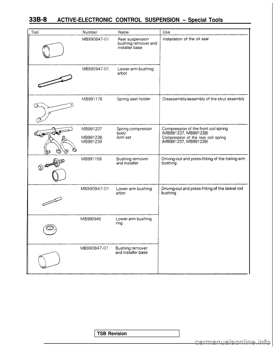
33B-8ACTIVE-ELECTRONIC CONTROL SUSPENSION - Special Tools
ToolNumberNameI Use (MB991237,
MB9912381Compression of the rear coil spring (MB991237,
MB9912391
TSB Revision
Page 948 of 1273

33B-9
NOTES
Page 949 of 1273
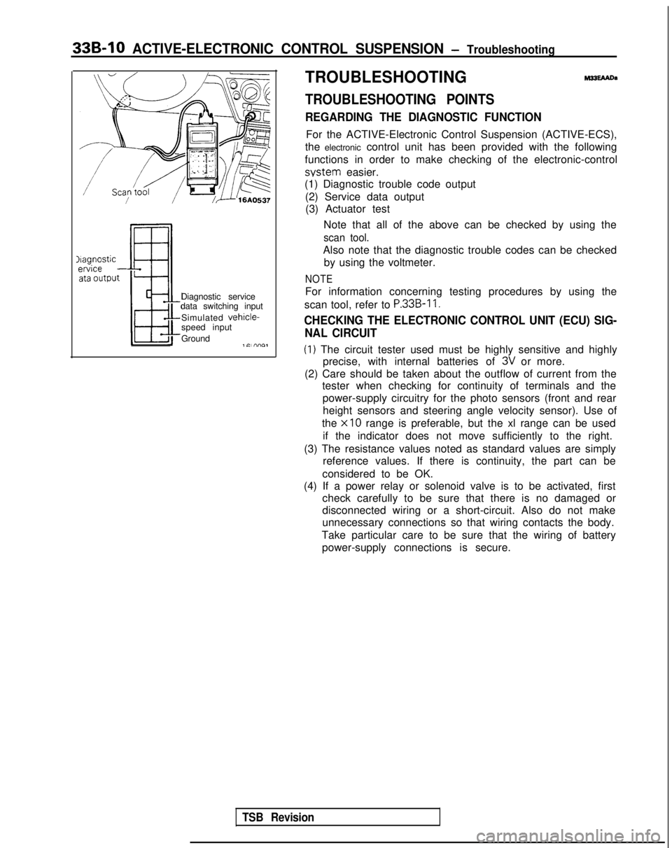
33B-10 ACTIVE-ELECTRONIC CONTROL SUSPENSION - Troubleshooting
Ifagnosticervice
- ata 0utDut
Diagnostic service
data switching input
Simulated
vehicle-speed input
Ground
1 Cl nno,
TROUBLESHOOTINGhw3EAAtm
TROUBLESHOOTING POINTS
REGARDING THE DIAGNOSTIC FUNCTION
For the ACTIVE-Electronic Control Suspension (ACTIVE-ECS),
the electronic control unit has been provided with the following
functions in order to make checking of the electronic-control system
easier.
(1) Diagnostic trouble code output
(2) Service data output(3) Actuator test
Note that all of the above can be checked by using the
scan tool.
Also note that the diagnostic trouble codes can be checkedby using the voltmeter.
NOTE
For information concerning testing procedures by using the
scan tool, refer to
P.33B-11.
CHECKING THE ELECTRONIC CONTROL UNIT (ECU) SIG- NAL CIRCUIT
(1) The circuit tester used must be highly sensitive and highly precise, with internal batteries of
3V or more.
(2) Care should be taken about the outflow of current from the tester when checking for continuity of terminals and the
power-supply circuitry for the photo sensors (front and rearheight sensors and steering angle velocity sensor). Use of
the
x10 range is preferable, but the xl range can be used
if the indicator does not move sufficiently to the right.
(3) The resistance values noted as standard values are simply reference values. If there is continuity, the part can be
considered to be OK.
(4) If a power relay or solenoid valve is to be activated, first check carefully to be sure that there is no damaged or
disconnected wiring or a short-circuit. Also do not make
unnecessary connections so that wiring contacts the body.
Take particular care to be sure that the wiring of battery power-supply connections is secure.
TSB Revision
Page 950 of 1273
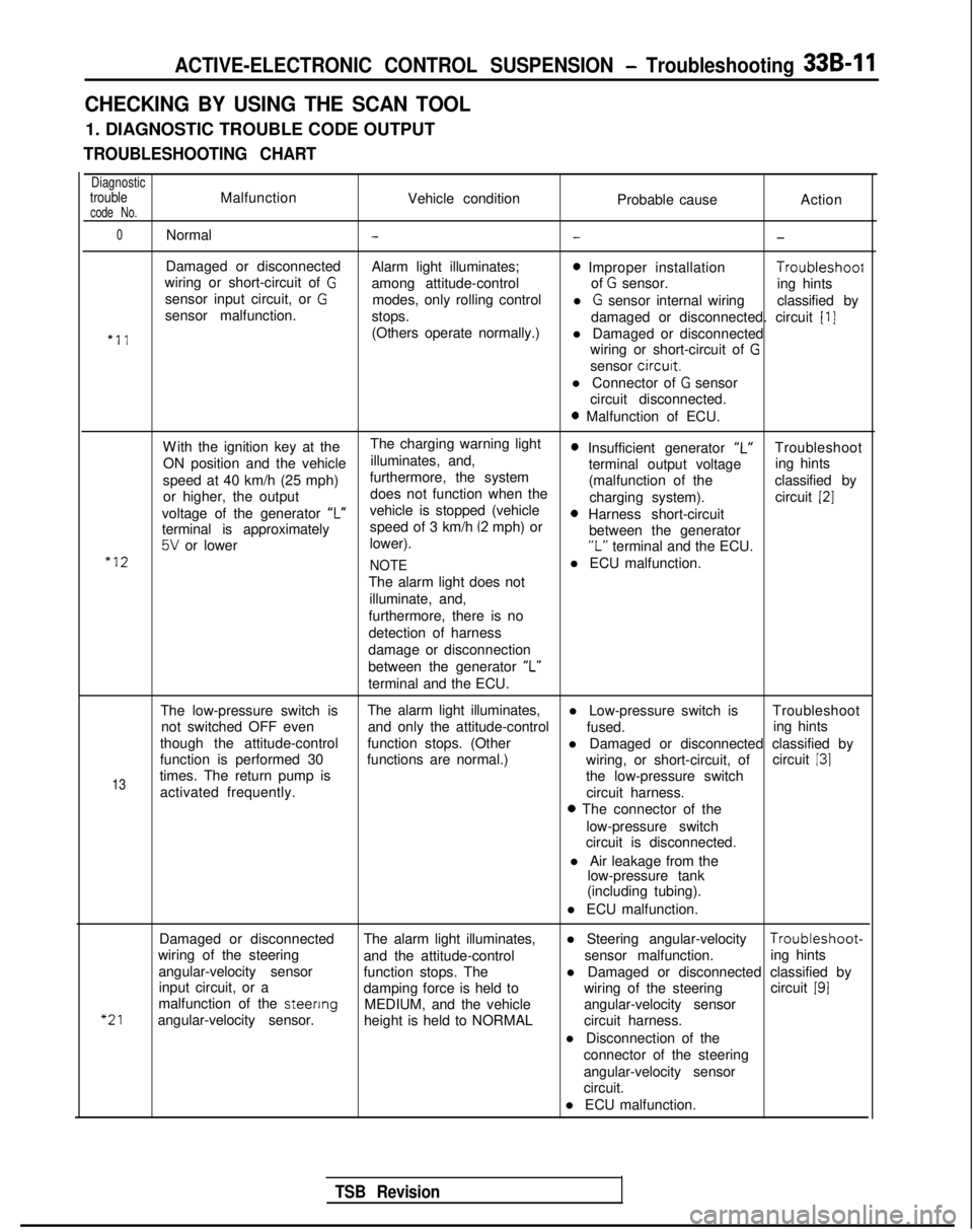
ACTIVE-ELECTRONIC CONTROL SUSPENSION - Troubleshooting 33B-11
CHECKING BY USING THE SCAN TOOL
1. DIAGNOSTIC TROUBLE CODE OUTPUT
TROUBLESHOOTING CHART
DiagnostictroubleMalfunctionVehicle conditioncode No.Probable causeAction
0Normal---
Damaged or disconnected
Alarm light illuminates;0 Improper installation Troubleshoof
wiring or short-circuit of Gamong attitude-control of G sensor.
sensor input circuit, or Ging hints
modes, only rolling control
sensor malfunction. l
G sensor internal wiring
classified by
stops. damaged or disconnected. circuit
[I]
“11(Others operate normally.)l Damaged or disconnected
wiring or short-circuit of
G
sensor circurt.
l Connector of
G sensor
circuit disconnected.
0 Malfunction of ECU.
W
ith the ignition key at the
The charging warning light
ON position and the vehicle illuminates, and,
0 Insufficient generator “L”Troubleshoot
speed at 40 km/h (25 mph) furthermore, the system terminal output voltage
ing hints
or higher, the output does not function when the (malfunction of the
classified by
charging system). circuit
[2]
voltage of the generator ‘I”vehicle is stopped (vehicle0 Harness short-circuit
terminal is approximately speed of 3 km/h (2 mph) or
5V or lower
lower). between the generator“L” terminal and the ECU.“12
NOTEl ECU malfunction.
The alarm light does not illuminate, and,
furthermore, there is no
detection of harness
damage or disconnection
between the generator “L”
terminal and the ECU.
The low-pressure switch is The alarm light illuminates,
l Low-pressure switch is Troubleshoot
not switched OFF even and only the attitude-control
fused.
though the attitude-control ing hints
function stops. (Other l Damaged or disconnected classified by
function is performed 30 functions are normal.) circuit
131
13times. The return pump is wiring, or short-circuit, of
the low-pressure switch
activated frequently. circuit harness.
0 The connector of the
low-pressure switch
circuit is disconnected.
l Air leakage from the low-pressure tank
(including tubing).
l ECU malfunction.
“21
Damaged or disconnected The alarm light illuminates,l Steering angular-velocity Troubleshoot-
wiring of the steering and the attitude-control sensor malfunction.
angular-velocity sensor ing hints
function stops. The
input circuit, or a l Damaged or disconnected classified by
damping force is held to wiring of the steeringcircuit
191malfunction of the steenng
MEDIUM, and the vehicle
angular-velocity sensor. angular-velocity sensor
height is held to NORMAL circuit harness.
l Disconnection of the connector of the steering
angular-velocity sensor
circuit.
l ECU malfunction.
TSB Revision