MITSUBISHI GALANT 1989 Service Repair Manual
Manufacturer: MITSUBISHI, Model Year: 1989, Model line: GALANT, Model: MITSUBISHI GALANT 1989Pages: 1273, PDF Size: 37.62 MB
Page 951 of 1273
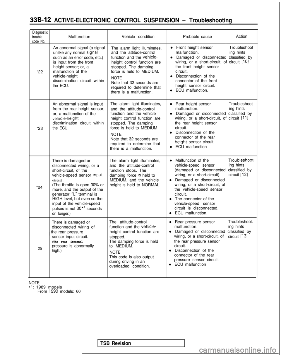
33B-12 ACTIVE-ELECTRONIC CONTROL SUSPENSION - Troubleshooting
Diagnostic
troubleMalfunction Vehicle condition
Probable causeAction
code No.
An abnormal signal (a signal
The alarm light illuminates, l Front height sensor
Troubleshoot
unlike any normal
srgnaland the attitude-control malfunction.
ing hints
such as an error code, etc.) function and the
vehicle-l Damaged or disconnected classified by
is input from the front height control function are wiring, or a short-circuit, of circuit [IO]
height sensor; or, a stopped. The damping the front height sensor
“22 malfunction of the
force is held to MEDIUM. circuit.
vehicle-height
NOTEl Disconnection of the
discrimination circuit within
the ECU.Note that 32 seconds are connector of the front
required to determine that height sensor circuit.
there is a malfunction. l ECU malfunction.
“23 An abnormal signal is input
The alarm light illuminates,
l Rear height sensorTroubleshoot
from the rear height sensor; and the attitude-control malfunction.
ing hints
or, a malfunction of the function and the vehicle
l Damaged or disconnected classified byvehicle-height
height control function are
wiring, or a short-circuit, of circuit
[I 11
discrimination circuit within
stopped. The damping the rear height sensor
the ECU.force is held to MEDIUM circuit.
NOTEl Disconnection of the
Note that 32 seconds are connector of the rear
required to determine that
height sensor circuit.
there is a malfunction. l ECU malfunction
There is damaged or The alarm light illuminates, l Malfunction of the Troubleshoot-
disconnected wiring, or a and the attitude-control vehicle-speed sensor
ing hints
short-circuit, of the function stops. The (damaged or disconnected classified by
vehicle-speed sensor Input
damping force
IS held to wiring, or a short-circuit).
circuit [ 121
circuit.MEDIUM, and the vehicle l Damaged or disconnected
“24 (The throttle is open 30% or
height is held to NORMAL. wiring, or a short-circuit, of
more, and the output of the the vehicle-speed sensor
generator “L”
terminal is circuit.
HIGH level, but even so the l The connector of the
input of the vehicle-speed vehicle-speed sensor
pulses is not
30*’ seconds circuit is disconnected.
or longer.)l ECU malfunction.
There is damaged or The attitude-control
l Rear pressure sensorTroubleshoot.
disconnected wiring of function and the
vehicle-malfunction.
ing hints
/ the rear pressure height control function arel Damaged or disconnected classified by
sensor input circuit. stopped. wiring, or a short-circuit, of
circuit
[I31
(The rear internalThe damping force is held the rear pressure sensor
25pressure is abnormally
to MEDIUM. circuit.
high.)
NOTEl Disconnection of the
This code is also output connector of the rear
during driving in an pressure sensor circuit.
overloaded condition. l ECU malfunction
NOTE+1: 1989 models
From 1990 models: 60
TSB Revision
Page 952 of 1273
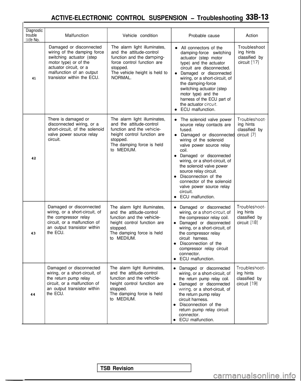
ACTIVE-ELECTRONIC CONTROL SUSPENSION - Troubleshooting 33B-13
Diagnostic
trouble
zode No.MalfunctionVehicle condition Probable causeAction
Damaged or disconnected The alarm light illuminates,
l All connectors of theTroubleshoot
wiring of the damping force and the attitude-control
damping-force switchinging hints
switching actuator (step function and the damping-
actuator (step motor classified by
motor type) or of the force control function are
type) and the actuatorcircuit
[ 171
actuator circuit, or a
stopped.
circuit are disconnected.
malfunction of an output The vehicle height is held to
l Damaged or disconnected41transistor within the ECU. NORMAL.
wiring, or a short-circuit, of
the damping-force
switching actuator (step
motor type) and the
harness of the ECU part of
the actuator circutt.
l ECU malfunction.
There is damaged or The alarm light illuminates,
l The solenoid valve power Troubleshoot-
disconnected wiring, or a and the attitude-control
short-circuit, of the solenoid source relay contacts are
ing hints
function and the
vehicle-fused. classified by
valve power source relay height control function are
circuit. l Damaged or disconnected circuit
(71stopped.
wiring of the solenoid
The damping force is held valve power source relay
to MEDIUM. coil.
42
l Damaged or disconnected
wiring, or a short-circuit, of
the solenoid valve power source relay circuit.
l Disconnection of the connector of the solenoid
valve power source relay
circuit.
l ECU malfunction.
Damaged or disconnected The alarm light illuminates,
l Damaged or disconnected Troubleshoot-
wiring, or a short-circuit, of and the attitude-control wiring, or a
short-circuit, ofing hints
the compressor relay function and the
vehicle-the compressor relay coil.classified by
circuit, or a malfunction of height control function are
l Damaged or disconnectedcircuit [I81an output transistor within
stopped.
43
the ECU.wiring, or a short-circuit, of
The damping force is held the compressor relay
to MEDIUM.
circuit harness.
l Disconnection of the
compressor relay circuit
connector.
l ECU malfunction.
Damaged or disconnected The alarm light illuminates,
l Damaged or disconnected Troubleshoot-
wiring, or a short-circuit, of and the attitude-control
wiring, or a short-circuit, ofing hints
the return pump relay function and the
vehicle-the return pump relay coil.classified by
circuit, or a malfunction of height control function are
l Damaged or disconnectedcircuit [I91an output transistor withinstopped.
the ECU.The damping force is heldwrring, or a short-circuit, of44
the return pump relay
to MEDIUM. circuit harness.
l Disconnection of the return pump relay circuit
connector.
l ECU malfunction.
TSB Revision
Page 953 of 1273
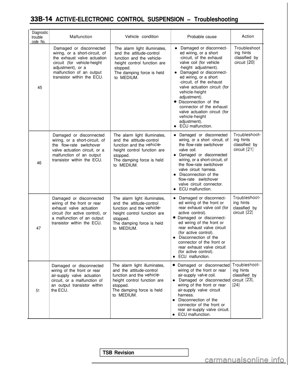
33B-14 ACTIVE-ELECTRONIC CONTROL SUSPENSION - Troubleshooting
DiagnostictroubleMalfunctionVehicle condition
Probable causeAction
code No.
Damaged or disconnected
The alarm light illuminates,l Damaged or disconnect-
Troubleshoot
wiring, or a short-circuit, of and the attitude-control ed wiring, or a shorting hints
the exhaust valve actuation function and the vehicle- -circuit, of the exhaust
classified by
circuit (for vehicle-height height control function are valve coil (for vehicle
circuit
[20]
adjustment), or a
stopped. -height adjustment).
malfunction of an output The damping force is heldl Damaged or disconnect-
transistor within the ECU. to MEDIUM. ed wiring, or a short
-circuit, of the exhaust
45valve actuation circuit (for
vehicle-height
adjustment).
0 Disconnection of the connector of the exhaust
valve actuation circuit (for
vehicle-height
adjustment).
l ECU malfunction.
46
Damaged or disconnected The alarm light illuminates,l Damaged or disconnected Troubleshoot-
wiring, or a short-circuit, of and the attitude-control
wiring, or a short -circuit, ofing hints
the flow-rate switchover function and the
vehicle-the flow-rate switchoverclassified by
valve actuation circuit, or a height control function are
valve coil.circuit [21]
malfunction of an output
stopped.l Damaged or disconnected
transistor within the ECU. The damping force is held wiring, or a short-circuit, of
to MEDIUM. the flow-rate switchover
valve circuit harness.
l Disconnection of the
flow-rate switchover
valve circuit connector.
l ECU malfunction.
47
Damaged or disconnected The alarm light illuminates,l Damaged or disconnect- Troubleshoot-
wiring of the front or rear and the attitude-control ed wiring of the front or
ing hints
exhaust valve actuation function and the
vehicle-rear exhaust valve coil (for
classified by
circuit (for active control), or height control function are active control).
circuit
[22]
a malfunction of an output
stopped.0 Damaged or disconnect-
transistor within the ECU. The damping force is held ed wiring of the front or
to MEDIUM. rear exhaust valve circuit
(for active control).
l Disconnection of the connector of the front or
rear exhaust valve circuit
(for active control).
l ECU malfunction.
51
Damaged or disconnected The alarm light illuminates,0 Damaged or disconnected Troubleshoot-
wiring of the front or rear and the attitude-control wiring of the front or rear
ing hints
air-supply valve actuation function and the
vehicle-air-supply valve
coil. classified by
circuit, or a malfunction of height control function arel Damaged or disconnected circuit
[23],
an output transistor within
stopped. wiring of the front or rear1241
the ECU.
The damping force is held air-supply valve circuit
to MEDIUM. harness.
l Disconnection of the connector of the front or
rear air-supply valve circuit.
l ECU malfunction.
TSB Revision
Page 954 of 1273
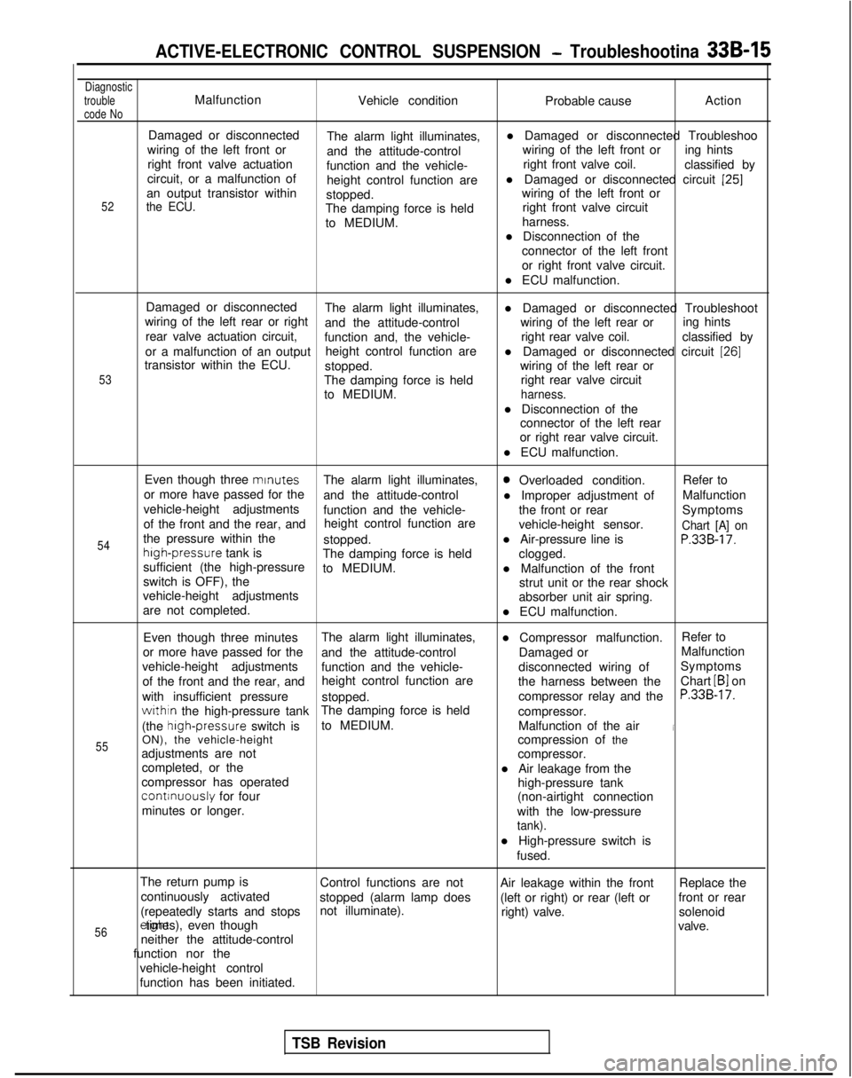
ACTIVE-ELECTRONIC CONTROL SUSPENSION - Troubleshootina 33B-15
Diagnostic
trouble
code NoMalfunction Vehicle condition Probable causeAction
52
Damaged or disconnected
The alarm light illuminates, l Damaged or disconnected Troubleshoo
wiring of the left front or and the attitude-control wiring of the left front or
ing hints
right front valve actuation function and the vehicle- right front valve coil.
classified by
circuit, or a malfunction of height control function arel Damaged or disconnected circuit
[25]an output transistor within
stopped. wiring of the left front orthe ECU.The damping force is held
right front valve circuit
to MEDIUM. harness.
l Disconnection of the connector of the left front
or right front valve circuit.
l ECU malfunction.
53
Damaged or disconnected The alarm light illuminates,
wiring of the left rear or right l Damaged or disconnected Troubleshoot
and the attitude-control wiring of the left rear or
rear valve actuation circuit, ing hints
function and, the vehicle- right rear valve coil.
classified by
or a malfunction of an output height control function are
transistor within the ECU. l Damaged or disconnected circuit
[26]
stopped.
wiring of the left rear or
The damping force is held right rear valve circuit
to MEDIUM.
harness.
l Disconnection of the connector of the left rear
or right rear valve circuit.
l ECU malfunction.
54
55
Even though three mrnutes
The alarm light illuminates,0 Overloaded condition. Refer to
or more have passed for the and the attitude-control l Improper adjustment ofMalfunction
vehicle-height adjustments function and the vehicle- the front or rear
of the front and the rear, and Symptoms
height control function are vehicle-height sensor.
Chart [A] onthe pressure within thestopped.l Air-pressure line isP.33B-17.high-pressure
tank is
The damping force is held
sufficient (the high-pressure clogged.
to MEDIUM. l Malfunction of the front
switch is OFF), the strut unit or the rear shock
vehicle-height adjustments absorber unit air spring.
are not completed. l ECU malfunction.
Even though three minutes The alarm light illuminates,
l Compressor malfunction.Refer to
or more have passed for the and the attitude-control Damaged orMalfunction
vehicle-height adjustments function and the vehicle- disconnected wiring ofSymptoms
of the front and the rear, and height control function are
the harness between theChart
LB1 on
with insufficient pressure stopped. compressor relay and the
P.33B-17.
withtn the high-pressure tankThe damping force is held
compressor.
(the high-pressure
switch isto MEDIUM.
Malfunction of the air
iON), the vehicle-height compression of the
adjustments are not compressor.
completed, or the l Air leakage from the
compressor has operated
continuously for four high-pressure tank
minutes or longer. (non-airtight connection
with the low-pressure
tank).
l High-pressure switch is fused.
The return pump is Control functions are not Air leakage within the frontReplace the
continuously activated stopped (alarm lamp does (left or right) or rear (left orfront or rear
(repeatedly starts and stops not illuminate).
right) valve.solenoid
56erght times), even though
valve.
neither the attitude-control
function nor the
vehicle-height control
function has been initiated.
TSB Revision
Page 955 of 1273
33B-16 ACTIVE-ELECTRONIC CONTROL SUSPENSION - Troubleshooting
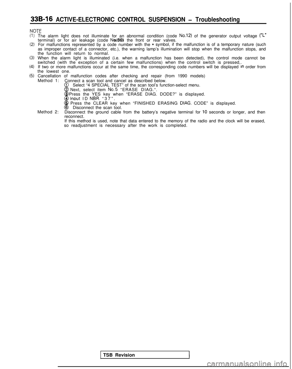
NOT’=
(1)
(2)
13)
(4)
(5)
‘T‘he alarm light does not illuminate for an abnormal condition (code No.12) of the generator output voltage (#,.terminal) or for air leakage (code No.56) within the front or rear valves.
For malfunctions represented by a code number with the* symbol, if the malfunction is of a temporary nature (such
as improper contact of a connector, etc.), the warning lamp’s illumi\
nation will stop when the malfunction stops, and
the function will return to normal.
When the alarm light is illuminated (i.e. when a malfunction has been d\
etected), the control mode cannot be switched (with the exception of a certain few malfunctions) when the c\
ontrol switch is pressed,.
If two or more malfunctions occur at the same time, the corresponding co\
de numbers will be displayed
In order from
the lowest one.
Cancellation of malfunction codes after checking and repair (from 1990 \
models)
Method 1: Connect a scan tool and cancel as described below.
1
w
Select “4 SPECIAL TEST” of the scan tool’s function-select menu\
.2 Next, select item No.5
“ERASE DIAG.“.
3 Press the YES key when “ERASE DIAG. DODE?” is displayed.
4
lnout ID NBR. “37”
.
8
5 Press the CLEAR key when “FINISHED ERASING DIAG. CODE” is displayed.6Disconnect the scan tool.
Method 2: Disconnect the ground cable from the battery’s negative terminal for \
10 seconds or longer, and then
reconnect.
If this method is used, note that data entered to the memory of the radi\
o and the clock will be erased,
so readjustment is necessary after the work is completed.
TSB Revision
1
Page 956 of 1273
![MITSUBISHI GALANT 1989 Service Repair Manual ACTIVE-ELECTRONIC CONTROL SUSPENSION - Troubleshooting 33B-17
CHECKING ACCORDING TO CHARTS CLASSIFIED BY THE MALFUNCTION SYMPTOM
[A] DIAGNOSTIC TROUBLE CODE NO.54
No
Yes
b Excessive vehicle-height ad- MITSUBISHI GALANT 1989 Service Repair Manual ACTIVE-ELECTRONIC CONTROL SUSPENSION - Troubleshooting 33B-17
CHECKING ACCORDING TO CHARTS CLASSIFIED BY THE MALFUNCTION SYMPTOM
[A] DIAGNOSTIC TROUBLE CODE NO.54
No
Yes
b Excessive vehicle-height ad-](/img/19/57312/w960_57312-955.png)
ACTIVE-ELECTRONIC CONTROL SUSPENSION - Troubleshooting 33B-17
CHECKING ACCORDING TO CHARTS CLASSIFIED BY THE MALFUNCTION SYMPTOM
[A] DIAGNOSTIC TROUBLE CODE NO.54
No
Yes
b Excessive vehicle-height ad-justment
(overload) overload). time (due to -Unload the vehicle and turn* the ignition key to OFF; then
restart the engine and check
whether or not the system
functions normally.
Is the installation position of Nothe height sensor correct?
Yes Improper setting of the heightc sensor, or malfunction of the
height sensor. l Correct the installationcposition of the height sen-
sor, or adjust the vehicle
-height sensor rod.
l Check the height sensor. Refer to troubleshooting
hints [IO] and
[ll]classified by circuit.
Are the front strut and rear
NoMalfunction of the rolling
shock absorber unit air spr-* diaphragm.
Repair the rolling diaphragm,
or replace the shock absorber
ings in normal condition?Lunit.
(become folded)
Yes
Is the sound of operation
NoThe solenoid valves remain
heard from each solenoid closed, or there is air leakage
valve necessary for th
e
’ due to a malfunction of the
vehicle-height adjustment? valve seat.
Yes
Is the air pressure in the
vehicle-height adjustment
Nopressure line 950 kPa (135
psi) or higher?
I
Yes Damaged or disconnected
wiring of the high-pressure
switch, or incorrect vehicle
-height adjustment pressureline.
l Check the high-pressure switch circuit.
* Refer to troubleshooting hint [5] classified by circuit.
l Correct the clogging pro-
blem, or replace the air
tube.
Control unit malfunction.
[B] DIAGNOSTIC TROUBLE CODE NO.55
- No
Does the compressor func-
tion normally?
Yes Replace the control unit.c l Power is not supplied to
the compressor.Refer to troubleshooting
hint
[18] classified by cir-
cuit.
0 Improper compressor com- pression.
Is the air pressure in the
Novehicle-height adjustment
pressure line 760 kPa (108psi) or lower? High-pressure
switch
isRefer to troubleshooting hint
shorted____* [5] classified by circuit.
Yes Air leakage.
TSB RevisionI
Page 957 of 1273
33B-18 ACTIVE-ELECTRONIC CONTROL SUSPENSION - Troubleshooting
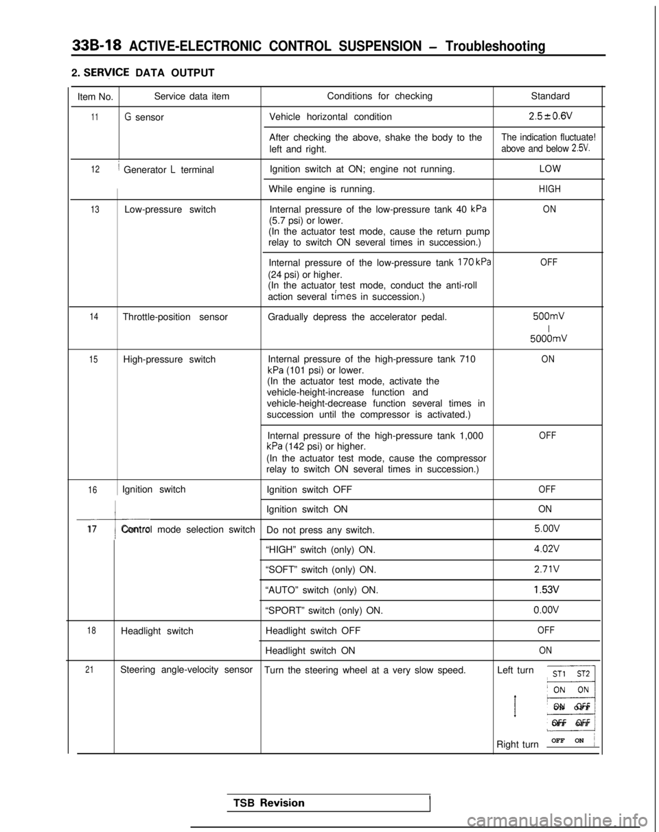
2. SERlflCE DATA OUTPUT
Item No. Service data item
Conditions for checking
Standard
11G sensorVehicle horizontal condition2.520.6V
After checking the above, shake the body to theThe indication fluctuate!
left and right.above and below 2.5V.
12/ Generator L terminalIgnition switch at ON; engine not running.LOW
While engine is running.HIGH
13Low-pressure switch
Internal pressure of the low-pressure tank 40 kPaON
(5.7 psi) or lower.
(In the actuator test mode, cause the return pump
relay to switch ON several times in succession.)
Internal pressure of the low-pressure tank
170 kPa
(24 psi) or higher.
(In the actuator test mode, conduct the anti-roll
action several
times in succession.)
OFF
14Throttle-position sensor Gradually depress the accelerator pedal. 500mV
I
5000mV
15High-pressure switch
Internal pressure of the high-pressure tank 710ON
kPa (101 psi) or lower.
(In the actuator test mode, activate the
vehicle-height-increase function and
vehicle-height-decrease function several times in
succession until the compressor is activated.)
Internal pressure of the high-pressure tank 1,000
kPa (142 psi) or higher.
OFF
(In the actuator test mode, cause the compressor
relay to switch ON several times in succession.)
16Ignition switch Ignition switch OFFOFF
I
Ignition switch ONON
17Control mode selection switch
Do not press any switch. 5.oov
“HIGH” switch (only) ON.
4.02V
“SOFT” switch (only) ON.2.71V
“AUTO” switch (only) ON.1.53V
“SPORT” switch (only) ON.o.oov
18Headlight switch Headlight switch OFFOFF
Headlight switch ONON
21Steering angle-velocity sensor
Turn the steering wheel at a very slow speed. Left turnST1 ST2
__I
’ E3
ON OF
F
OFF OFF
Right turn OFF ON
j
TSB Revisio.nI
Page 958 of 1273
ACTIVE-ELECTRONIC CONTROL SUSPENSION - Troubleshootina 33B-19
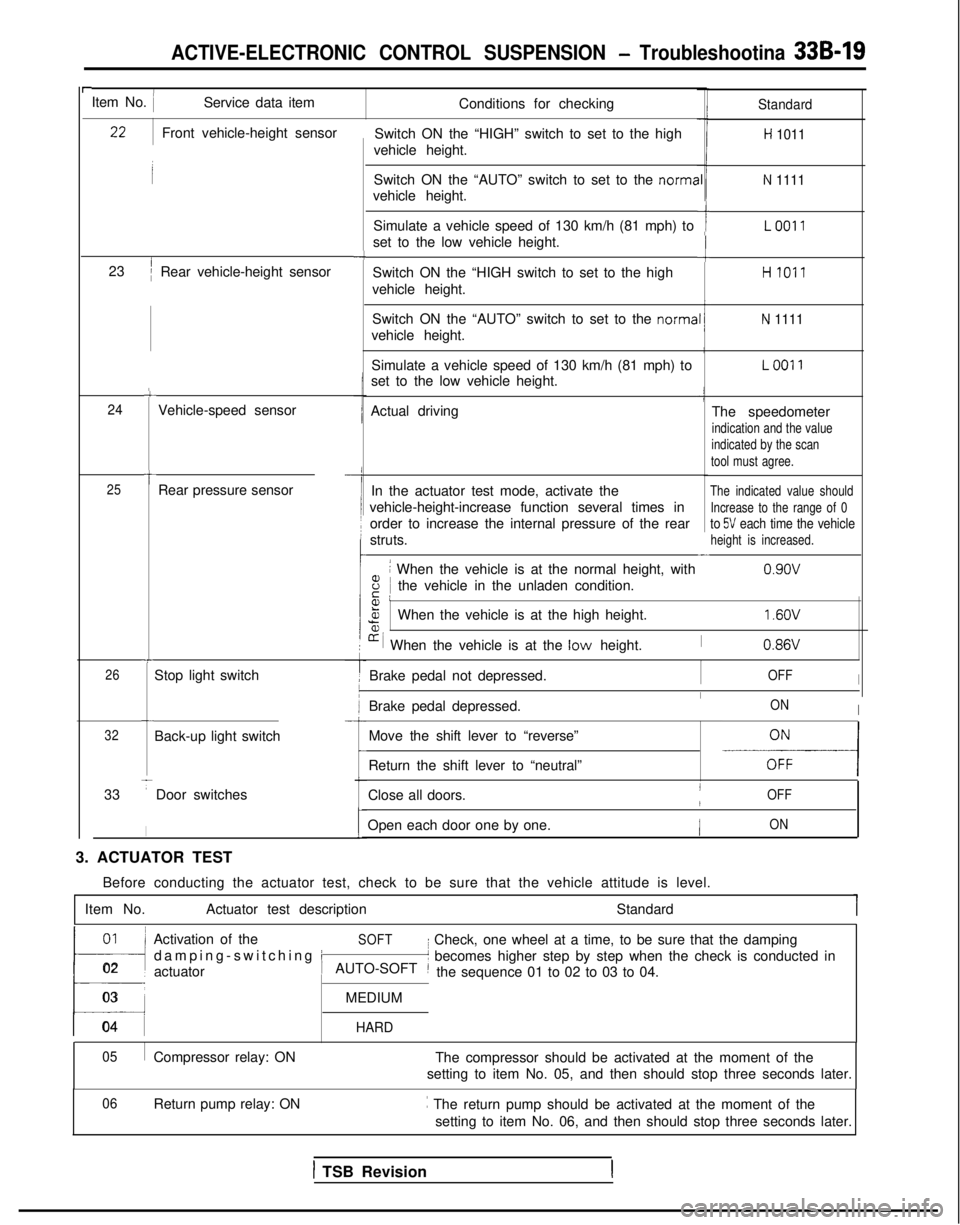
rItem No. IService data itemConditions for checking
Switch ON the “HIGH” switch to set to the high
vehicle height.Standard
H 1011
Switch ON the “AUTO” switch to set to the norma
vehicle height.N 1111
Simulate a vehicle speed of 130 km/h (81 mph) to
set to the low vehicle height.ILO011
-cSwitch ON the “HIGH switch to set to the high
vehicle height.HI011
Switch ON the “AUTO” switch to set to the norma
vehicle height.
N 1111
Simulate a vehicle speed of 130 km/h (81 mph) to
set to the low vehicle height.LOO11
Actual driving The speedometer
indication and the value
indicated by the scan
tool must agree.
In the actuator test mode, activate theThe indicated value should
vehicle-height-increase function several times inIncrease to the range of 0
order to increase the internal pressure of the rearto 5V each time the vehicle
struts.height is increased.-
8
i When the vehicle is at the normal height, with
iE Ithe vehicle in the unladen condition. 0.9ov
Front vehicle-height sensor
23
’/Rear vehicle-height sensor
-4
c
24Vehicle-speed sensor
t25Rear pressure sensor
Fa,%When the vehicle is at the high height.
[r i When the vehicle is at the low height.
1.6OV
I0.86VT
26Stop light switch Brake pedal not depressed.IOFFI
Brake pedal depressed.IONIc
32Back-up light switch
33
TDoor switches
I
Move the shift lever to “reverse”
-E-----l
-
Return the shift lever to “neutral”
Close all doors.
IOFF/
Open each door one by one.ION
3. ACTUATOR TEST Before conducting the actuator test, check to be sure that the vehicle a\
ttitude is level.
Item No. Actuator test description Standard
01~
!l
Activation of theSOFT
damping-switching i
I Check, one wheel at a time, to be sure that the damping
02 actuator
t’ becomes higher step by step when the check is conducted in
AUTO-SOFT ~the sequence 01 to 02 to 03 to 04.
03MEDIUM
04 HARD
05
Compressor relay: ON The compressor should be activated at the moment of the
setting to item No. 05, and then should stop three seconds later.
Return pump relay: ON ~
The return pump should be activated at the moment of the
setting to item No. 06, and then should stop three seconds later.
06
1 TSB Revision
Page 959 of 1273
33B-20 ACTIVE-ELECTRONIC CONTROL SUSPENSION - Troubleshooting
IFr.o5;
L”975
%2xa-0s
iz2
P.-x
E.”.km5r
a,G2B.I?.C
22In
s.-5G0”
2.EF
TSB Revision
Page 960 of 1273
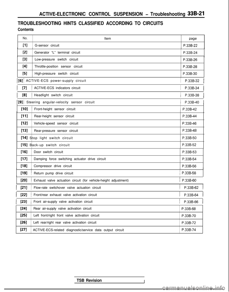
ACTIVE-ELECTRONIC CONTROL SUSPENSION - Troubleshooting 33B-21
TROUBLESHOOTING HINTS CLASSIFIED ACCORDING TO CIRCUITS
Contents
No.
PIG-sensor circuitItem
paw
P.33B-22/IPI
Generator “L” terminal circuit
P.33B-24
[31Low-pressure switch circuitP.33B-26
I41Throttle-position sensor circuitP.33B-28
[51High-pressure switch circuit P.338-30
) [6] / ACTIVE-ECS power-supply circuit
I PI IACTIVE-ECS indicators circuit
1 P.33B-32 1
1
P.33B-34 1
/ P.33B-38 1I L81 IHeadlight switch circuit
1 [9] / Steering angular-velocity sensor circuit/ P.33B-40 1
[lOI /
I
Front-height sensor circuit( P:33B-42I
PIIRear-height sensor circuit
[I21Vehicle-speed sensor circuit
[13]Rear-pressure sensor circuit
[I41 Stop light switch circuit
[I51 Back-up switch circuit
P.33B-44
P.33B46
P.33B-48 P.338-50
P.33B-52
TSB RevisionI
[If31Door switch circuitP.33B-53
[17]Damping force switching actuator drive circuit
P.338-54
1181Compressor drive circuitP.33B-561
WI
I
I
Return pump drive circuit/ P.33B-58
ml /
I
Exhaust valve actuation circuit (for vehicle-height adjustment)/ P.33B-60
I PII /Flow-rate switchover valve actuation circuit/ P.33B-62 1
I WI /Front/rear exhaust valve activation circuit1 P.33B-64 I
( 1231 1Front air-supply valve activation circuit1 P.33B-66 1
1241Rear air-supply valve activation circuitP.33B-68
[25]Left front/right front valve activation circuitP.33B-70
[=ILeft rear/right rear valve activation circuitP.33B-72
[271ACTIVE-ECS-related diagnostic/service data output circuitP.33B-74