MITSUBISHI L200 2004 (in English) Repair Manual
Manufacturer: MITSUBISHI, Model Year: 2004, Model line: L200, Model: MITSUBISHI L200 2004Pages: 264, PDF Size: 4.14 MB
Page 61 of 264
SEAT AND SEAT BELTS
3-29
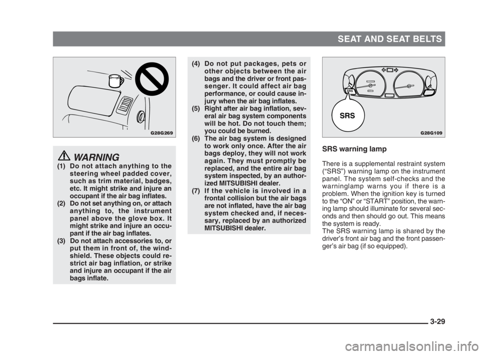
WARNING(1) Do not attach anything to the
steering wheel padded cover,
such as trim material, badges,
etc. It might strike and injure an
occupant if the air bag inflates.
(2) Do not set anything on, or attach
anything to, the instrument
panel above the glove box. It
might strike and injure an occu-
pant if the air bag inflates.
(3) Do not attach accessories to, or
put them in front of, the wind-
shield. These objects could re-
strict air bag inflation, or strike
and injure an occupant if the air
bags inflate.
SRS warning lamp
There is a supplemental restraint system
(“SRS”) warning lamp on the instrument
panel. The system self-checks and the
warninglamp warns you if there is a
problem. When the ignition key is turned
to the “ON” or “START” position, the warn-
ing lamp should illuminate for several sec-
onds and then should go out. This means
the system is ready.
The SRS warning lamp is shared by the
driver’s front air bag and the front passen-
ger’s air bag (if so equipped).
(4) Do not put packages, pets or
other objects between the air
bags and the driver or front pas-
senger. It could affect air bag
performance, or could cause in-
jury when the air bag inflates.
(5) Right after air bag inflation, sev-
eral air bag system components
will be hot. Do not touch them;
you could be burned.
(6) The air bag system is designed
to work only once. After the air
bags deploy, they will not work
again. They must promptly be
replaced, and the entire air bag
system inspected, by an author-
ized MITSUBISHI dealer.
(7) If the vehicle is involved in a
frontal collision but the air bags
are not inflated, have the air bag
system checked and, if neces-
sary, replaced by an authorized
MITSUBISHI dealer.
G28G269G28G109
SRS
SRS
03engL2_240082_4 22-01-2004 13:01 Page 3-29
Page 62 of 264
SEAT AND SEAT BELTS
3-30
WARNINGIf any of following conditions occur,
the SRS is not working properly, and
you should immediately have it in-
spected by an authorized MITSU-
BISHI dealer.
• The SRS warning lamp does not il-
luminate when you start the vehi-
cle.
• The SRS warning lamp does not
go out after several seconds.
• The SRS warning lamp illuminates
while driving.
SRS servicing
The entire SRS system must be inspected
by an authorized MITSUBISHI dealer at
10 years.
WARNING(1) Any maintenance performed on
or near the components of the
SRS must be performed only by
an authorized MITSUBISHI
dealer. Do not permit anyone
else to do service, inspection,
maintenance or repair on any
SRS components or wiring; sim-
ilarly, no part of the SRS system
should ever be handled or dis-
posed of by anyone except an
authorized MITSUBISHI dealer.
Improper work on the SRS com-
ponents or wiring could result in
inadvertent deployment of the air
bag, or could render the SRS sys-
tem inoperative; either situation
could result in serious injury.
(2)Do not modify your steering
wheel or any other SRS compo-
nents. For example, replacement
of the steering wheel, or modifi-
cations to the front bumper or
body structure can adversely af-
fect SRS performance and lead
to possible injury.
(3) If your vehicle has received any
front - end damage, you should
have the SRS inspected by an
authorized MITSUBISHI dealer
to ensure it is in proper working
order.
NOTE
(1) When you transfer ownership of the
vehicle to some other person, we
urge you to alert the new owner that it
is equipped with the SRS and refer
that owner to the applicable section in
this owner’s manual.
(2) If you junk or scrap the vehicle, we
urge you to first take the vehicle to an
authorized MITSUBISHI dealer so
that the SRS can be rendered safe.
03engL2_240082_4 22-01-2004 13:01 Page 3-30
Page 63 of 264
SEAT AND SEAT BELTS
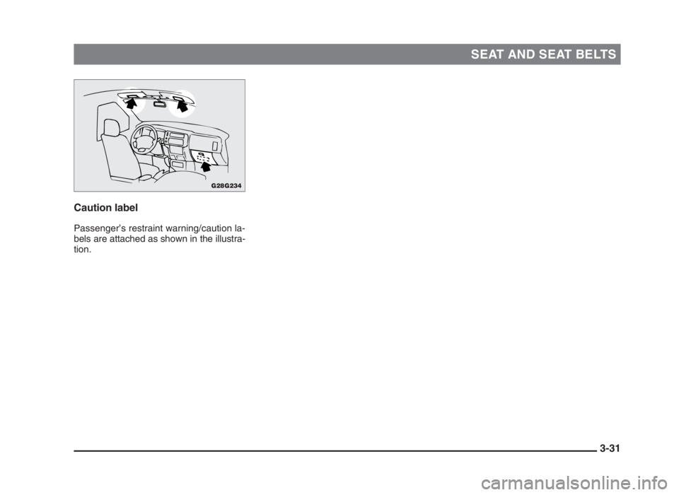
3-31 Caution label
Passenger’s restraint warning/caution la-
bels are attached as shown in the illustra-
tion.
G28G234
03engL2_240082_4 22-01-2004 13:01 Page 3-31
Page 64 of 264
03engL2_240082_4 22-01-2004 13:01 Page 3-32
Page 65 of 264
Instruments .................................................. 4-2
Speedometer ................................................ 4-2
Odometer/Tripmeter .................................... 4-3
Tachometer................................................... 4-3
Fuel gauge .................................................... 4-3
Water temperature gauge............................ 4-4
Inclinometer* ................................................ 4-4
Thermometer*............................................... 4-5
Volt meter* .................................................... 4-5
Indication and warning lamps .................... 4-6
Combination headlamps, dipper and turn
signal switch .......................................... 4-12
Headlamp levelling switch* ......................... 4-14
Windscreen wiper and washer switch ....... 4-15
Headlamp washer switch* ........................... 4-17
Hazard warning flasher switch ................... 4-18
Rear window demister switch* ................... 4-18
Rear fog lamp switch* ................................. 4-19
Rheostat (meter illumination control)* ....... 4-20
Horn switch .................................................. 4-20
Room lamps ................................................. 4-20
Instruments and controls
4
04engL2_240082_4 22-01-2004 13:19 Page 4-1
Page 66 of 264
INSTRUMENTS AND CONTROLS
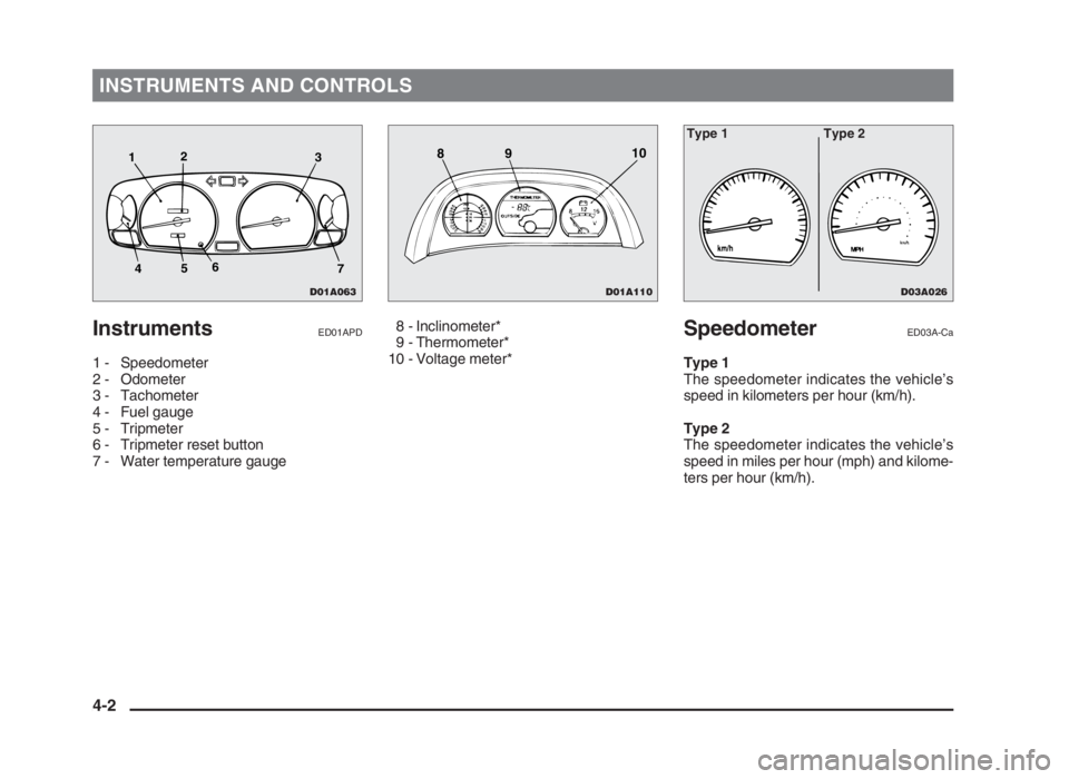
InstrumentsED01APD
1 - Speedometer
2 - Odometer
3 - Tachometer
4 - Fuel gauge
5 - Tripmeter
6 - Tripmeter reset button
7 - Water temperature gauge8 - Inclinometer*
9 - Thermometer*
10 - Voltage meter*
SpeedometerED03A-Ca
Type 1
The speedometer indicates the vehicle’s
speed in kilometers per hour (km/h).
Type 2
The speedometer indicates the vehicle’s
speed in miles per hour (mph) and kilome-
ters per hour (km/h).
4-2
D01A063
12
3
7 456
D03A026
Type 1 Type 2
D01A110
8910
04engL2_240082_4 22-01-2004 13:19 Page 4-2
Page 67 of 264
INSTRUMENTS AND CONTROLS
Odometer/TripmeterED03B-Fa
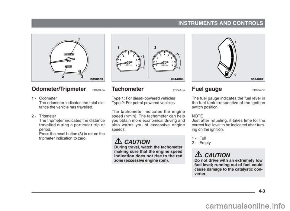
1 - Odometer
The odometer indicates the total dis-
tance the vehicle has travelled.
2 - Tripmeter
The tripmeter indicates the distance
travelled during a particular trip or
period.
Press the reset button (3) to return the
tripmeter indication to zero.
Fuel gaugeED05A-Cd
The fuel gauge indicates the fuel level in
the fuel tank irrespective of the ignition
switch position.
NOTE
Just after refueling, it takes time for the
correct fuel level to be indicated after turn-
ing on the ignition.
1 - Full
2 - Empty
CAUTIONDo not drive with an extremely low
fuel level; running out of fuel could
cause damage to the catalystic con-
verter.
TachometerED04A-Ja
Type 1: For diesel-powered vehicles
Type 2: For petrol-powered vehicles
The tachometer indicates the engine
speed (r/min). The tachometer can help
you obtain more economical driving and
also warns you of excessive engine
speeds.
CAUTIONDuring travel, watch the tachometer
making sure that the engine speed
indication does not rise to the red
zone (excessive engine rpm).
4-3
D04A038
12
D03B003
1
23
D05A007
1
2
04engL2_240082_4 22-01-2004 13:19 Page 4-3
Page 68 of 264
INSTRUMENTS AND CONTROLS
Water temperature gauge
ED06A-R
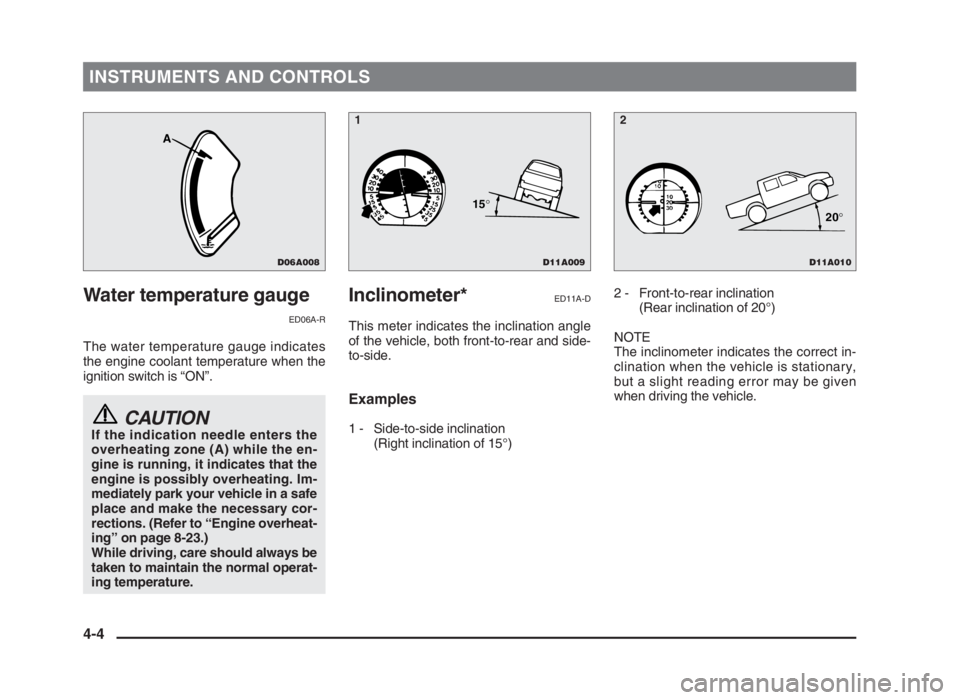
The water temperature gauge indicates
the engine coolant temperature when the
ignition switch is “ON”.
CAUTIONIf the indication needle enters the
overheating zone (A) while the en-
gine is running, it indicates that the
engine is possibly overheating. Im-
mediately park your vehicle in a safe
place and make the necessary cor-
rections. (Refer to “Engine overheat-
ing” on page 8-23.)
While driving, care should always be
taken to maintain the normal operat-
ing temperature.
Inclinometer*ED11A-D
This meter indicates the inclination angle
of the vehicle, both front-to-rear and side-
to-side.
Examples
1 - Side-to-side inclination
(Right inclination of 15°)2 - Front-to-rear inclination
(Rear inclination of 20°)
NOTE
The inclinometer indicates the correct in-
clination when the vehicle is stationary,
but a slight reading error may be given
when driving the vehicle.
4-4
D11A009
15°
D11A010
20°
D06A008
A
12
04engL2_240082_4 22-01-2004 13:19 Page 4-4
Page 69 of 264
INSTRUMENTS AND CONTROLS
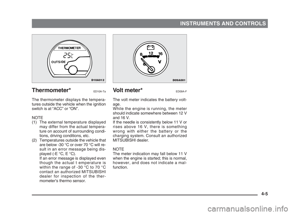
Thermometer*ED10A-Ta
The thermometer displays the tempera-
tures outside the vehicle when the ignition
switch is at “ACC” or “ON”.
NOTE
(1) The external temperature displayed
may differ from the actual tempera-
ture on account of surrounding condi-
tions, driving conditions, etc.
(2) Temperatures outside the vehicle that
are below -30 °C or over 70 °C will re-
sult in an error message being dis-
played (-E °C, E °C).
If an error message is displayed even
though the actual t emperature is
within the range of -30 °C to 70 °C
contact an authorized MITSUBISHI
dealer for inspection of the ther-
mometer’s thermo sensor.
Volt meter*ED09A-F
The volt meter indicates the battery volt-
age.
While the engine is running, the meter
should indicate somewhere between 12 V
and 16 V.
If the needle is consistently below 11 V or
rises above 16 V, there is something
wrong with either the battery or the
charging system. Consult an authorized
MITSUBISHI dealer.
NOTE
The meter indication may fall below 11 V
when the engine is started; this is normal,
however, and does not indicate a mal-
function.
4-5
D10A012D09A001
04engL2_240082_4 22-01-2004 13:19 Page 4-5
Page 70 of 264
INSTRUMENTS AND CONTROLS
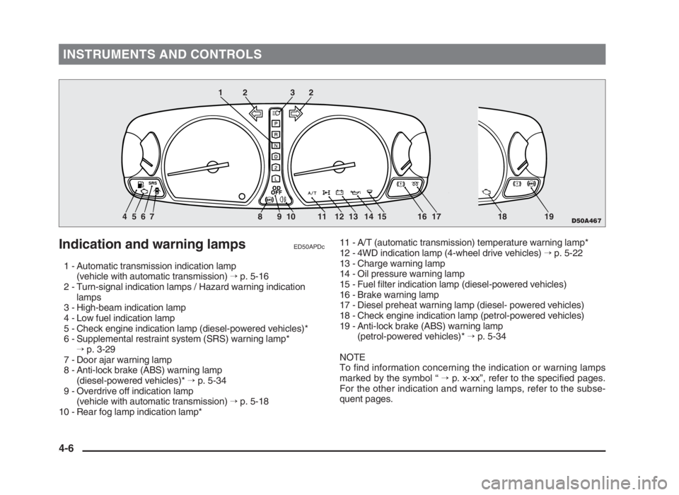
Indication and warning lampsED50APDc
1 - Automatic transmission indication lamp
(vehicle with automatic transmission) →p. 5-16
2 - Turn-signal indication lamps / Hazard warning indication
lamps
3 - High-beam indication lamp
4 - Low fuel indication lamp
5 - Check engine indication lamp (diesel-powered vehicles)*
6 - Supplemental restraint system (SRS) warning lamp*
→p. 3-29
7 - Door ajar warning lamp
8 - Anti-lock brake (ABS) warning lamp
(diesel-powered vehicles)* →p. 5-34
9 - Overdrive off indication lamp
(vehicle with automatic transmission) →p. 5-18
10 - Rear fog lamp indication lamp*11 - A/T (automatic transmission) temperature warning lamp*
12 - 4WD indication lamp (4-wheel drive vehicles) →p. 5-22
13 - Charge warning lamp
14 - Oil pressure warning lamp
15 - Fuel filter indication lamp (diesel-powered vehicles)
16 - Brake warning lamp
17 - Diesel preheat warning lamp (diesel- powered vehicles)
18 - Check engine indication lamp (petrol-powered vehicles)
19 - Anti-lock brake (ABS) warning lamp
(petrol-powered vehicles)* →p. 5-34
NOTE
To find information concerning the indication or warning lamps
marked by the symbol “ →p. x-xx”, refer to the specified pages.
For the other indication and warning lamps, refer to the subse-
quent pages.
4-6
D50A467
12 32
4 5 6 7 8 9 10 11 12 13 14 15 16 17 18 19
04engL2_240082_4 22-01-2004 13:19 Page 4-6