heater MITSUBISHI LANCER 2005 Workshop Manual
[x] Cancel search | Manufacturer: MITSUBISHI, Model Year: 2005, Model line: LANCER, Model: MITSUBISHI LANCER 2005Pages: 788, PDF Size: 45.98 MB
Page 582 of 788
REFRIGERANT LINE
HEATER, AIR CONDITIONER AND VENTILATION55-98
REFRIGERANT LINE
REMOVAL AND INSTALLATION
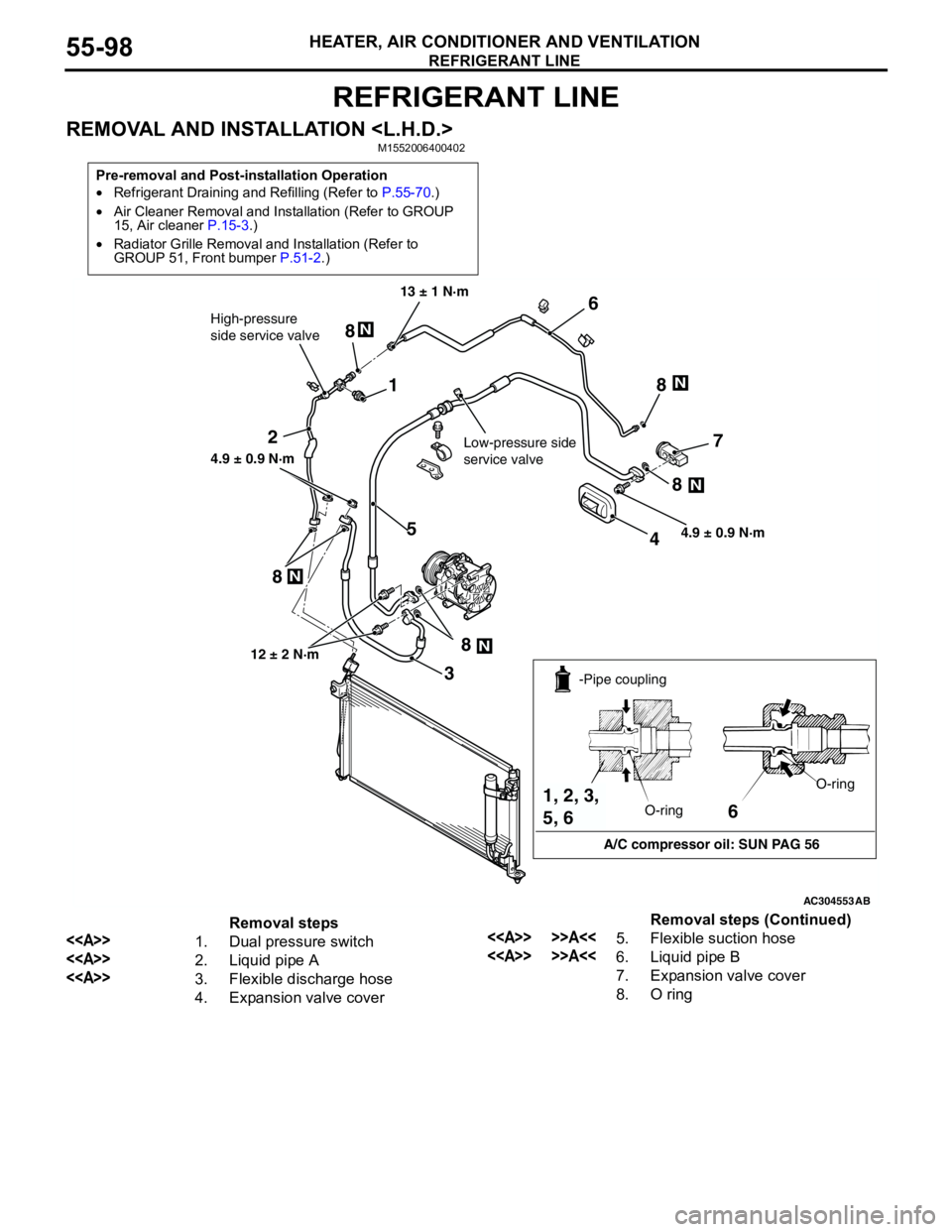
Pre-removal and Post-installation Operation
•Refrigerant Draining and Refilling (Refer to P.55-70.)
•Air Cleaner Removal and Installation (Refer to GROUP
15, Air cleaner P.15-3.)
•Radiator Grille Removal and Installation (Refer to
GROUP 51, Front bumper P.51-2.)
AC304553
1
2
3
45
6
7
8N
N
N
N
N
8 8
8
8
High-pressure
side service valve
Low-pressure side
service valve
4.9 ± 0.9 N·m 13 ± 1 N·m
4.9 ± 0.9 N·m
12 ± 2 N·m
AB
6
A/C compressor oil: SUN PAG 56 -Pipe coupling
O-ringO-ring
1, 2, 3,
5, 6
Removal steps
<>1. Dual pressure switch
<>2. Liquid pipe A
<>3. Flexible discharge hose
4. Expansion valve cover
<> >>A<<5. Flexible suction hose
<> >>A<<6. Liquid pipe B
7. Expansion valve cover
8. O ringRemoval steps (Continued)
Page 583 of 788
REFRIGERANT LINE
HEATER, AIR CONDITIONER AND VENTILATION55-99
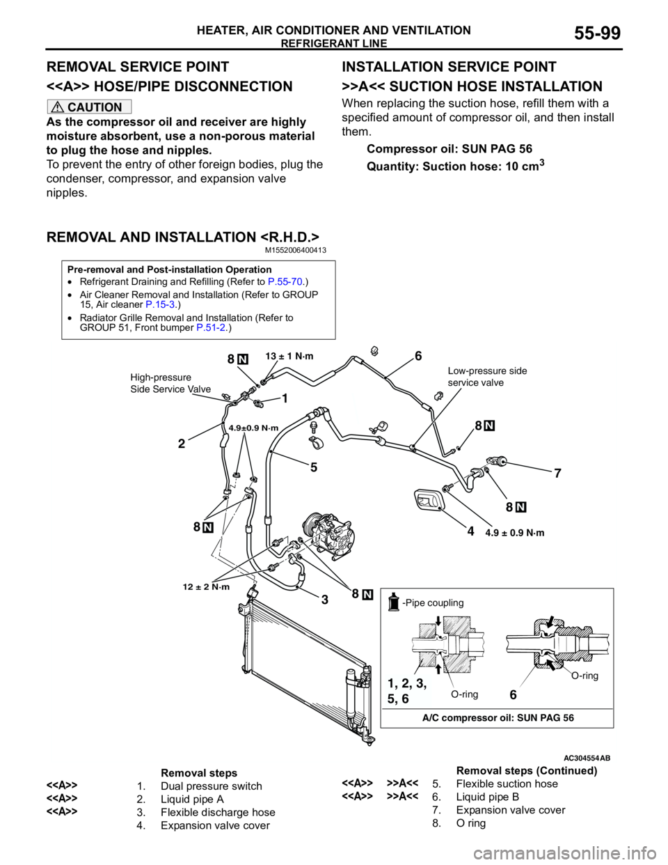
REMOVAL SERVICE POINT
<> HOSE/PIPE DISCONNECTION
CAUTION
As the compressor oil and receiver are highly
moisture absorbent, use a non-porous material
to plug the hose and nipples.
To prevent the entry of other foreign bodies, plug the
condenser, compressor, and expansion valve
nipples.
INSTALLATION SERVICE POINT
>>A<< SUCTION HOSE INSTALLATION
When replacing the suction hose, refill them with a
specified amount of compressor oil, and then install
them.
Compressor oil: SUN PAG 56
Quantity: Suction hose: 10 cm
3
REMOVAL AND INSTALLATION
Pre-removal and Post-installation Operation
•Refrigerant Draining and Refilling (Refer to P.55-70.)
•Air Cleaner Removal and Installation (Refer to GROUP
15, Air cleaner P.15-3.)
•Radiator Grille Removal and Installation (Refer to
GROUP 51, Front bumper P.51-2.)
AC304554
1
2
3
4
5
6
7
8N
8N
8N
N8 8
N
4.9±0.9 N·m
Low-pressure side
service valve 13 ± 1 N·mHigh-pressure
Side Service Valve
12 ± 2 N·m
4.9 ± 0.9 N·m
AB
6
A/C compressor oil: SUN PAG 56 -Pipe coupling
O-ringO-ring
1, 2, 3,
5, 6
Removal steps
<>1. Dual pressure switch
<>2. Liquid pipe A
<>3. Flexible discharge hose
4. Expansion valve cover
<> >>A<<5. Flexible suction hose
<> >>A<<6. Liquid pipe B
7. Expansion valve cover
8. O ringRemoval steps (Continued)
Page 584 of 788

REFRIGERANT LINE
HEATER, AIR CONDITIONER AND VENTILATION55-100
REMOVAL SERVICE POINT
<> HOSE/PIPE DISCONNECTION
CAUTION
As the compressor oil and receiver are highly
moisture absorbent, use a non-porous material
to plug the hose and nipples.
To prevent the entry of other foreign bodies, plug the
condenser, compressor, and expansion valve
nipples.
INSTALLATION SERVICE POINT
>>A<< SUCTION HOSE INSTALLATION
When replacing the suction hose, refill them with a
specified amount of compressor oil, and then install
them.
Compressor oil: SUN PAG 56
Quantity: Suction hose: 10 cm
3
Page 585 of 788
DUCTS
HEATER, AIR CONDITIONER AND VENTILATION55-101
DUCTS
REMOVAL AND INSTALLATIONM1553001000101
AC304890
7
8
13
12 11 109364 5 4
3
2
1
AB A
A
Clip
Instrument panel
1 Cross-section A-A
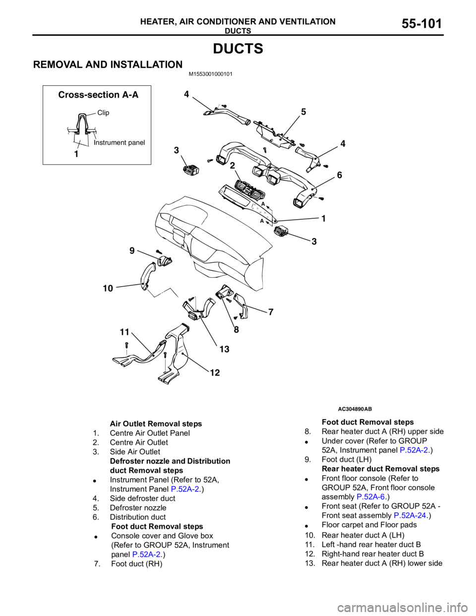
Air Outlet Removal steps
1. Centre Air Outlet Panel
2. Centre Air Outlet
3. Side Air Outlet
Defroster nozzle and Distribution
duct Removal steps
•Instrument Panel (Refer to 52A,
Instrument Panel P.52A-2.)
4. Side defroster duct
5. Defroster nozzle
6. Distribution duct
Foot duct Removal steps
•Console cover and Glove box
(Refer to GROUP 52A, Instrument
panel P.52A-2.)
7. Foot duct (RH)8. Rear heater duct A (RH) upper side
•Under cover (Refer to GROUP
52A, Instrument panel P.52A-2.)
9. Foot duct (LH)
Rear heater duct Removal steps
•Front floor console (Refer to
GROUP 52A, Front floor console
assembly P.52A-6.)
•Front seat (Refer to GROUP 52A -
Front seat assembly P.52A-24.)
•Floor carpet and Floor pads
10. Rear heater duct A (LH)
11. Left -hand rear heater duct B
12. Right-hand rear heater duct B
13. Rear heater duct A (RH) lower sideFoot duct Removal steps
Page 586 of 788
VENTILATORS
HEATER, AIR CONDITIONER AND VENTILATION55-102
VENTILATORS
REMOVAL AND INSTALLATIONM1553001600318
AC304949
Cross-Section A-A Cross-Section B-B
1
11
Claw
Claw
A
A
B
B
A
A
AB
AC3049511
A
A
B
B
A
A
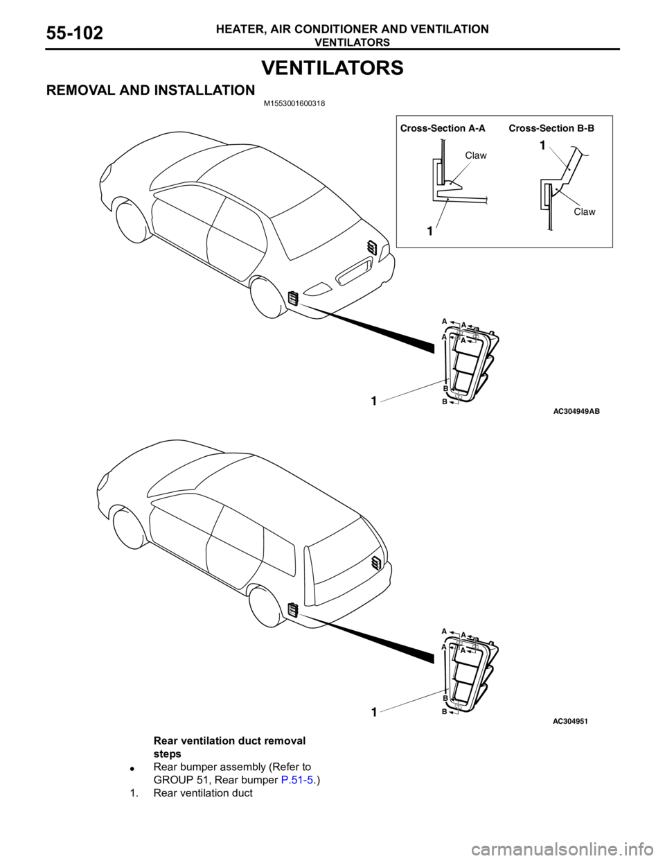
Rear ventilation duct removal
steps
•Rear bumper assembly (Refer to
GROUP 51, Rear bumper P.51-5.)
1. Rear ventilation duct
Page 623 of 788
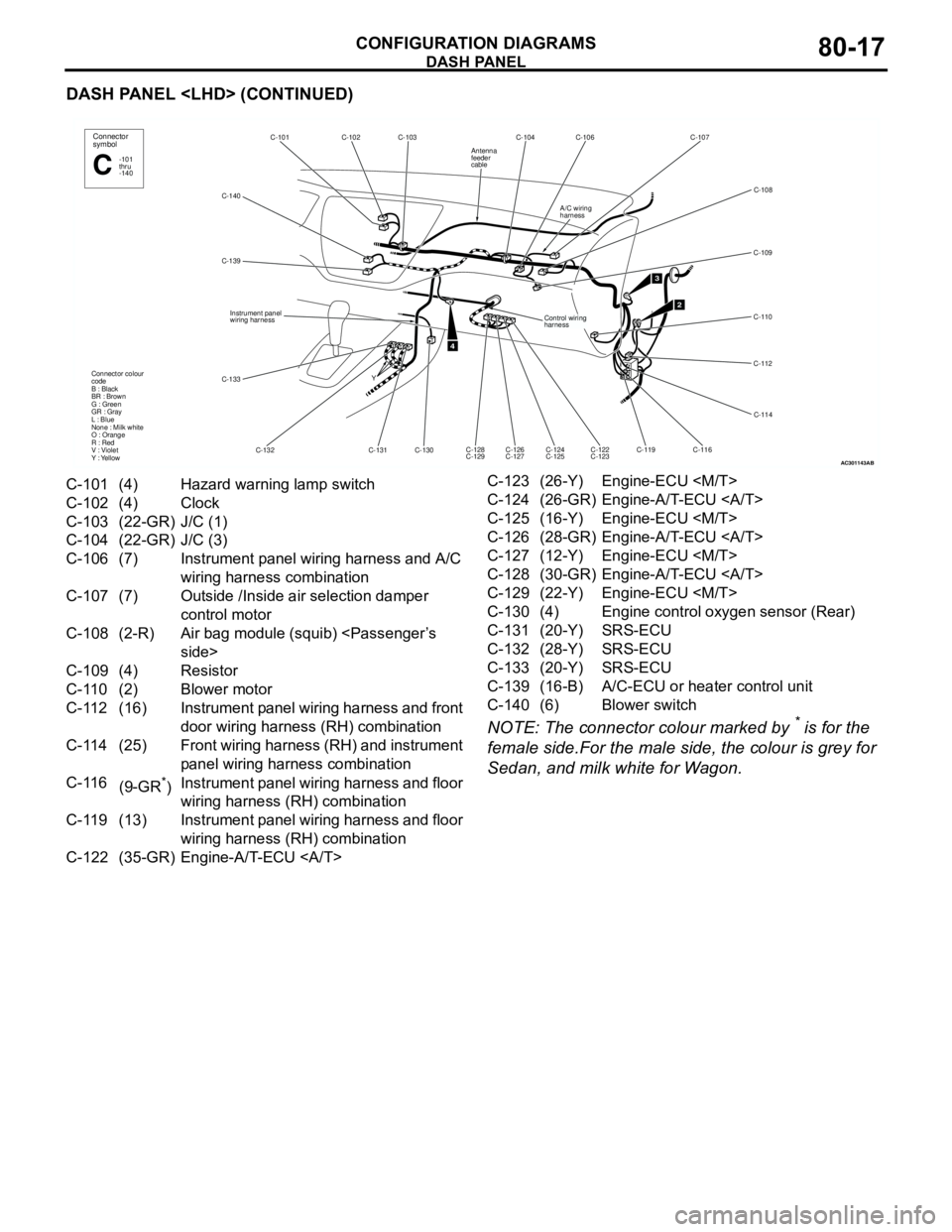
DASH PANEL
CONFIGURATION DIAGRAMS80-17
DASH PANEL
NOTE: The connector colour marked by
* is for the
female side.For the male side, the colour is grey for
Sedan, and milk white for Wagon.
AC301143
C-140C-102C-103 C-101
C-132 C-139
C-130 Y
4
Connector
symbol
-101
thru
-140C
Connector colour
code
B : Black
BR : Brown
G : Green
GR : Gray
L : Blue
None : Milk white
O : Orange
R : Red
V : Violet
Y : Yellow
Instrument panel
wiring harness
C-131
C-133
AB
C-104 C-106 C-107
C-109
C-110
C-112
C-114
C-116
C-119 C-126
C-127 C-128
C-129
2
C-108
C-124
C-125C-122
C-123
3
Control wiring
harness
A/C wiring
harness
Antenna
feeder
cable
C-101 (4) Hazard warning lamp switch
C-102 (4) Clock
C-103 (22-GR) J/C (1)
C-104 (22-GR) J/C (3)
C-106 (7) Instrument panel wiring harness and A/C
wiring harness combination
C-107 (7) Outside /Inside air selection damper
control motor
C-108 (2-R) Air bag module (squib)
C-109 (4) Resistor
C-110 (2) Blower motor
C-112 (16) Instrument panel wiring harness and front
door wiring harness (RH) combination
C-114 (25) Front wiring harness (RH) and instrument
panel wiring harness combination
C-116
(9-GR
*)Instrument panel wiring harness and floor
wiring harness (RH) combination
C-119 (13) Instrument panel wiring harness and floor
wiring harness (RH) combination
C-122 (35-GR) Engine-A/T-ECU C-123 (26-Y) Engine-ECU
C-124 (26-GR) Engine-A/T-ECU
C-125 (16-Y) Engine-ECU
C-126 (28-GR) Engine-A/T-ECU
C-127 (12-Y) Engine-ECU
C-128 (30-GR) Engine-A/T-ECU
C-129 (22-Y) Engine-ECU
C-130 (4) Engine control oxygen sensor (Rear)
C-131 (20-Y) SRS-ECU
C-132 (28-Y) SRS-ECU
C-133 (20-Y) SRS-ECU
C-139 (16-B) A/C-ECU or heater control unit
C-140 (6) Blower switch
Page 626 of 788
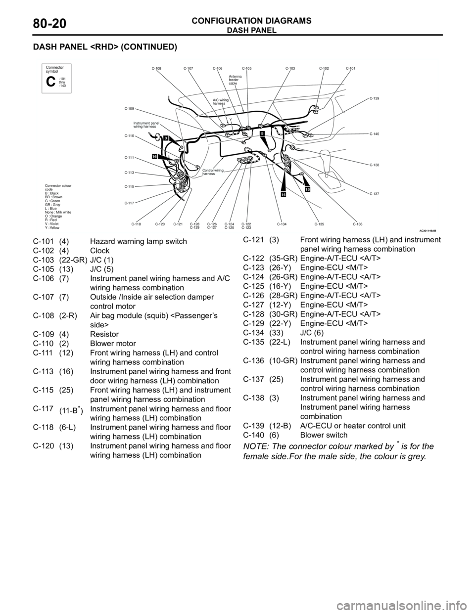
DASH PANEL
CONFIGURATION DIAGRAMS80-20
DASH PANEL
NOTE: The connector colour marked by
* is for the
female side.For the male side, the colour is grey.
AC301146
Y
16
C-105 C-106 C-107 C-108
A/C wiring
harness
C-109
C-110
C-111
C-113
C-115
C-117
Instrument panel
wiring harness
Control wiring
harness
C-118C-120
C-121
C-128
C-129C-126
C-127C-124
C-125C-122
C-123 Connector colour
code
B : Black
BR : Brown
G : Green
GR : Gray
L : Blue
None : Milk white
O : Orange
R : Red
V : Violet
Y : Yellow
3
Connector
symbol
-101
thru
-140C
Antenna
feeder
cable
AB
5
1415
C-103
C-102
C-101
C-139
C-138
C-137 C-140
C-136 C-135
C-134
C-101 (4) Hazard warning lamp switch
C-102 (4) Clock
C-103 (22-GR) J/C (1)
C-105 (13) J/C (5)
C-106 (7) Instrument panel wiring harness and A/C
wiring harness combination
C-107 (7) Outside /Inside air selection damper
control motor
C-108 (2-R) Air bag module (squib)
C-109 (4) Resistor
C-110 (2) Blower motor
C-111 (12) Front wiring harness (LH) and control
wiring harness combination
C-113 (16) Instrument panel wiring harness and front
door wiring harness (LH) combination
C-115 (25) Front wiring harness (LH) and instrument
panel wiring harness combination
C-117
(11-B
*)Instrument panel wiring harness and floor
wiring harness (LH) combination
C-118 (6-L) Instrument panel wiring harness and floor
wiring harness (LH) combination
C-120 (13) Instrument panel wiring harness and floor
wiring harness (LH) combinationC-121 (3) Front wiring harness (LH) and instrument
panel wiring harness combination
C-122 (35-GR) Engine-A/T-ECU
C-123 (26-Y) Engine-ECU
C-124 (26-GR) Engine-A/T-ECU
C-125 (16-Y) Engine-ECU
C-126 (28-GR) Engine-A/T-ECU
C-127 (12-Y) Engine-ECU
C-128 (30-GR) Engine-A/T-ECU
C-129 (22-Y) Engine-ECU
C-134 (33) J/C (6)
C-135 (22-L) Instrument panel wiring harness and
control wiring harness combination
C-136 (10-GR) Instrument panel wiring harness and
control wiring harness combination
C-137 (25) Instrument panel wiring harness and
control wiring harness combination
C-138 (3) Instrument panel wiring harness and
Instrument panel wiring harness
combination
C-139 (12-B) A/C-ECU or heater control unit
C-140 (6) Blower switch
Page 632 of 788
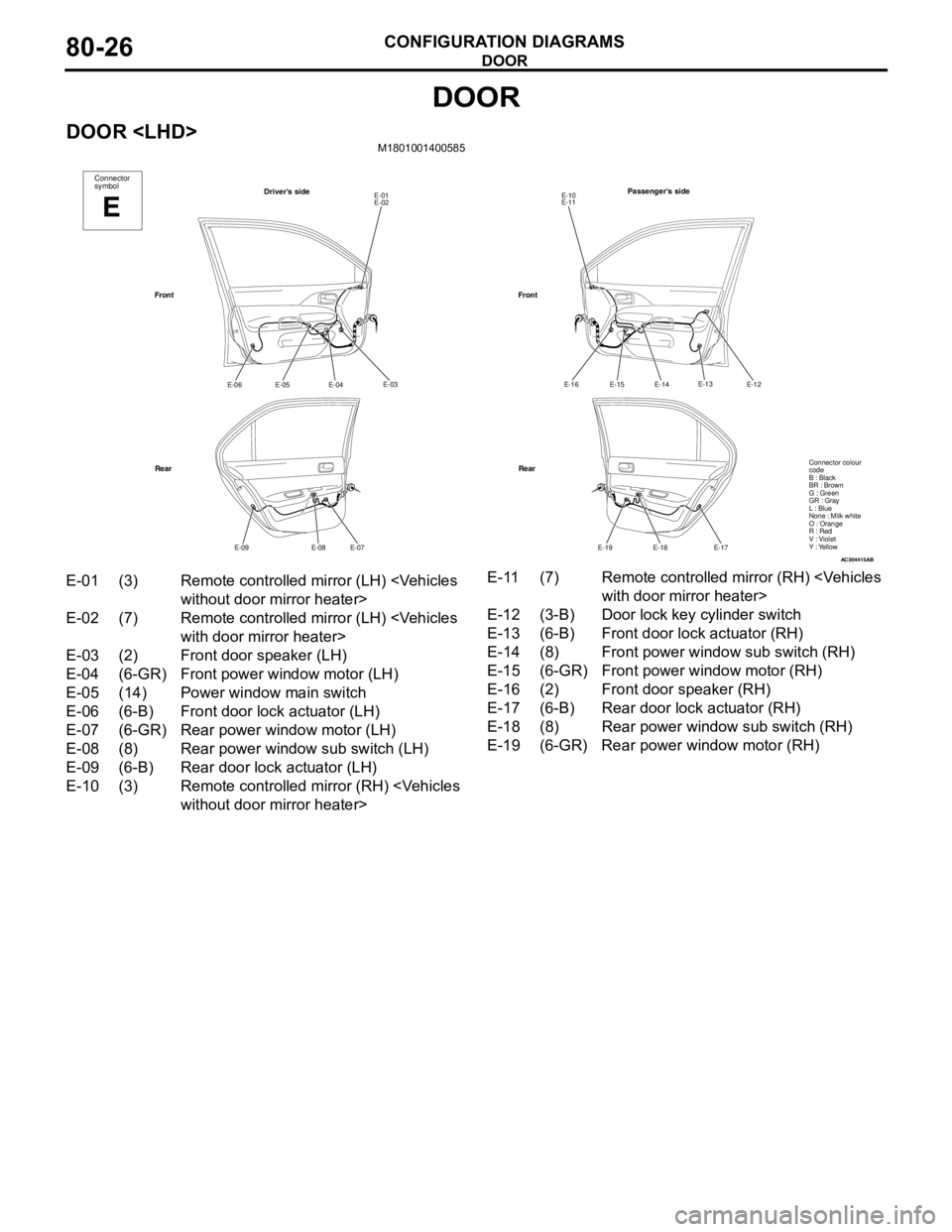
DOOR
CONFIGURATION DIAGRAMS80-26
DOOR
DOOR
AC304415
Connector
symbol
E
Driver's sideE-01
E-02
E-03
E-04
E-05 E-06
E-07
E-08 E-09
Front
RearPassenger's side
E-10
E-11
E-12
E-14
E-15 E-16
E-17
E-18 E-19
Front
Rear
AB
E-13
Connector colour
code
B : Black
BR : Brown
G : Green
GR : Gray
L : Blue
None : Milk white
O : Orange
R : Red
V : Violet
Y : Yellow
E-01 (3) Remote controlled mirror (LH)
E-02 (7) Remote controlled mirror (LH)
E-03 (2) Front door speaker (LH)
E-04 (6-GR) Front power window motor (LH)
E-05 (14) Power window main switch
E-06 (6-B) Front door lock actuator (LH)
E-07 (6-GR) Rear power window motor (LH)
E-08 (8) Rear power window sub switch (LH)
E-09 (6-B) Rear door lock actuator (LH)
E-10 (3) Remote controlled mirror (RH)
E-12 (3-B) Door lock key cylinder switch
E-13 (6-B) Front door lock actuator (RH)
E-14 (8) Front power window sub switch (RH)
E-15 (6-GR) Front power window motor (RH)
E-16 (2) Front door speaker (RH)
E-17 (6-B) Rear door lock actuator (RH)
E-18 (8) Rear power window sub switch (RH)
E-19 (6-GR) Rear power window motor (RH)
Page 633 of 788
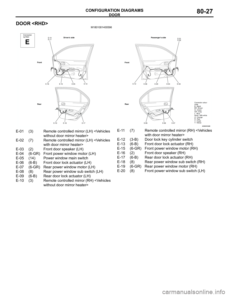
DOOR
CONFIGURATION DIAGRAMS80-27
DOOR
AC304416
Connector
symbol
E
Driver's sideE-10
E-11
E-13
E-05
E-15 E-16
E-17
E-18 E-19
Front
RearPassenger's side
E-01
E-02
E-03
E-04
E-20 E-06
E-07
E-08 E-09
Front
Rear
AB
E-12
Connector colour
code
B : Black
BR : Brown
G : Green
GR : Gray
L : Blue
None : Milk white
O : Orange
R : Red
V : Violet
Y : Yellow
E-01 (3) Remote controlled mirror (LH)
E-02 (7) Remote controlled mirror (LH)
E-03 (2) Front door speaker (LH)
E-04 (6-GR) Front power window motor (LH)
E-05 (14) Power window main switch
E-06 (6-B) Front door lock actuator (LH)
E-07 (6-GR) Rear power window motor (LH)
E-08 (8) Rear power window sub switch (LH)
E-09 (6-B) Rear door lock actuator (LH)
E-10 (3) Remote controlled mirror (RH)
E-12 (3-B) Door lock key cylinder switch
E-13 (6-B) Front door lock actuator (RH)
E-15 (6-GR) Front power window motor (RH)
E-16 (2) Front door speaker (RH)
E-17 (6-B) Rear door lock actuator (RH)
E-18 (8) Rear power window sub switch (RH)
E-19 (6-GR) Rear power window motor (RH)
E-20 (8) Front power window sub switch (LH)
Page 641 of 788

90-3
CENTRAL DOOR LOCKING SYSTEM
CENTRAL DOOR LOCKING SYSTEM
HEATER
HEATER
MANUAL AIR CONDITIONER
MANUAL AIR CONDITIONER
WINDSHIELD WIPER AND WASHER
WINDSHIELD WIPER AND WASHER
RHD> . . . . . . . . . . . . . . . . . . . . . . . . .90-121
REAR WIPER AND WASHER
REAR WIPER AND WASHER
REAR WINDOW DEFOGGER AND
DOOR MIRROR HEATER
REAR WINDOW DEFOGGER AND
DOOR MIRROR HEATER
REMOTE CONTROLLED MIRROR
HEADLAMP WASHER . . . . . . . . . . . .90-131
SPARE CONNECTOR (FOR AUDIO)
SPARE CONNECTOR (FOR AUDIO)
CLOCK . . . . . . . . . . . . . . . . . . . . . . . .90-134
CIGARETTE LIGHTER AND ASHTRAY
ILLUMINATION LAMP . . . . . . . . . . . .90-135
ACCESSORY SOCKET . . . . . . . . . . .90-136
IMMOBILIZER SYSTEM
IMMOBILIZER SYSTEM
ABS
ABS
HEATED SEAT . . . . . . . . . . . . . . . . . .90-143
RHEOSTAT
RHEOSTAT
SUPPLEMENTAL RESTRAINT SYSTEM
(SRS)
SUPPLEMENTAL RESTRAINT SYSTEM
(SRS)
SPARE CONNECTOR (FOR FRONT
FOG LAMP) . . . . . . . . . . . . . . . . . . . .90-150