check MITSUBISHI LANCER 2005 Workshop Manual
[x] Cancel search | Manufacturer: MITSUBISHI, Model Year: 2005, Model line: LANCER, Model: MITSUBISHI LANCER 2005Pages: 788, PDF Size: 45.98 MB
Page 389 of 788
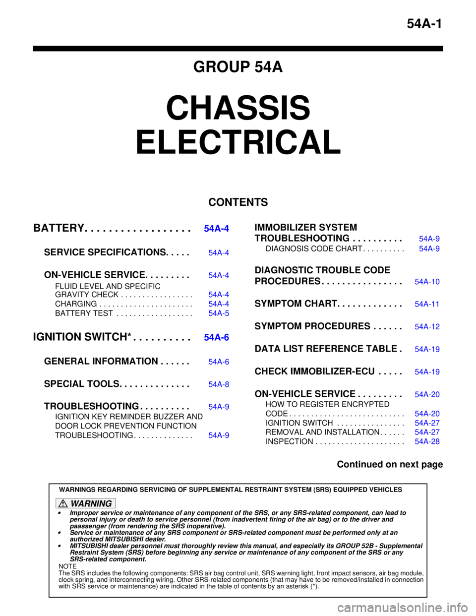
54A-1
GROUP 54A
CHASSIS
ELECTRICAL
CONTENTS
BATTERY. . . . . . . . . . . . . . . . . .
54A-4
SERVICE SPECIFICATIONS. . . . .
54A-4
ON-VEHICLE SERVICE. . . . . . . . .54A-4
FLUID LEVEL AND SPECIFIC
GRAVITY CHECK . . . . . . . . . . . . . . . . . 54A-4
CHARGING . . . . . . . . . . . . . . . . . . . . . . 54A-4
BATTERY TEST . . . . . . . . . . . . . . . . . . 54A-5
IGNITION SWITCH* . . . . . . . . . .54A-6
GENERAL INFORMATION . . . . . .
54A-6
SPECIAL TOOLS. . . . . . . . . . . . . .54A-8
TROUBLESHOOTING . . . . . . . . . .54A-9
IGNITION KEY REMINDER BUZZER AND
DOOR LOCK PREVENTION FUNCTION
TROUBLESHOOTING . . . . . . . . . . . . . . 54A-9
IMMOBILIZER SYSTEM
TROUBLESHOOTING . . . . . . . . . .
54A-9
DIAGNOSIS CODE CHART . . . . . . . . . . 54A-9
DIAGNOSTIC TROUBLE CODE
PROCEDURES . . . . . . . . . . . . . . . .
54A-10
SYMPTOM CHART. . . . . . . . . . . . .54A-11
SYMPTOM PROCEDURES . . . . . .54A-12
DATA LIST REFERENCE TABLE .54A-19
CHECK IMMOBILIZER-ECU . . . . .54A-19
ON-VEHICLE SERVICE . . . . . . . . .54A-20
HOW TO REGISTER ENCRYPTED
CODE . . . . . . . . . . . . . . . . . . . . . . . . . . . 54A-20
IGNITION SWITCH . . . . . . . . . . . . . . . . 54A-27
REMOVAL AND INSTALLATION . . . . . . 54A-27
INSPECTION . . . . . . . . . . . . . . . . . . . . . 54A-28
Continued on next page
WARNINGS REGARDING SERVICING OF SUPPLEMENTAL RESTRAINT SYSTEM (SRS) EQUIPPED VEHICLES
WARNING
•Improper service or maintenance of any component of the SRS, or any SRS-related component, can lead to
personal injury or death to service personnel (from inadvertent firing of the air bag) or to the driver and
paassenger (from rendering the SRS inoperative).
•Service or maintenance of any SRS component or SRS-related component must be performed only at an
authorized MITSUBISHI dealer.
•MITSUBISHI dealer personnel must thoroughly review this manual, and especially its GROUP 52B - Supplemental
Restraint System (SRS) before beginning any service or maintenance of any component of the SRS or any
SRS-related component.
NOTE
The SRS includes the following components: SRS air bag control unit, SRS warning light, front impact sensors, air bag module,
clock spring, and interconnecting wiring. Other SRS-related components (that may have to be removed/installed in connection
with SRS service or maintenance) are indicated in the table of contents by an asterisk (*).
Page 390 of 788
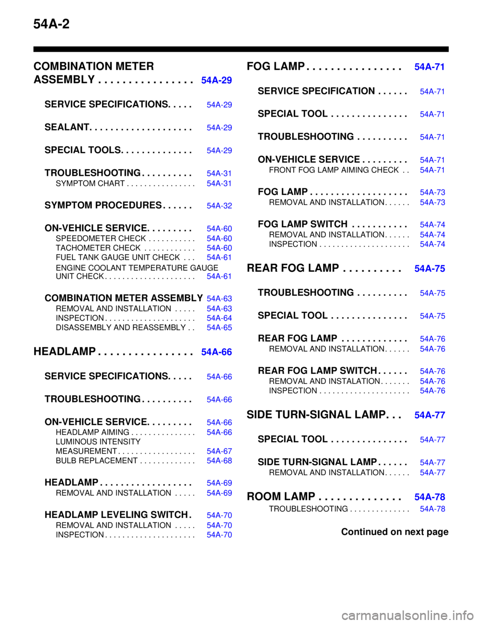
54A-2
COMBINATION METER
ASSEMBLY . . . . . . . . . . . . . . . .
54A-29
SERVICE SPECIFICATIONS. . . . .
54A-29
SEALANT. . . . . . . . . . . . . . . . . . . .54A-29
SPECIAL TOOLS. . . . . . . . . . . . . .54A-29
TROUBLESHOOTING . . . . . . . . . .54A-31
SYMPTOM CHART . . . . . . . . . . . . . . . . 54A-31
SYMPTOM PROCEDURES . . . . . .54A-32
ON-VEHICLE SERVICE. . . . . . . . .54A-60
SPEEDOMETER CHECK . . . . . . . . . . . 54A-60
TACHOMETER CHECK . . . . . . . . . . . . 54A-60
FUEL TANK GAUGE UNIT CHECK . . . 54A-61
ENGINE COOLANT TEMPERATURE GAUGE
UNIT CHECK . . . . . . . . . . . . . . . . . . . . . 54A-61
COMBINATION METER ASSEMBLY54A-63
REMOVAL AND INSTALLATION . . . . . 54A-63
INSPECTION . . . . . . . . . . . . . . . . . . . . . 54A-64
DISASSEMBLY AND REASSEMBLY . . 54A-65
HEADLAMP . . . . . . . . . . . . . . . .54A-66
SERVICE SPECIFICATIONS. . . . .
54A-66
TROUBLESHOOTING . . . . . . . . . .54A-66
ON-VEHICLE SERVICE. . . . . . . . .54A-66
HEADLAMP AIMING . . . . . . . . . . . . . . . 54A-66
LUMINOUS INTENSITY
MEASUREMENT . . . . . . . . . . . . . . . . . . 54A-67
BULB REPLACEMENT . . . . . . . . . . . . . 54A-68
HEADLAMP . . . . . . . . . . . . . . . . . .54A-69
REMOVAL AND INSTALLATION . . . . . 54A-69
HEADLAMP LEVELING SWITCH .54A-70
REMOVAL AND INSTALLATION . . . . . 54A-70
INSPECTION . . . . . . . . . . . . . . . . . . . . . 54A-70
FOG LAMP . . . . . . . . . . . . . . . . 54A-71
SERVICE SPECIFICATION . . . . . .
54A-71
SPECIAL TOOL . . . . . . . . . . . . . . .54A-71
TROUBLESHOOTING . . . . . . . . . .54A-71
ON-VEHICLE SERVICE . . . . . . . . .54A-71
FRONT FOG LAMP AIMING CHECK . . 54A-71
FOG LAMP . . . . . . . . . . . . . . . . . . .54A-73
REMOVAL AND INSTALLATION . . . . . . 54A-73
FOG LAMP SWITCH . . . . . . . . . . .54A-74
REMOVAL AND INSTALLATION . . . . . . 54A-74
INSPECTION . . . . . . . . . . . . . . . . . . . . . 54A-74
REAR FOG LAMP . . . . . . . . . . 54A-75
TROUBLESHOOTING . . . . . . . . . .
54A-75
SPECIAL TOOL . . . . . . . . . . . . . . .54A-75
REAR FOG LAMP . . . . . . . . . . . . .54A-76
REMOVAL AND INSTALLATION . . . . . . 54A-76
REAR FOG LAMP SWITCH . . . . . .54A-76
REMOVAL AND INSTALATION . . . . . . . 54A-76
INSPECTION . . . . . . . . . . . . . . . . . . . . . 54A-76
SIDE TURN-SIGNAL LAMP. . . 54A-77
SPECIAL TOOL . . . . . . . . . . . . . . .
54A-77
SIDE TURN-SIGNAL LAMP . . . . . .54A-77
REMOVAL AND INSTALLATION . . . . . . 54A-77
ROOM LAMP . . . . . . . . . . . . . . 54A-78
TROUBLESHOOTING . . . . . . . . . . . . . . 54A-78
Continued on next page
Page 391 of 788
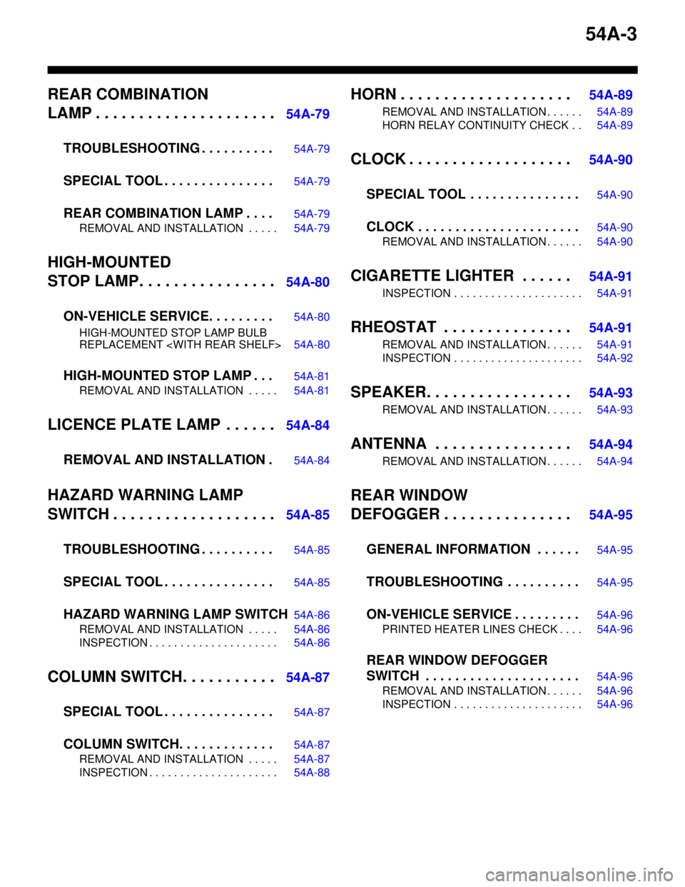
54A-3
REAR COMBINATION
LAMP . . . . . . . . . . . . . . . . . . . . .
54A-79
TROUBLESHOOTING . . . . . . . . . .
54A-79
SPECIAL TOOL . . . . . . . . . . . . . . .54A-79
REAR COMBINATION LAMP . . . .54A-79
REMOVAL AND INSTALLATION . . . . . 54A-79
HIGH-MOUNTED
STOP LAMP. . . . . . . . . . . . . . . .
54A-80
ON-VEHICLE SERVICE. . . . . . . . .
54A-80
HIGH-MOUNTED STOP LAMP BULB
REPLACEMENT
HIGH-MOUNTED STOP LAMP . . .54A-81
REMOVAL AND INSTALLATION . . . . . 54A-81
LICENCE PLATE LAMP . . . . . .54A-84
REMOVAL AND INSTALLATION .
54A-84
HAZARD WARNING LAMP
SWITCH . . . . . . . . . . . . . . . . . . .
54A-85
TROUBLESHOOTING . . . . . . . . . .
54A-85
SPECIAL TOOL . . . . . . . . . . . . . . .54A-85
HAZARD WARNING LAMP SWITCH54A-86
REMOVAL AND INSTALLATION . . . . . 54A-86
INSPECTION . . . . . . . . . . . . . . . . . . . . . 54A-86
COLUMN SWITCH. . . . . . . . . . .54A-87
SPECIAL TOOL . . . . . . . . . . . . . . .
54A-87
COLUMN SWITCH. . . . . . . . . . . . .54A-87
REMOVAL AND INSTALLATION . . . . . 54A-87
INSPECTION . . . . . . . . . . . . . . . . . . . . . 54A-88
HORN . . . . . . . . . . . . . . . . . . . . 54A-89
REMOVAL AND INSTALLATION . . . . . . 54A-89
HORN RELAY CONTINUITY CHECK . . 54A-89
CLOCK . . . . . . . . . . . . . . . . . . . 54A-90
SPECIAL TOOL . . . . . . . . . . . . . . .
54A-90
CLOCK . . . . . . . . . . . . . . . . . . . . . .54A-90
REMOVAL AND INSTALLATION . . . . . . 54A-90
CIGARETTE LIGHTER . . . . . . 54A-91
INSPECTION . . . . . . . . . . . . . . . . . . . . . 54A-91
RHEOSTAT . . . . . . . . . . . . . . . 54A-91
REMOVAL AND INSTALLATION . . . . . . 54A-91
INSPECTION . . . . . . . . . . . . . . . . . . . . . 54A-92
SPEAKER. . . . . . . . . . . . . . . . . 54A-93
REMOVAL AND INSTALLATION . . . . . . 54A-93
ANTENNA . . . . . . . . . . . . . . . . 54A-94
REMOVAL AND INSTALLATION . . . . . . 54A-94
REAR WINDOW
DEFOGGER . . . . . . . . . . . . . . .
54A-95
GENERAL INFORMATION . . . . . .
54A-95
TROUBLESHOOTING . . . . . . . . . .54A-95
ON-VEHICLE SERVICE . . . . . . . . .54A-96
PRINTED HEATER LINES CHECK . . . . 54A-96
REAR WINDOW DEFOGGER
SWITCH . . . . . . . . . . . . . . . . . . . . .
54A-96
REMOVAL AND INSTALLATION . . . . . . 54A-96
INSPECTION . . . . . . . . . . . . . . . . . . . . . 54A-96
Page 392 of 788
BATTERY
CHASSIS ELECTRICAL54A-4
BATTERY
SERVICE SPECIFICATIONSM1541000300209
ON-VEHICLE SERVICE
FLUID LEVEL AND SPECIFIC GRAVITY
CHECK
M1541001000438
CAUTION
•If the battery fluid is below the LOWER
LEVEL, the battery could explode in using.
•If the battery fluid is over the UPPER LEVEL,
leakage could result.
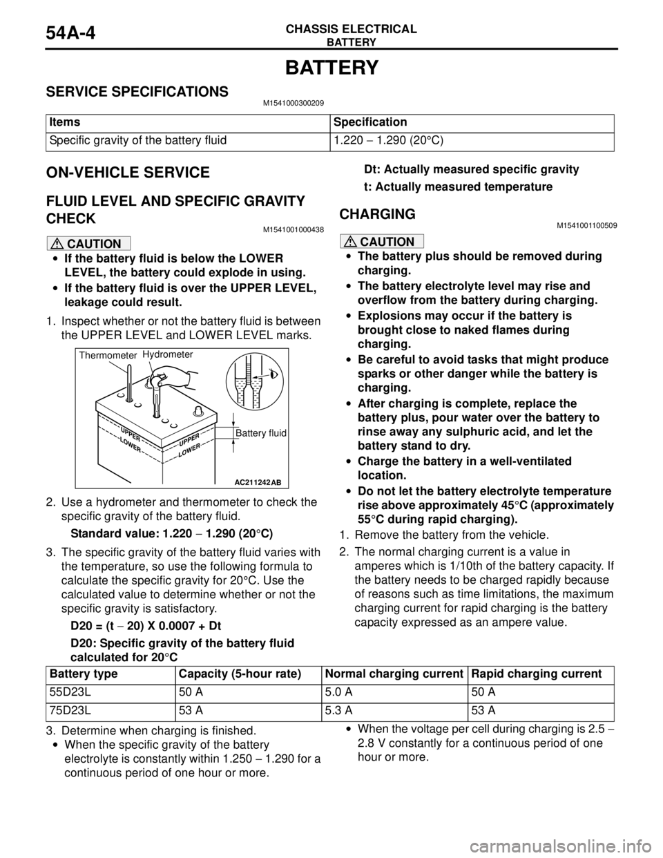
1. Inspect whether or not the battery fluid is between
the UPPER LEVEL and LOWER LEVEL marks.
2. Use a hydrometer and thermometer to check the
specific gravity of the battery fluid.
Standard value: 1.220 − 1.290 (20°C)
3. The specific gravity of the battery fluid varies with
the temperature, so use the following formula to
calculate the specific gravity for 20°C. Use the
calculated value to determine whether or not the
specific gravity is satisfactory.
D20 = (t − 20) X 0.0007 + Dt
D20: Specific gravity of the battery fluid
calculated for 20°CDt: Actually measured specific gravity
t: Actually measured temperature
CHARGINGM1541001100509
CAUTION
•The battery plus should be removed during
charging.
•The battery electrolyte level may rise and
overflow from the battery during charging.
•Explosions may occur if the battery is
brought close to naked flames during
charging.
•Be careful to avoid tasks that might produce
sparks or other danger while the battery is
charging.
•After charging is complete, replace the
battery plus, pour water over the battery to
rinse away any sulphuric acid, and let the
battery stand to dry.
•Charge the battery in a well-ventilated
location.
•Do not let the battery electrolyte temperature
rise above approximately 45°C (approximately
55°C during rapid charging).
1. Remove the battery from the vehicle.
2. The normal charging current is a value in
amperes which is 1/10th of the battery capacity. If
the battery needs to be charged rapidly because
of reasons such as time limitations, the maximum
charging current for rapid charging is the battery
capacity expressed as an ampere value.
3. Determine when charging is finished.
•When the specific gravity of the battery
electrolyte is constantly within 1.250 − 1.290 for a
continuous period of one hour or more.•When the voltage per cell during charging is 2.5 −
2.8 V constantly for a continuous period of one
hour or more. Items Specification
Specific gravity of the battery fluid 1.220 − 1.290 (20°C)
AC211242AB
Battery fluid ThermometerHydrometer
Battery type Capacity (5-hour rate) Normal charging current Rapid charging current
55D23L 50 A 5.0 A 50 A
75D23L 53 A 5.3 A 53 A
Page 393 of 788
BATTERY
CHASSIS ELECTRICAL54A-5
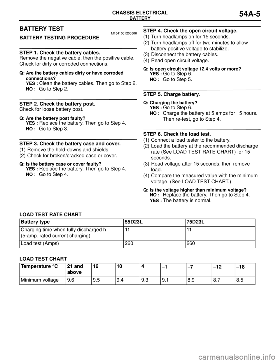
BATTERY TESTM1541001200506
BATTERY TESTING PROCEDURE
STEP 1. Check the battery cables.
Remove the negative cable, then the positive cable.
Check for dirty or corroded connections.
Q: Are the battery cables dirty or have corroded
connections?
YES :
Clean the battery cables. Then go to Step 2.
NO : Go to Step 2.
STEP 2. Check the battery post.
Check for loose battery post.
Q: Are the battery post faulty?
YES :
Replace the battery. Then go to Step 4.
NO : Go to Step 3.
STEP 3. Check the battery case and cover.
(1) Remove the hold-downs and shields.
(2) Check for broken/cracked case or cover.
Q: Is the battery case or cover faulty?
YES :
Replace the battery. Then go to Step 4.
NO : Go to Step 4.
STEP 4. Check the open circuit voltage.
(1) Turn headlamps on for 15 seconds.
(2) Turn headlamps off for two minutes to allow
battery positive voltage to stabilize.
(3) Disconnect the battery cables.
(4) Read open circuit voltage.
Q: Is open circuit voltage 12.4 volts or more?
YES :
Go to Step 6.
NO : Go to Step 5.
STEP 5. Charge battery.
Q: Charging the battery?
YES :
Go to Step 6.
NO : Charge the battery at 5 amps for 15 hours.
Then re-test, go to Step 4.
STEP 6. Check the load test.
(1) Connect a load tester to the battery.
(2) Load the battery at the recommended discharge
rate (See LOAD TEST RATE CHART) for 15
seconds.
(3) Read voltage after 15 seconds, then remove
load.
(4) Compare the measured value with the minimum
voltage. (See LOAD TEST CHART.)
Q: Is the voltage higher than minimum voltage?
NO :
Replace the battery. Then go to Step 4.
YES : The battery is normal.
LOAD TEST RATE CHART
LOAD TEST CHARTBattery type 55D23L 75D23L
Charging time when fully discharged h
(5-amp. rated current charging)11 11
Load test (Amps) 260 260
Temperature °C 21 and
above16 10 4
−1−7−12−18
Minimum voltage 9.6 9.5 9.4 9.3 9.1 8.9 8.7 8.5
Page 396 of 788
IGNITION SWITCH
CHASSIS ELECTRICAL54A-8
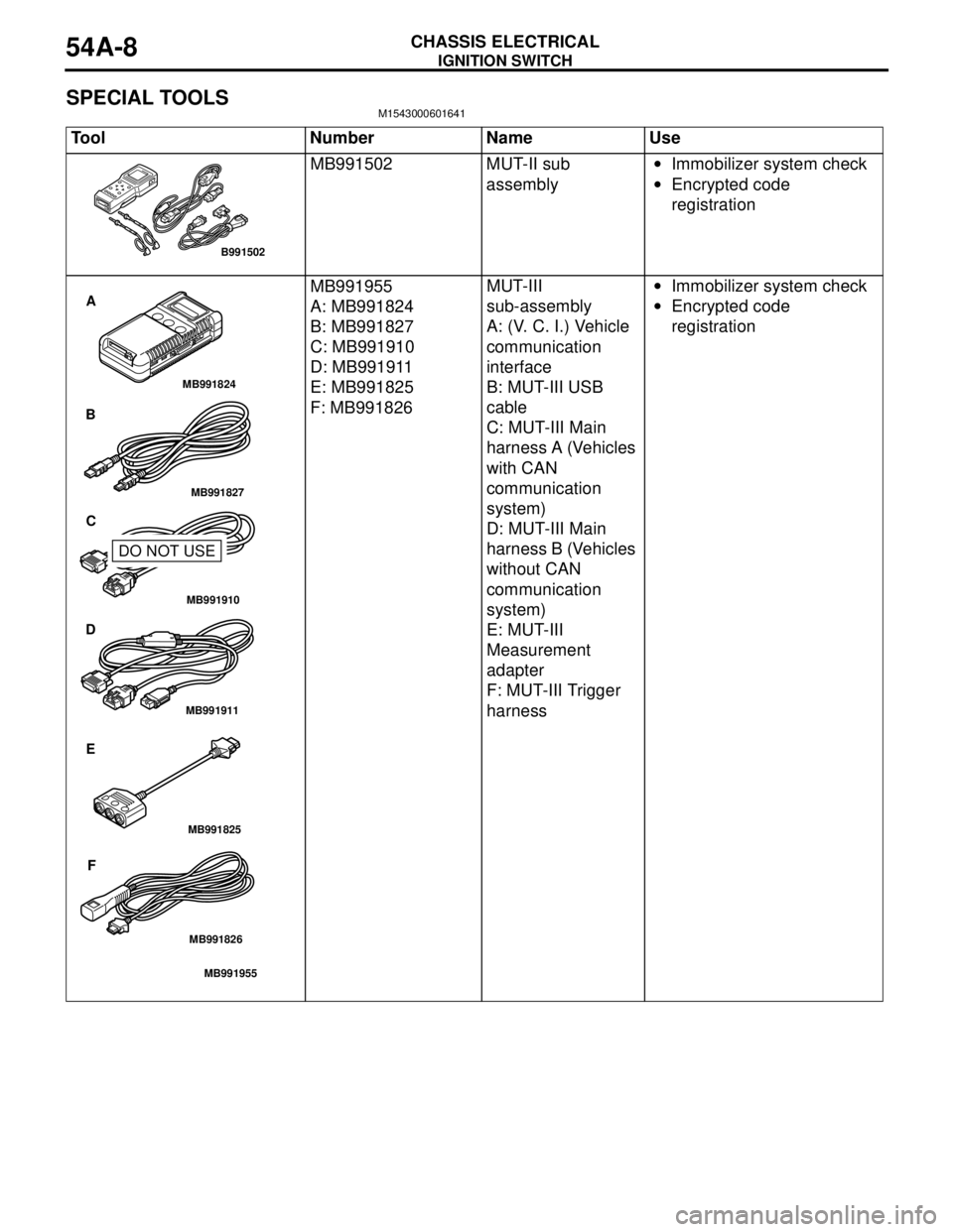
SPECIAL TOOLSM1543000601641
Tool Number Name Use
MB991502 MUT-II sub
assembly•Immobilizer system check
•Encrypted code
registration
MB991955
A: MB991824
B: MB991827
C: MB991910
D: MB991911
E: MB991825
F: MB991826MUT-III
sub-assembly
A: (V. C. I.) Vehicle
communication
interface
B: MUT-III USB
cable
C: MUT-III Main
harness A (Vehicles
with CAN
communication
system)
D: MUT-III Main
harness B (Vehicles
without CAN
communication
system)
E: MUT-III
Measurement
adapter
F: MUT-III Trigger
harness•Immobilizer system check
•Encrypted code
registration
B991502
MB991910
MB991826
MB991955
MB991911
MB991824
MB991827
MB991825
A
B
C
D
E
F
DO NOT USE
Page 399 of 788
IGNITION SWITCH
CHASSIS ELECTRICAL54A-11
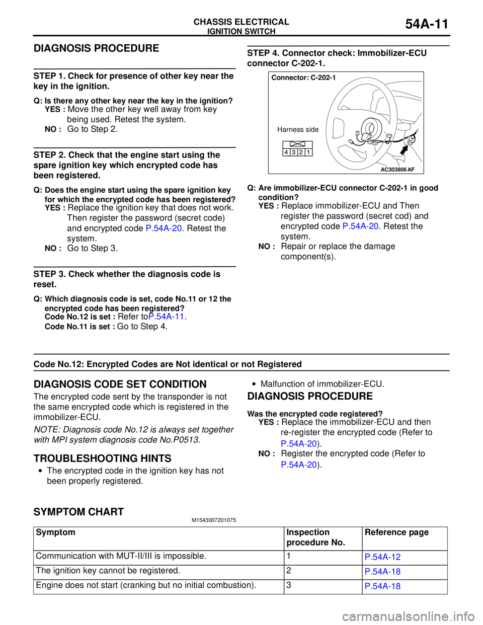
DIAGNOSIS PROCEDURE
STEP 1. Check for presence of other key near the
key in the ignition.
Q: Is there any other key near the key in the ignition?
YES :
Move the other key well away from key
being used. Retest the system.
NO : Go to Step 2.
STEP 2. Check that the engine start using the
spare ignition key which encrypted code has
been registered.
Q: Does the engine start using the spare ignition key
for which the encrypted code has been registered?
YES :
Replace the ignition key that does not work.
Then register the password (secret code)
and encrypted code P.54A-20. Retest the
system.
NO : Go to Step 3.
STEP 3. Check whether the diagnosis code is
reset.
Q: Which diagnosis code is set, code No.11 or 12 the
encrypted code has been registered?
Code No.12 is set :
Refer toP.54A-11.
Code No.11 is set : Go to Step 4.
STEP 4. Connector check: Immobilizer-ECU
connector C-202-1.
Q: Are immobilizer-ECU connector C-202-1 in good
condition?
YES :
Replace immobilizer-ECU and Then
register the password (secret cod) and
encrypted code P.54A-20. Retest the
system.
NO : Repair or replace the damage
component(s).
Code No.12: Encrypted Codes are Not identical or not Registered
DIAGNOSIS CODE SET CONDITION
The encrypted code sent by the transponder is not
the same encrypted code which is registered in the
immobilizer-ECU.
NOTE: Diagnosis code No.12 is always set together
with MPI system diagnosis code No.P0513.
TROUBLESHOOTING HINTS
•The encrypted code in the ignition key has not
been properly registered.•Malfunction of immobilizer-ECU.
DIAGNOSIS PROCEDURE
Was the encrypted code registered?
YES :
Replace the immobilizer-ECU and then
re-register the encrypted code (Refer to
P.54A-20).
NO : Register the encrypted code (Refer to
P.54A-20).
SYMPTOM CHARTM1543007201075
AC303806
Connector: C-202-1
Harness side
AF
Symptom Inspection
procedure No.Reference page
Communication with MUT-II/III is impossible. 1
P.54A-12
The ignition key cannot be registered. 2
P.54A-18
Engine does not start (cranking but no initial combustion). 3
P.54A-18
Page 401 of 788
IGNITION SWITCH
CHASSIS ELECTRICAL54A-13
TROUBLESHOOTING HINTS
•Malfunction of the immobilizer-ECU.
•Malfunction of the engine-ECU
engine-A/T-ECU .
•The wiring harness or connectors may have
loose, corroded, or damaged terminals, or
terminals pushed back in the connector.
DIAGNOSIS PROCEDURE
STEP 1. Check if MUT-II/III can communicate with
the MPI system and if an MPI system diagnosis
code other than P0513 is set.
Q: Can MUT-II/III communicate with the MPI system?
Is an MPI system diagnosis code other than P0513
set?
YES :
Go to Step 2.
NO : Refer to GROUP 13A, MPI Diagnosis
P.13A-15, GROUP 13B, MPI Diagnosis
P.13B-15.
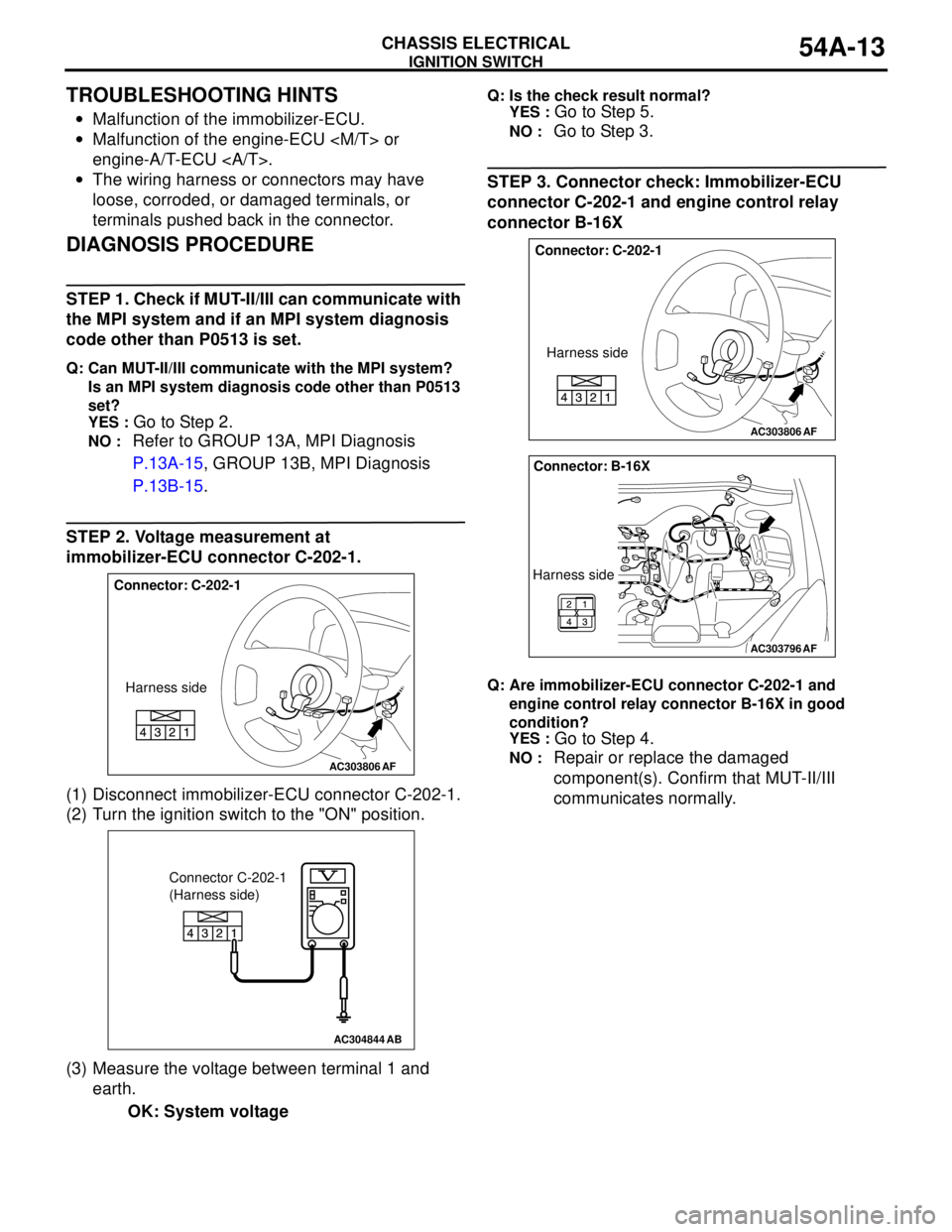
STEP 2. Voltage measurement at
immobilizer-ECU connector C-202-1.
(1) Disconnect immobilizer-ECU connector C-202-1.
(2) Turn the ignition switch to the "ON" position.
(3) Measure the voltage between terminal 1 and
earth.
OK: System voltage
Q: Is the check result normal?
YES :
Go to Step 5.
NO : Go to Step 3.
STEP 3. Connector check: Immobilizer-ECU
connector C-202-1 and engine control relay
connector B-16X
Q: Are immobilizer-ECU connector C-202-1 and
engine control relay connector B-16X in good
condition?
YES :
Go to Step 4.
NO : Repair or replace the damaged
component(s). Confirm that MUT-II/III
communicates normally.AC303806
Connector: C-202-1
Harness side
AF
AC304844AB
Connector C-202-1
(Harness side)
AC303806
Connector: C-202-1
Harness side
AF
AC303796
Connector: B-16X
Harness side
AF
Page 402 of 788
IGNITION SWITCH
CHASSIS ELECTRICAL54A-14
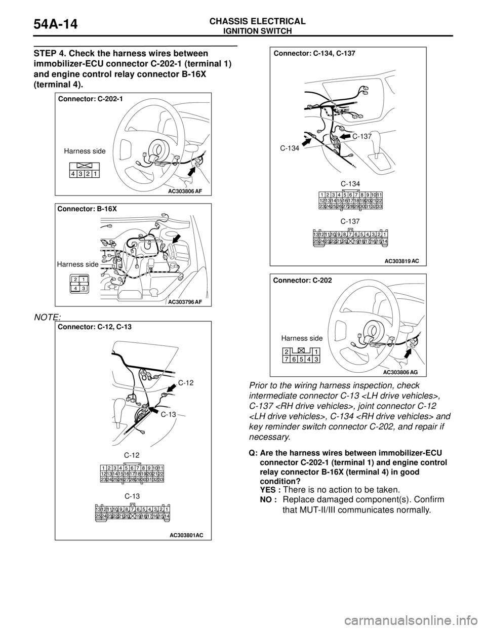
STEP 4. Check the harness wires between
immobilizer-ECU connector C-202-1 (terminal 1)
and engine control relay connector B-16X
(terminal 4).
NOTE:
Prior to the wiring harness inspection, check
intermediate connector C-13
C-137
key reminder switch connector C-202, and repair if
necessary.
Q: Are the harness wires between immobilizer-ECU
connector C-202-1 (terminal 1) and engine control
relay connector B-16X (terminal 4) in good
condition?
YES :
There is no action to be taken.
NO : Replace damaged component(s). Confirm
that MUT-II/III communicates normally.
AC303806
Connector: C-202-1
Harness side
AF
AC303796
Connector: B-16X
Harness side
AF
AC303801
Connector: C-12, C-13
C-12
C-13
C-12
C-13
AC
AC303819
Connector: C-134, C-137
C-134
C-137
C-134
C-137
AC
AC303806
Connector: C-202
Harness side
AG
Page 403 of 788
IGNITION SWITCH
CHASSIS ELECTRICAL54A-15
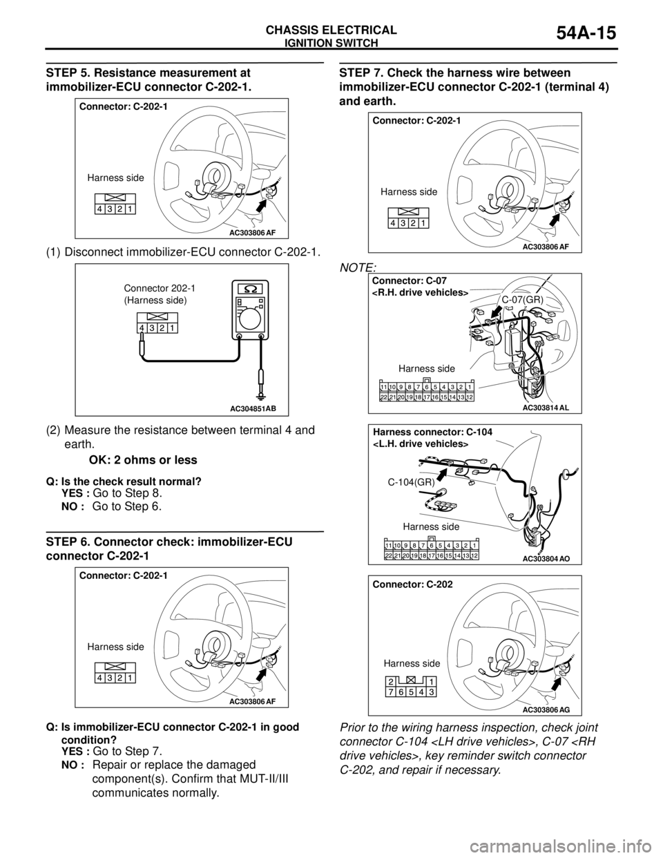
STEP 5. Resistance measurement at
immobilizer-ECU connector C-202-1.
(1) Disconnect immobilizer-ECU connector C-202-1.
(2) Measure the resistance between terminal 4 and
earth.
OK: 2 ohms or less
Q: Is the check result normal?
YES :
Go to Step 8.
NO : Go to Step 6.
STEP 6. Connector check: immobilizer-ECU
connector C-202-1
Q: Is immobilizer-ECU connector C-202-1 in good
condition?
YES :
Go to Step 7.
NO : Repair or replace the damaged
component(s). Confirm that MUT-II/III
communicates normally.
STEP 7. Check the harness wire between
immobilizer-ECU connector C-202-1 (terminal 4)
and earth.
NOTE:
Prior to the wiring harness inspection, check joint
connector C-104
C-202, and repair if necessary.
AC303806
Connector: C-202-1
Harness side
AF
AC304851AB
Connector 202-1
(Harness side)
AC303806
Connector: C-202-1
Harness side
AF
AC303806
Connector: C-202-1
Harness side
AF
AC303814
Connector: C-07
C-07(GR)
Harness side
AL
AC303804AO
Harness connector: C-104
C-104(GR)
Harness side
AC303806
Connector: C-202
Harness side
AG