check MITSUBISHI LANCER 2005 Workshop Manual
[x] Cancel search | Manufacturer: MITSUBISHI, Model Year: 2005, Model line: LANCER, Model: MITSUBISHI LANCER 2005Pages: 788, PDF Size: 45.98 MB
Page 369 of 788
REAR WIPER AND WASHER
EXTERIOR51-31
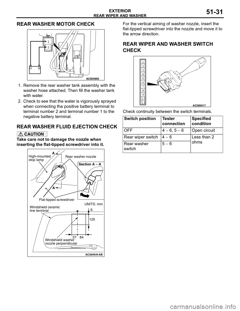
REAR WASHER MOTOR CHECK
1. Remove the rear washer tank assembly with the
washer hose attached. Then fill the washer tank
with water.
2. Check to see that the water is vigorously sprayed
when connecting the positive battery terminal to
terminal number 2 and terminal number 1 to the
negative battery terminal.
REAR WASHER FLUID EJECTION CHECK
CAUTION
Take care not to damage the nozzle when
inserting the flat-tipped screwdriver into it.For the vertical aiming of washer nozzle, insert the
flat-tipped screwdriver into the nozzle and move it to
the arrow direction.
REAR WIPER AND WASHER SWITCH
CHECK
Check continuity between the switch terminals.
1
2
AC005900
AC304544AB
UNITS: mm
57 841256 Section A – A
A A
High-mounted
stop lampRear washer nozzle
Flat-tipped screwdriverWindshield ceramic
line terminal
Windshield washer
nozzle perpendicular
Switch position Tester
connectionSpecified
condition
OFF 4 − 6, 5 − 6 Open circuit
Rear wiper switch 4 − 6 Less than 2
ohms
Rear washer
switch5 − 6
1
6
8
11 109 7
5 4
3
2
AC000417
Page 371 of 788
HEADLAMP WASHER
EXTERIOR51-33
INSPECTIONM1511009800082
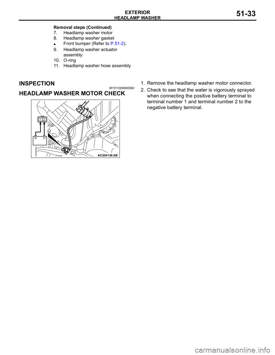
HEADLAMP WASHER MOTOR CHECK
1. Remove the headlamp washer motor connector.
2. Check to see that the water is vigorously sprayed
when connecting the positive battery terminal to
terminal number 1 and terminal number 2 to the
negative battery terminal.
7. Headlamp washer motor
8. Headlamp washer gasket
•Front bumper (Refer to P.51-2).
9. Headlamp washer actuator
assembly
10. O-ring
11. Headlamp washer hose assembly Removal steps (Continued)
AC304136AB
12
Page 376 of 788
DOOR MIRROR
EXTERIOR51-38
COMMENTS ON TROUBLE SYMPTOM
The heated door mirrors should works for
approximately 11 minutes when the rear defogger
switch is turned on. If the mirror heater does not work
for the specified period, the defogger relay circuit
(heated door mirror power supply circuit) may be
defective.
Possible causes
•Damaged harness wires and connectors
DIAGNOSIS PROCEDURE
STEP 1. Check the rear window defogger.
Check that the rear window defogger system should
work normally.
Q: Is the check result normal?
YES :
Go to Step 2.
NO : Troubleshoot the rear window defogger
(Refer to GROUP 55,
TroubleshootingP.55-42).
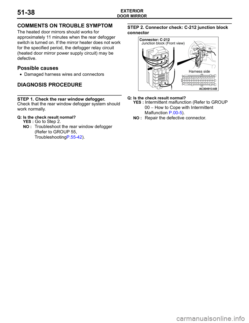
STEP 2. Connector check: C-212 junction block
connector
Q: Is the check result normal?
YES :
Intermittent malfunction (Refer to GROUP
00 − How to Cope with Intermittent
Malfunction P.00-5).
NO : Repair the defective connector.
AC304913
21716151718 201912345 623 222425282627981011141213
Connector: C-212
Harness side
AB
Junction block (Front view)
Page 378 of 788
DOOR MIRROR
EXTERIOR51-40
COMMENTS ON TROUBLE SYMPTOM
If either of the heated door mirrors does not work, the
door mirror assembly may be defective.
Possible causes
•Malfunction of the door mirror assembly
•Damaged harness wires and connectors
DIAGNOSIS PROCEDURE
Step 1. Verify the operation of each heated door
mirror.
Q: Which door mirror does not heat?
Door mirror (RH) :
Go to Step 2.
Door mirror (LH) : Go to Step 9.
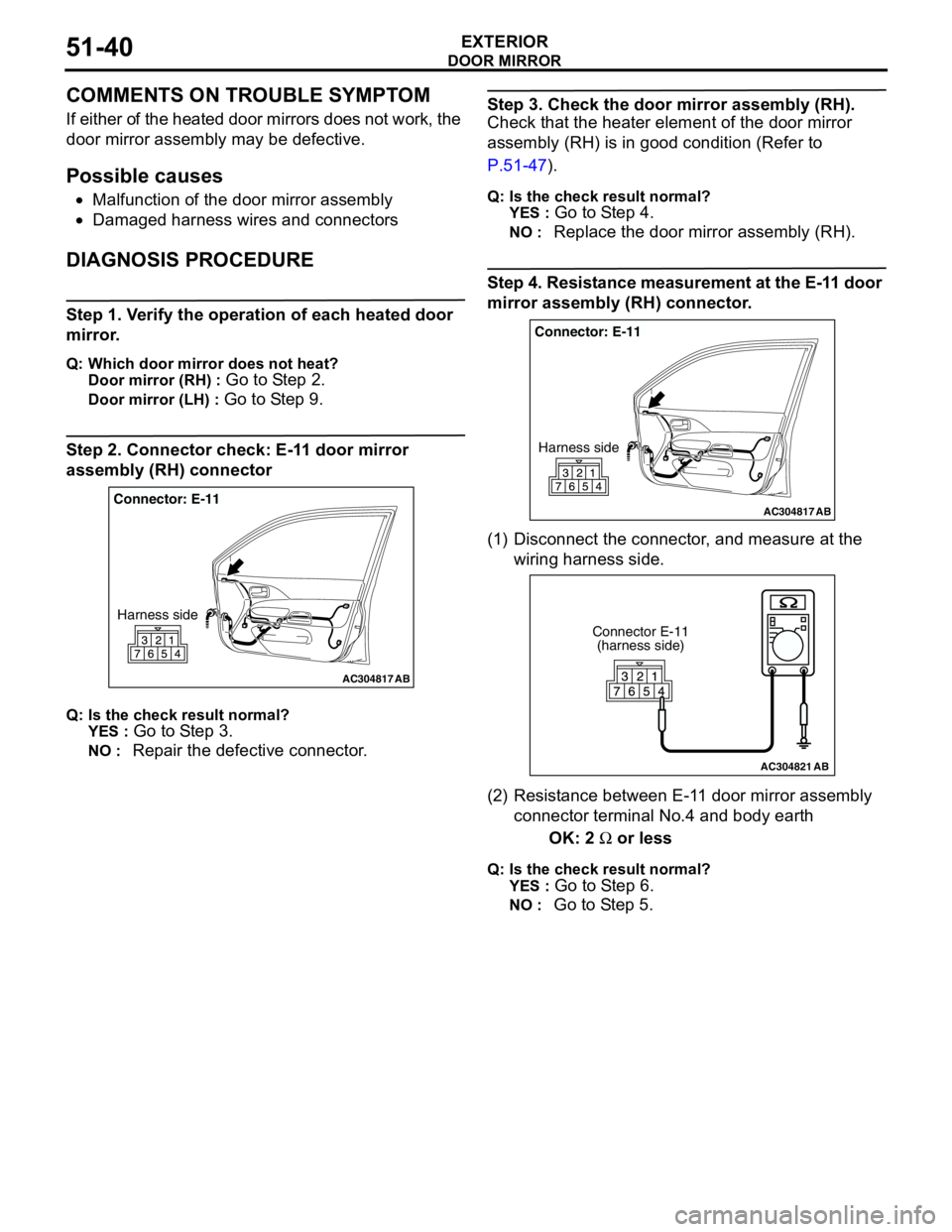
Step 2. Connector check: E-11 door mirror
assembly (RH) connector
Q: Is the check result normal?
YES :
Go to Step 3.
NO : Repair the defective connector.
Step 3. Check the door mirror assembly (RH).
Check that the heater element of the door mirror
assembly (RH) is in good condition (Refer to
P.51-47).
Q: Is the check result normal?
YES :
Go to Step 4.
NO : Replace the door mirror assembly (RH).
Step 4. Resistance measurement at the E-11 door
mirror assembly (RH) connector.
(1) Disconnect the connector, and measure at the
wiring harness side.
(2) Resistance between E-11 door mirror assembly
connector terminal No.4 and body earth
OK: 2 Ω or less
Q: Is the check result normal?
YES :
Go to Step 6.
NO : Go to Step 5.
AC304817
Connector: E-11
Harness side
AB
AC304817
Connector: E-11
Harness side
AB
AC304821
Connector E-11
(harness side)
AB
Page 379 of 788
DOOR MIRROR
EXTERIOR51-41
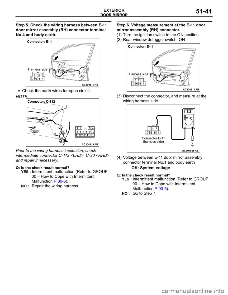
Step 5. Check the wiring harness between E-11
door mirror assembly (RH) connector terminal
No.4 and body earth.
•Check the earth wires for open circuit.
NOTE:
Prior to the wiring harness inspection, check
intermediate connector C-112
and repair if necessary.
Q: Is the check result normal?
YES :
Intermittent malfunction (Refer to GROUP
00 − How to Cope with Intermittent
Malfunction P.00-5).
NO : Repair the wiring harness.
Step 6. Voltage measurement at the E-11 door
mirror assembly (RH) connector.
(1) Turn the ignition switch to the ON position.
(2) Rear window defogger switch: ON
(3) Disconnect the connector, and measure at the
wiring harness side.
(4) Voltage between E-11 door mirror assembly
connector terminal No.1 and body earth
OK: System voltage
Q: Is the check result normal?
YES :
Intermittent malfunction (Refer to GROUP
00 − How to Cope with Intermittent
Malfunction P.00-5).
NO : Go to Step 7.
AC304817
Connector: E-11
Harness side
AB
AC304819
Connector: C-112
AB
AC304817
Connector: E-11
Harness side
AB
AC304826
Connector E-11
(harness side)
AB
Page 380 of 788
DOOR MIRROR
EXTERIOR51-42
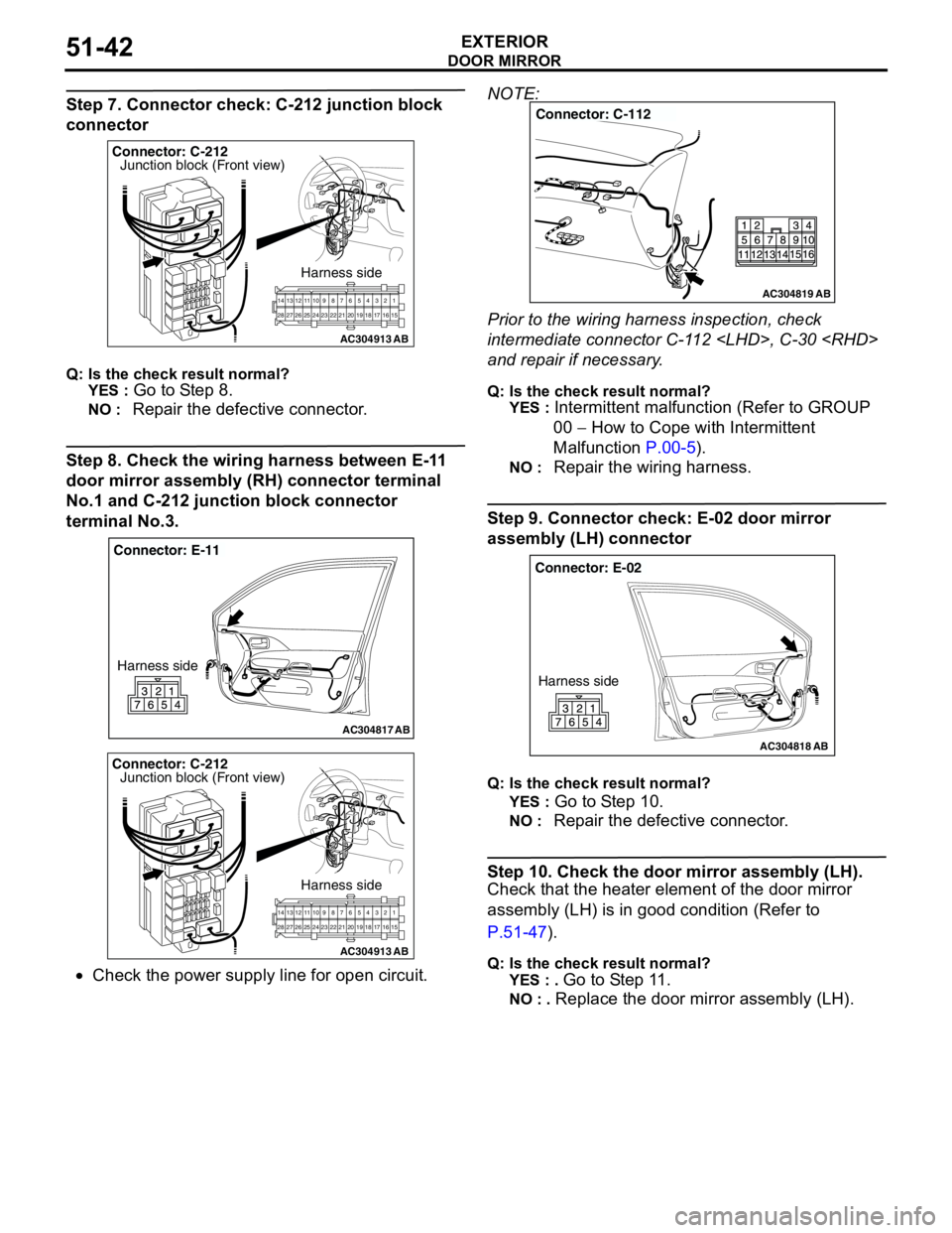
Step 7. Connector check: C-212 junction block
connector
Q: Is the check result normal?
YES :
Go to Step 8.
NO : Repair the defective connector.
Step 8. Check the wiring harness between E-11
door mirror assembly (RH) connector terminal
No.1 and C-212 junction block connector
terminal No.3.
•Check the power supply line for open circuit.NOTE:
Prior to the wiring harness inspection, check
intermediate connector C-112
and repair if necessary.
Q: Is the check result normal?
YES :
Intermittent malfunction (Refer to GROUP
00 − How to Cope with Intermittent
Malfunction P.00-5).
NO : Repair the wiring harness.
Step 9. Connector check: E-02 door mirror
assembly (LH) connector
Q: Is the check result normal?
YES :
Go to Step 10.
NO : Repair the defective connector.
Step 10. Check the door mirror assembly (LH).
Check that the heater element of the door mirror
assembly (LH) is in good condition (Refer to
P.51-47).
Q: Is the check result normal?
YES : .
Go to Step 11.
NO : . Replace the door mirror assembly (LH).
AC304913
21716151718 201912345 623 222425282627981011141213
Connector: C-212
Harness side
AB
Junction block (Front view)
AC304817
Connector: E-11
Harness side
AB
AC304913
21716151718 201912345 623 222425282627981011141213
Connector: C-212
Harness side
AB
Junction block (Front view)
AC304819
Connector: C-112
AB
AC304818
Connector: E-02
Harness side
AB
Page 381 of 788
DOOR MIRROR
EXTERIOR51-43
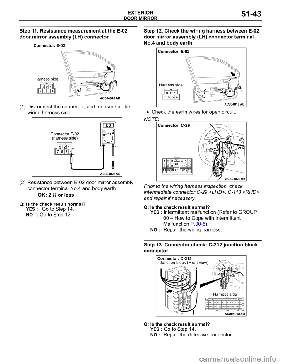
Step 11. Resistance measurement at the E-02
door mirror assembly (LH) connector.
(1) Disconnect the connector, and measure at the
wiring harness side.
(2) Resistance between E-02 door mirror assembly
connector terminal No.4 and body earth
OK: 2 Ω or less
Q: Is the check result normal?
YES : .
Go to Step 14.
NO : . Go to Step 12.
Step 12. Check the wiring harness between E-02
door mirror assembly (LH) connector terminal
No.4 and body earth.
•Check the earth wires for open circuit.
NOTE:
Prior to the wiring harness inspection, check
intermediate connector C-29
and repair if necessary.
Q: Is the check result normal?
YES :
Intermittent malfunction (Refer to GROUP
00 − How to Cope with Intermittent
Malfunction P.00-5).
NO : Repair the wiring harness.
Step 13. Connector check: C-212 junction block
connector
Q: Is the check result normal?
YES :
Go to Step 14.
NO : Repair the defective connector.
AC304818
Connector: E-02
Harness side
AB
AC304827
Connector E-02
(harness side)
AB
AC304818
Connector: E-02
Harness side
AB
AC304820
Connector: C-29
AB
AC304913
21716151718 201912345 623 222425282627981011141213
Connector: C-212
Harness side
AB
Junction block (Front view)
Page 382 of 788
DOOR MIRROR
EXTERIOR51-44
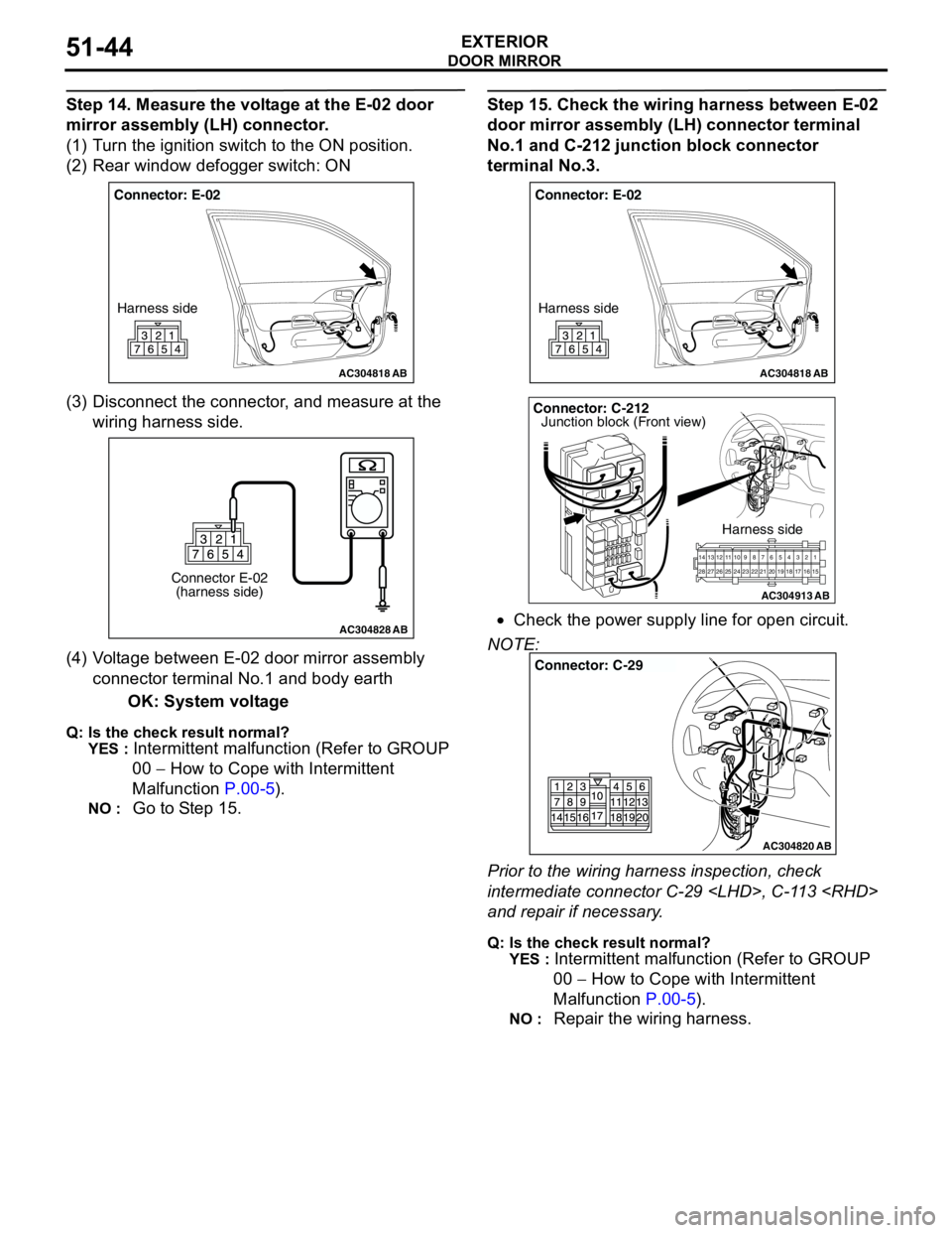
Step 14. Measure the voltage at the E-02 door
mirror assembly (LH) connector.
(1) Turn the ignition switch to the ON position.
(2) Rear window defogger switch: ON
(3) Disconnect the connector, and measure at the
wiring harness side.
(4) Voltage between E-02 door mirror assembly
connector terminal No.1 and body earth
OK: System voltage
Q: Is the check result normal?
YES :
Intermittent malfunction (Refer to GROUP
00 − How to Cope with Intermittent
Malfunction P.00-5).
NO : Go to Step 15.
Step 15. Check the wiring harness between E-02
door mirror assembly (LH) connector terminal
No.1 and C-212 junction block connector
terminal No.3.
•Check the power supply line for open circuit.
NOTE:
Prior to the wiring harness inspection, check
intermediate connector C-29
and repair if necessary.
Q: Is the check result normal?
YES :
Intermittent malfunction (Refer to GROUP
00 − How to Cope with Intermittent
Malfunction P.00-5).
NO : Repair the wiring harness.
AC304818
Connector: E-02
Harness side
AB
AC304828
Connector E-02
(harness side)
AB
AC304818
Connector: E-02
Harness side
AB
AC304913
21716151718 201912345 623 222425282627981011141213
Connector: C-212
Harness side
AB
Junction block (Front view)
AC304820
Connector: C-29
AB
Page 385 of 788
DOOR MIRROR
EXTERIOR51-47
INSPECTIONM1511006500286
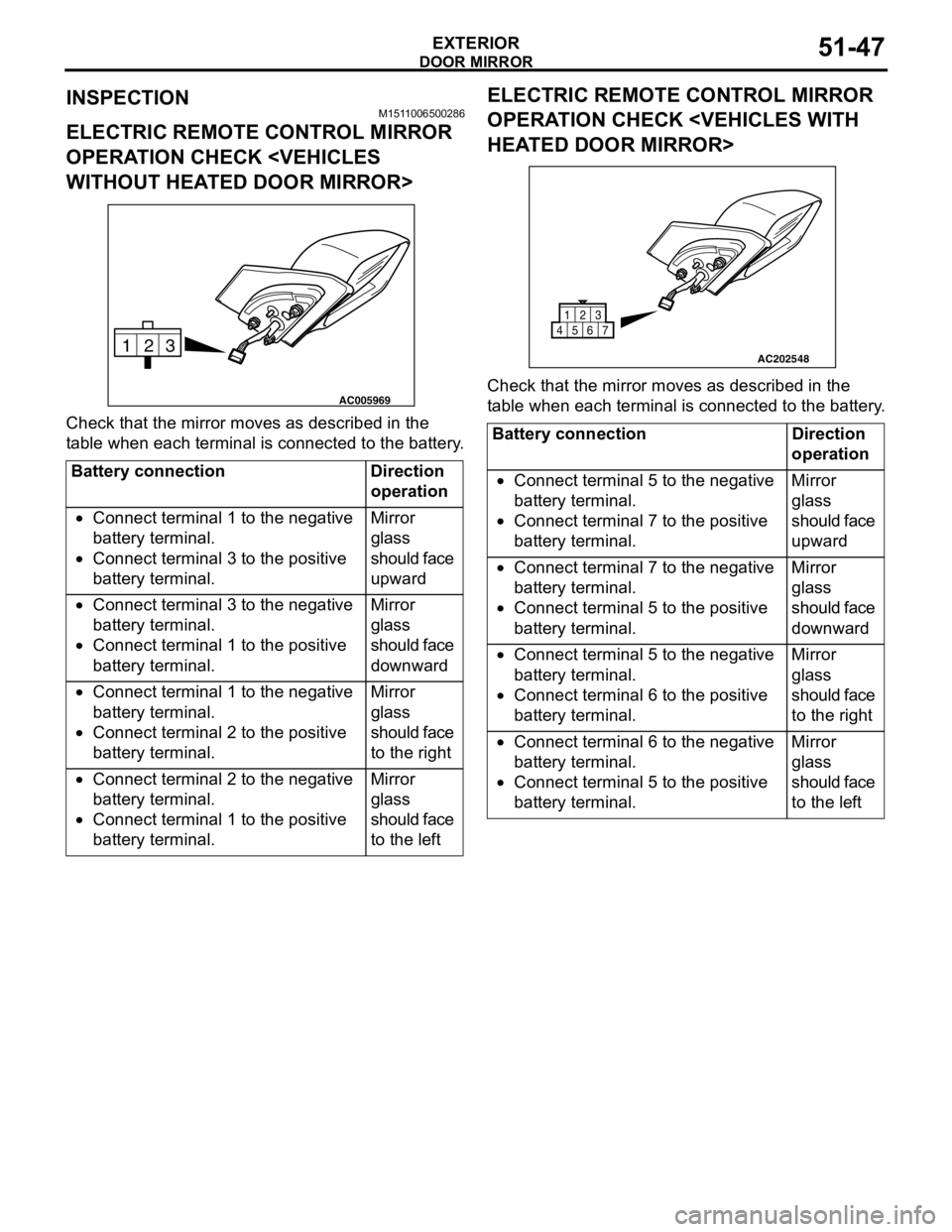
ELECTRIC REMOTE CONTROL MIRROR
OPERATION CHECK
Check that the mirror moves as described in the
table when each terminal is connected to the battery.
ELECTRIC REMOTE CONTROL MIRROR
OPERATION CHECK
Check that the mirror moves as described in the
table when each terminal is connected to the battery.
Battery connection Direction
operation
•Connect terminal 1 to the negative
battery terminal.
•Connect terminal 3 to the positive
battery terminal.Mirror
glass
should face
upward
•Connect terminal 3 to the negative
battery terminal.
•Connect terminal 1 to the positive
battery terminal.Mirror
glass
should face
downward
•Connect terminal 1 to the negative
battery terminal.
•Connect terminal 2 to the positive
battery terminal.Mirror
glass
should face
to the right
•Connect terminal 2 to the negative
battery terminal.
•Connect terminal 1 to the positive
battery terminal.Mirror
glass
should face
to the left
3 2
1
AC005969
Battery connection Direction
operation
•Connect terminal 5 to the negative
battery terminal.
•Connect terminal 7 to the positive
battery terminal.Mirror
glass
should face
upward
•Connect terminal 7 to the negative
battery terminal.
•Connect terminal 5 to the positive
battery terminal.Mirror
glass
should face
downward
•Connect terminal 5 to the negative
battery terminal.
•Connect terminal 6 to the positive
battery terminal.Mirror
glass
should face
to the right
•Connect terminal 6 to the negative
battery terminal.
•Connect terminal 5 to the positive
battery terminal.Mirror
glass
should face
to the left
AC202548
1
456723
Page 386 of 788
DOOR MIRROR
EXTERIOR51-48
DOOR MIRROR CONTROL SWITCH
CONTINUITY CHECKHEATED DOOR MIRROR CHECK
CAUTION
When relocating the car between locations with
extremely different temperatures (warm and
cold), leave the car in the location for a while to
adapt to the temperature prior to checking it.
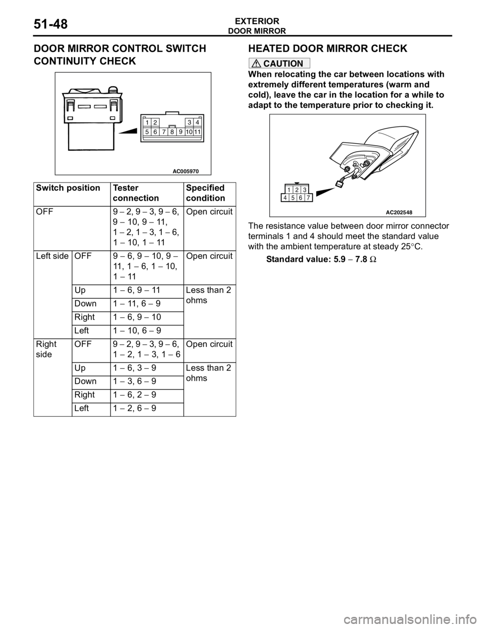
The resistance value between door mirror connector
terminals 1 and 4 should meet the standard value
with the ambient temperature at steady 25°C.
Standard value: 5.9 − 7.8 Ω Switch position Tester
connectionSpecified
condition
OFF 9 − 2, 9 − 3, 9 − 6,
9 − 10, 9 − 11 ,
1 − 2, 1 − 3, 1 − 6,
1 − 10, 1 − 11Open circuit
Left side OFF 9 − 6, 9 − 10, 9 −
11 , 1 − 6, 1 − 10,
1 − 11Open circuit
Up 1 − 6, 9 − 11 Less than 2
ohms
Down 1 − 11 , 6 − 9
Right 1 − 6, 9 − 10
Left 1 − 10, 6 − 9
Right
sideOFF 9 − 2, 9 − 3, 9 − 6,
1 − 2, 1 − 3, 1 − 6Open circuit
Up 1 − 6, 3 − 9 Less than 2
ohms
Down 1 − 3, 6 − 9
Right 1 − 6, 2 − 9
Left 1 − 2, 6 − 9
AC005970
2
14 3
5109
8
7 611
AC202548
1
456723