check MITSUBISHI LANCER 2005 Workshop Manual
[x] Cancel search | Manufacturer: MITSUBISHI, Model Year: 2005, Model line: LANCER, Model: MITSUBISHI LANCER 2005Pages: 788, PDF Size: 45.98 MB
Page 444 of 788
COMBINATION METER ASSEMBLY
CHASSIS ELECTRICAL54A-56
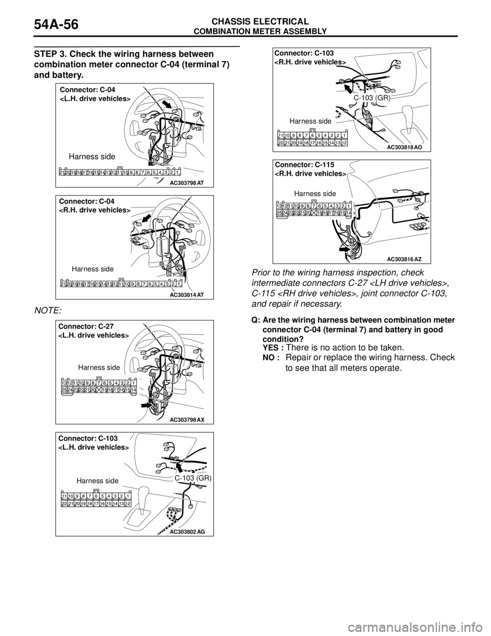
STEP 3. Check the wiring harness between
combination meter connector C-04 (terminal 7)
and battery.
NOTE: .Prior to the wiring harness inspection, check
intermediate connectors C-27
C-115
and repair if necessary.
Q: Are the wiring harness between combination meter
connector C-04 (terminal 7) and battery in good
condition?
YES :
There is no action to be taken.
NO : Repair or replace the wiring harness. Check
to see that all meters operate.
AC303798
Connector: C-04
Harness side
AT
AC303814
Connector: C-04
Harness side
AT
AC303798AX
Connector: C-27
Harness side
AC303802
Connector: C-103
Harness sideC-103 (GR)
AG
AC303818
AO
Connector: C-103
Harness side
C-103 (GR)
AC303816
Connector: C-115
Harness side
AZ
Page 445 of 788
COMBINATION METER ASSEMBLY
CHASSIS ELECTRICAL54A-57
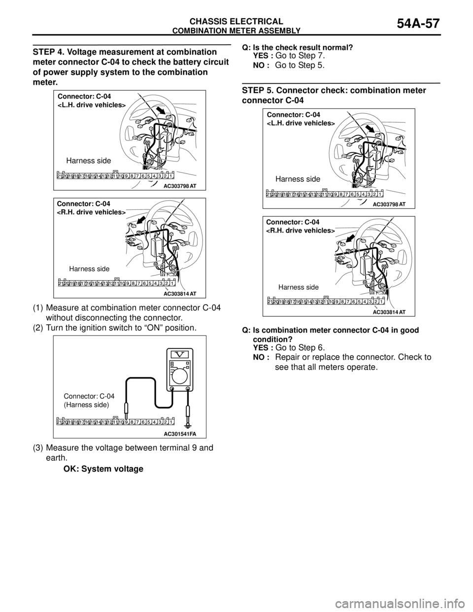
STEP 4. Voltage measurement at combination
meter connector C-04 to check the battery circuit
of power supply system to the combination
meter.
(1) Measure at combination meter connector C-04
without disconnecting the connector.
(2) Turn the ignition switch to “ON” position.
(3) Measure the voltage between terminal 9 and
earth.
OK: System voltageQ: Is the check result normal?
YES :
Go to Step 7.
NO : Go to Step 5.
STEP 5. Connector check: combination meter
connector C-04
Q: Is combination meter connector C-04 in good
condition?
YES :
Go to Step 6.
NO : Repair or replace the connector. Check to
see that all meters operate.
AC303798
Connector: C-04
Harness side
AT
AC303814
Connector: C-04
Harness side
AT
AC301541
Connector: C-04
(Harness side)
FA
AC303798
Connector: C-04
Harness side
AT
AC303814
Connector: C-04
Harness side
AT
Page 446 of 788
COMBINATION METER ASSEMBLY
CHASSIS ELECTRICAL54A-58
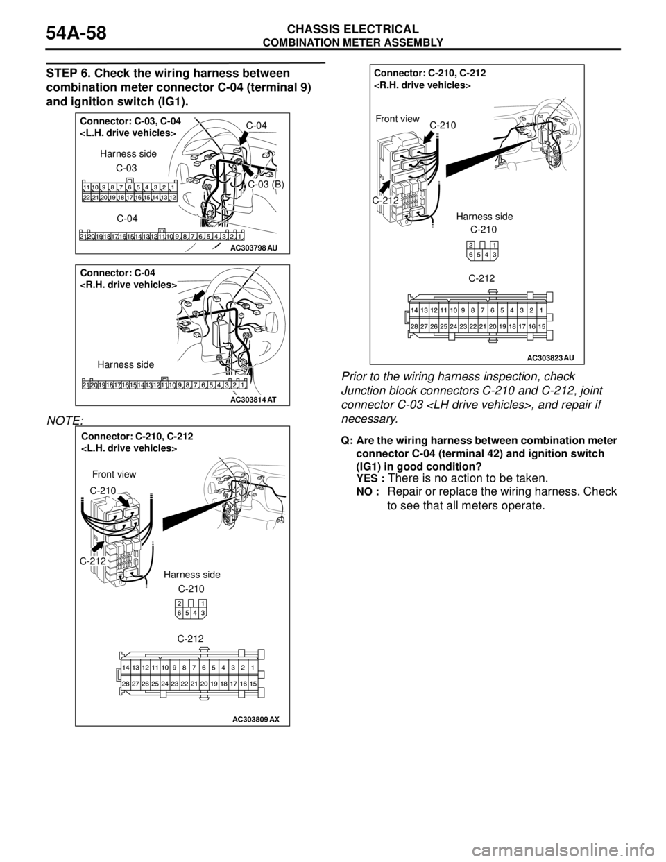
STEP 6. Check the wiring harness between
combination meter connector C-04 (terminal 9)
and ignition switch (IG1).
NOTE: Prior to the wiring harness inspection, check
Junction block connectors C-210 and C-212, joint
connector C-03
necessary.
Q: Are the wiring harness between combination meter
connector C-04 (terminal 42) and ignition switch
(IG1) in good condition?
YES :
There is no action to be taken.
NO : Repair or replace the wiring harness. Check
to see that all meters operate.
AC303798AU
Connector: C-03, C-04
C-03 (B)
C-04 C-03 Harness side
AC303814
Connector: C-04
Harness side
AT
AC303809
Connector: C-210, C-212
C-212
C-210
C-210 Harness side
C-212
AX
Front view
AC303823
Connector: C-210, C-212
C-210
C-212Front view
Harness side
C-210
C-212
AU
Page 447 of 788
COMBINATION METER ASSEMBLY
CHASSIS ELECTRICAL54A-59
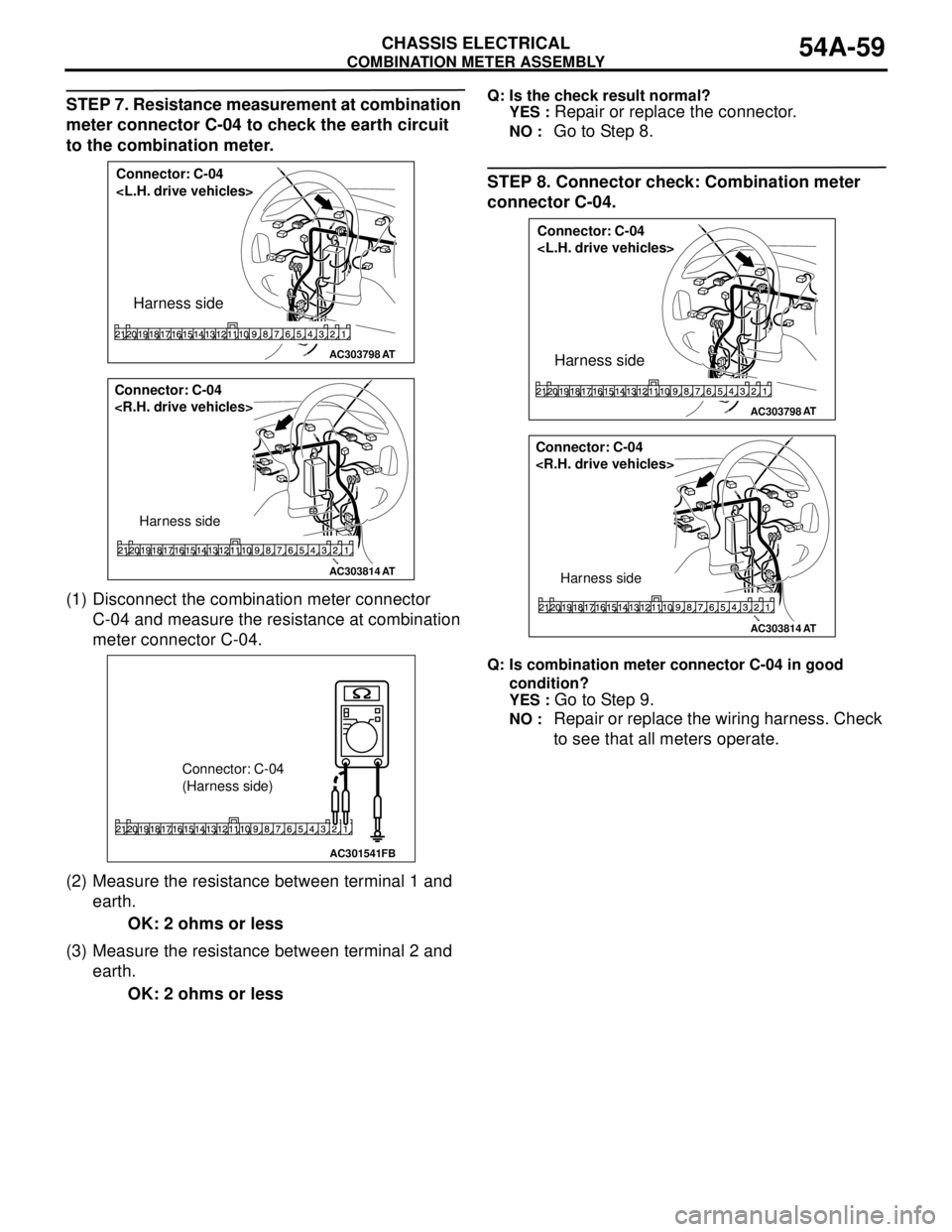
STEP 7. Resistance measurement at combination
meter connector C-04 to check the earth circuit
to the combination meter.
(1) Disconnect the combination meter connector
C-04 and measure the resistance at combination
meter connector C-04.
(2) Measure the resistance between terminal 1 and
earth.
OK: 2 ohms or less
(3) Measure the resistance between terminal 2 and
earth.
OK: 2 ohms or lessQ: Is the check result normal?
YES :
Repair or replace the connector.
NO : Go to Step 8.
STEP 8. Connector check: Combination meter
connector C-04.
Q: Is combination meter connector C-04 in good
condition?
YES :
Go to Step 9.
NO : Repair or replace the wiring harness. Check
to see that all meters operate.
AC303798
Connector: C-04
Harness side
AT
AC303814
Connector: C-04
Harness side
AT
AC301541FB
Connector: C-04
(Harness side)
AC303798
Connector: C-04
Harness side
AT
AC303814
Connector: C-04
Harness side
AT
Page 448 of 788
COMBINATION METER ASSEMBLY
CHASSIS ELECTRICAL54A-60
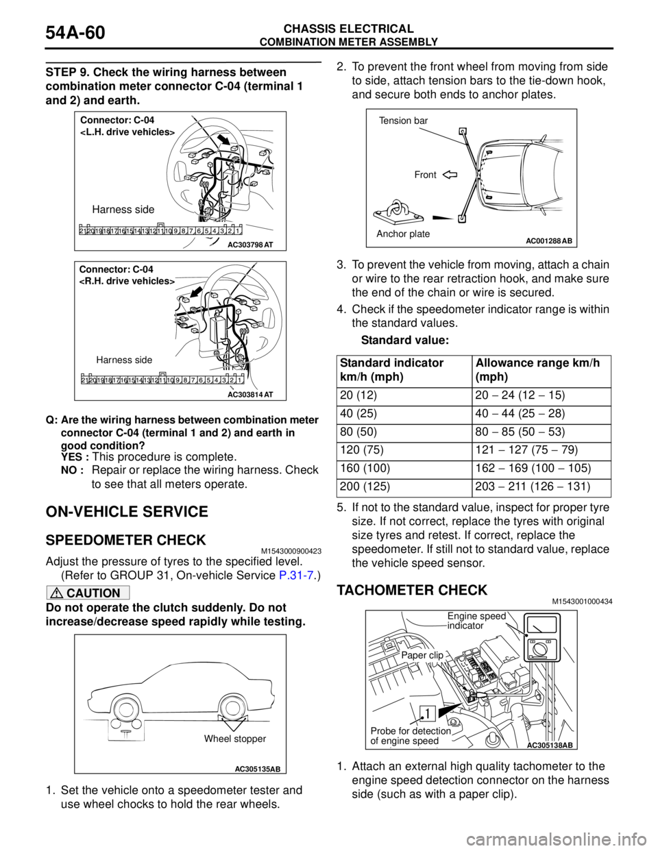
STEP 9. Check the wiring harness between
combination meter connector C-04 (terminal 1
and 2) and earth.
Q: Are the wiring harness between combination meter
connector C-04 (terminal 1 and 2) and earth in
good condition?
YES :
This procedure is complete.
NO : Repair or replace the wiring harness. Check
to see that all meters operate.
ON-VEHICLE SERVICE
SPEEDOMETER CHECKM1543000900423
Adjust the pressure of tyres to the specified level.
(Refer to GROUP 31, On-vehicle Service P.31-7.)
CAUTION
Do not operate the clutch suddenly. Do not
increase/decrease speed rapidly while testing.
1. Set the vehicle onto a speedometer tester and
use wheel chocks to hold the rear wheels.2. To prevent the front wheel from moving from side
to side, attach tension bars to the tie-down hook,
and secure both ends to anchor plates.
3. To prevent the vehicle from moving, attach a chain
or wire to the rear retraction hook, and make sure
the end of the chain or wire is secured.
4. Check if the speedometer indicator range is within
the standard values.
Standard value:
5. If not to the standard value, inspect for proper tyre
size. If not correct, replace the tyres with original
size tyres and retest. If correct, replace the
speedometer. If still not to standard value, replace
the vehicle speed sensor.
TACHOMETER CHECKM1543001000434
1. Attach an external high quality tachometer to the
engine speed detection connector on the harness
side (such as with a paper clip).
AC303798
Connector: C-04
Harness side
AT
AC303814
Connector: C-04
Harness side
AT
AC305135AB
Wheel stopper
Standard indicator
km/h (mph)Allowance range km/h
(mph)
20 (12) 20 − 24 (12 − 15)
40 (25) 40 − 44 (25 − 28)
80 (50) 80 − 85 (50 − 53)
120 (75) 121 − 127 (75 − 79)
160 (100) 162 − 169 (100 − 105)
200 (125) 203 − 211 (126 − 131)
AC001288
Tension bar
Front
Anchor plate
AB
AC305138AB
Engine speed
indicator
Paper clip
Probe for detection
of engine speed
Page 449 of 788
COMBINATION METER ASSEMBLY
CHASSIS ELECTRICAL54A-61
NOTE: For tachometer check, use an external
high quality inductive tachometer.
2. Compare the readings of the vehicle tachometer
and the external tachometer at every engine
speed, and check if the variations are within the
standard values.
Standard values:
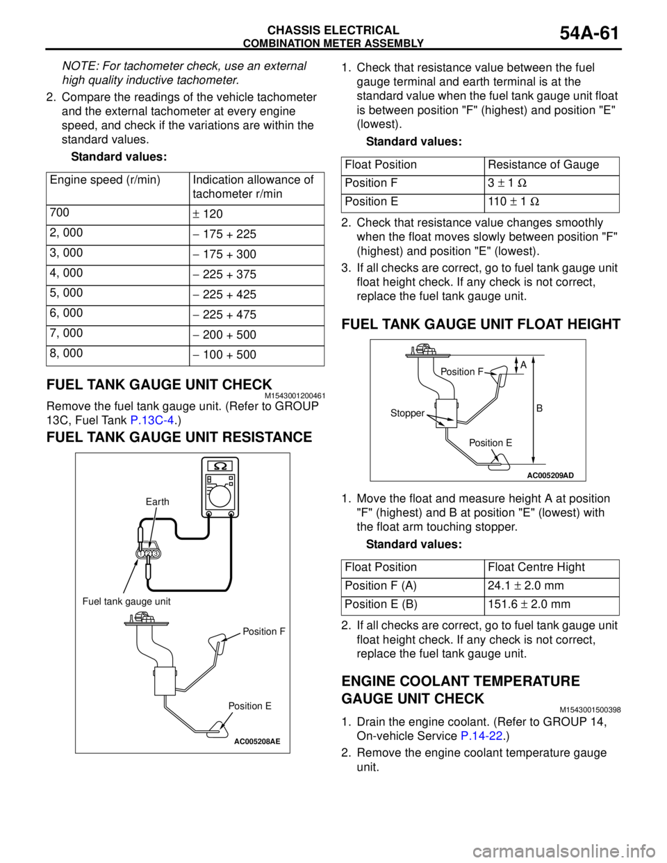
FUEL TANK GAUGE UNIT CHECKM1543001200461
Remove the fuel tank gauge unit. (Refer to GROUP
13C, Fuel Tank P.13C-4.)
FUEL TANK GAUGE UNIT RESISTANCE
1. Check that resistance value between the fuel
gauge terminal and earth terminal is at the
standard value when the fuel tank gauge unit float
is between position "F" (highest) and position "E"
(lowest).
Standard values:
2. Check that resistance value changes smoothly
when the float moves slowly between position "F"
(highest) and position "E" (lowest).
3. If all checks are correct, go to fuel tank gauge unit
float height check. If any check is not correct,
replace the fuel tank gauge unit.
FUEL TANK GAUGE UNIT FLOAT HEIGHT
1. Move the float and measure height A at position
"F" (highest) and B at position "E" (lowest) with
the float arm touching stopper.
Standard values:
2. If all checks are correct, go to fuel tank gauge unit
float height check. If any check is not correct,
replace the fuel tank gauge unit.
ENGINE COOLANT TEMPERATURE
GAUGE UNIT CHECK
M1543001500398
1. Drain the engine coolant. (Refer to GROUP 14,
On-vehicle Service P.14-22.)
2. Remove the engine coolant temperature gauge
unit. Engine speed (r/min) Indication allowance of
tachometer r/min
700
± 120
2, 000
− 175 + 225
3, 000
− 175 + 300
4, 000
− 225 + 375
5, 000
− 225 + 425
6, 000
− 225 + 475
7, 000
− 200 + 500
8, 000
− 100 + 500
AC005208
123
AE
Fuel tank gauge unit
Earth
Position F
Position E
Float Position Resistance of Gauge
Position F 3 ± 1 Ω
Position E 110 ± 1 Ω
Float Position Float Centre Hight
Position F (A) 24.1 ± 2.0 mm
Position E (B) 151.6 ± 2.0 mm
AC005209
AD
Position F
Position E
Stopper
A
B
Page 452 of 788
COMBINATION METER ASSEMBLY
CHASSIS ELECTRICAL54A-64
INSPECTIONM1543019502407
VEHICLE SPEED SENSOR CHECK
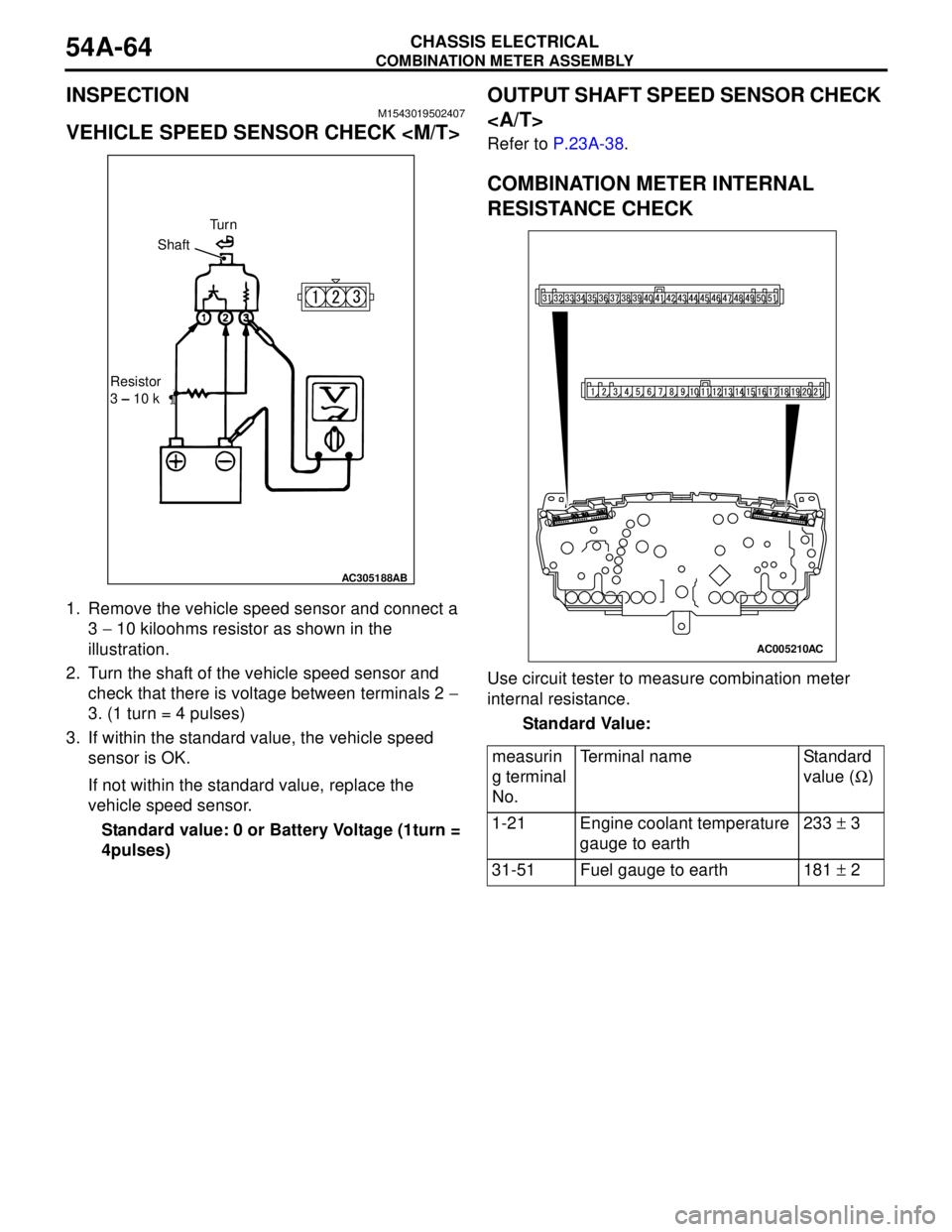
1. Remove the vehicle speed sensor and connect a
3 − 10 kiloohms resistor as shown in the
illustration.
2. Turn the shaft of the vehicle speed sensor and
check that there is voltage between terminals 2 −
3. (1 turn = 4 pulses)
3. If within the standard value, the vehicle speed
sensor is OK.
If not within the standard value, replace the
vehicle speed sensor.
Standard value: 0 or Battery Voltage (1turn =
4pulses)
OUTPUT SHAFT SPEED SENSOR CHECK
Refer to P.23A-38.
COMBINATION METER INTERNAL
RESISTANCE CHECK
Use circuit tester to measure combination meter
internal resistance.
Standard Value:
AC305188AB
Tu r n
Shaft
Resistor
3 – 10 k
measurin
g terminal
No.Terminal name Standard
value (Ω)
1-21 Engine coolant temperature
gauge to earth233 ± 3
31-51 Fuel gauge to earth 181 ± 2
AC005210AC
Page 455 of 788
HEADLAMP
CHASSIS ELECTRICAL54A-67
NOTE: Height from the floor to the centre of
the headlamps (Reference value): 840 mm
(3) Measure the distance from the centre line of
the vehicle to the centre of each headlamp.
Transfer the measurement to the screen.
Vertical tape or mark on the screen with
reference to the centre line of each headlamp
bulb.
HEADLAMP ADJUSTMENT
CAUTION
•Do not cover a headlamp for more than three
minutes to prevent the plastic headlamp lens
deformation.
•When adjusting one headlamp beam, make
sure that another headlamp is off by
disconnecting the connector from it. When
reconnecting the connector, make sure that
the headlamp beam is not disturbed
accidentally.
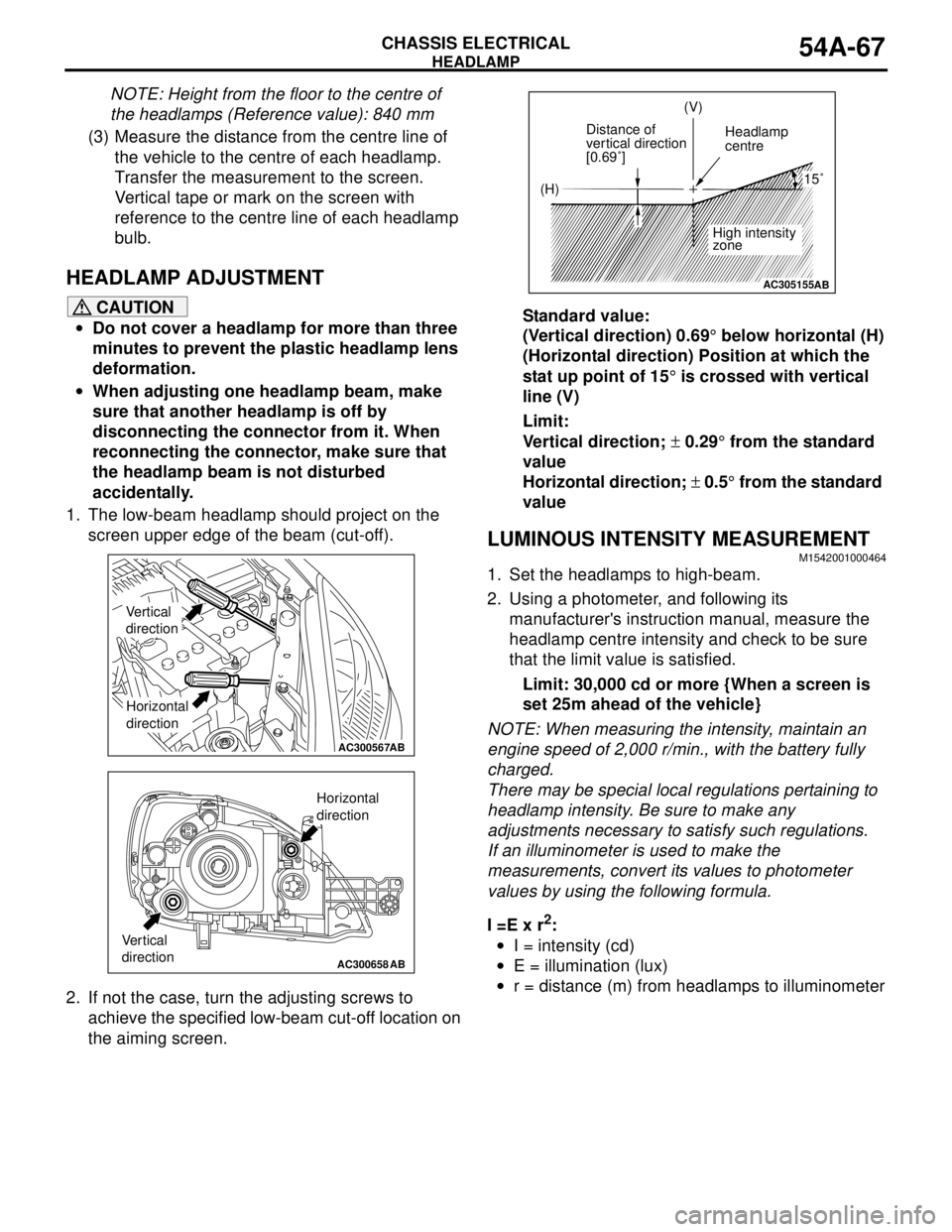
1. The low-beam headlamp should project on the
screen upper edge of the beam (cut-off).
2. If not the case, turn the adjusting screws to
achieve the specified low-beam cut-off location on
the aiming screen.Standard value:
(Vertical direction) 0.69° below horizontal (H)
(Horizontal direction) Position at which the
stat up point of 15° is crossed with vertical
line (V)
Limit:
Vertical direction; ± 0.29° from the standard
value
Horizontal direction; ± 0.5° from the standard
value
LUMINOUS INTENSITY MEASUREMENTM1542001000464
1. Set the headlamps to high-beam.
2. Using a photometer, and following its
manufacturer's instruction manual, measure the
headlamp centre intensity and check to be sure
that the limit value is satisfied.
Limit: 30,000 cd or more {When a screen is
set 25m ahead of the vehicle}
NOTE: When measuring the intensity, maintain an
engine speed of 2,000 r/min., with the battery fully
charged.
There may be special local regulations pertaining to
headlamp intensity. Be sure to make any
adjustments necessary to satisfy such regulations.
If an illuminometer is used to make the
measurements, convert its values to photometer
values by using the following formula.
I =E x r
2:
•I = intensity (cd)
•E = illumination (lux)
•r = distance (m) from headlamps to illuminometer
AC300567AB
Vertical
direction
Horizontal
direction
AC300658AB
Vertical
direction
Horizontal
direction
AC305155
(H)(V)
Distance of
vertical direction
[0.69˚]Headlamp
centre
High intensity
zone
15˚
AB
Page 458 of 788
HEADLAMP
CHASSIS ELECTRICAL54A-70
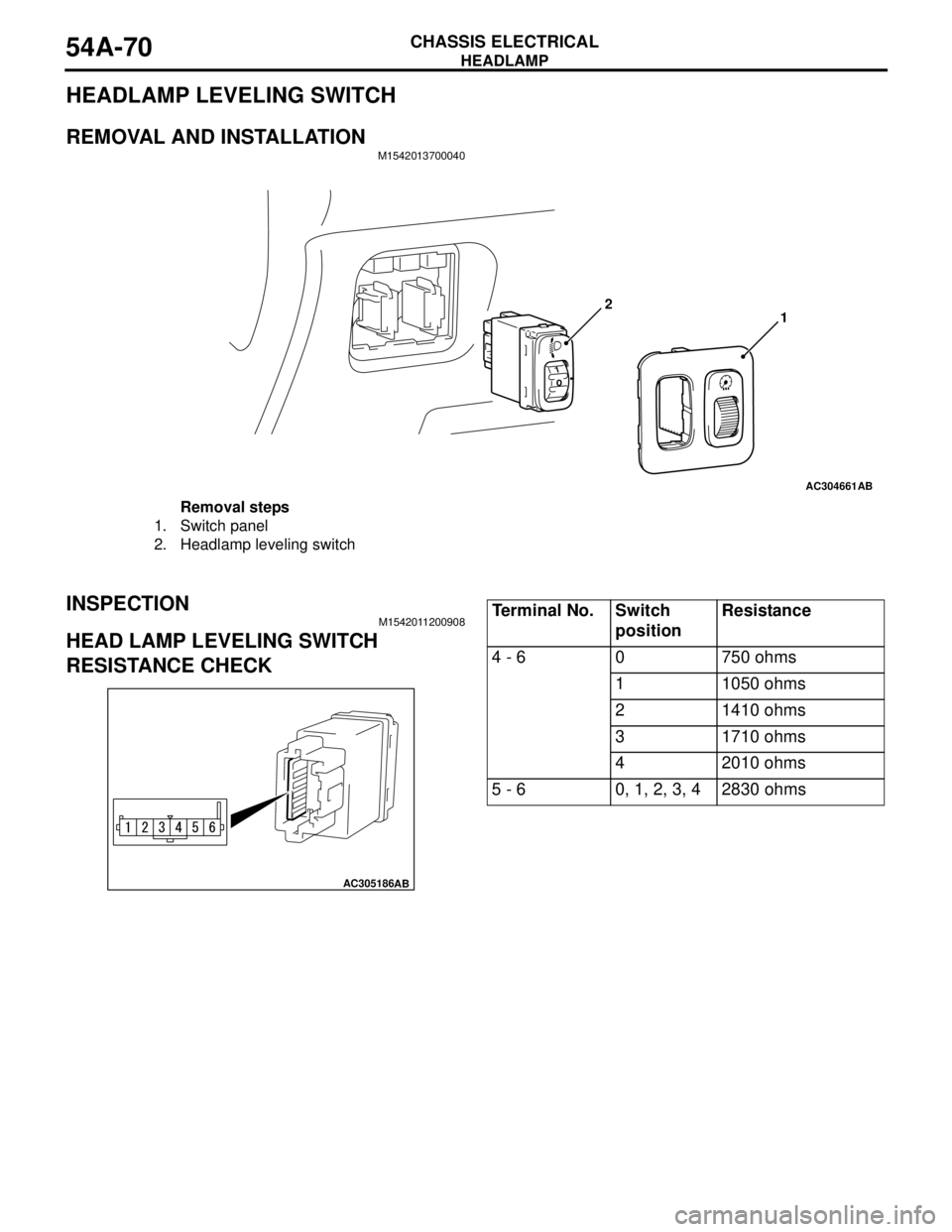
HEADLAMP LEVELING SWITCH
REMOVAL AND INSTALLATIONM1542013700040
INSPECTIONM1542011200908
HEAD LAMP LEVELING SWITCH
RESISTANCE CHECK
AC304661AB
2
1
Removal steps
1. Switch panel
2. Headlamp leveling switch
AC305186AB
Te r m i n a l N o . S w i t c h
positionResistance
4 - 6 0 750 ohms
1 1050 ohms
2 1410 ohms
3 1710 ohms
4 2010 ohms
5 - 6 0, 1, 2, 3, 4 2830 ohms
Page 459 of 788
FOG LAMP
CHASSIS ELECTRICAL54A-71
FOG LAMP
SERVICE SPECIFICATIONM1542000300343
SPECIAL TOOLM1542000600894
TROUBLESHOOTINGM1542000701292
When the front fog lamp switch is turned to ON with
the tail lamp or the headlamp on (the tail lamp switch
or the headlamp switch is ON), the fog lamp relay
turns on, and the fog lamps will illuminate.
If the tail lamps or the headlamps are turned off with
the lighting switch OFF while the fog lamps are on,
the front fog lamps turn off at the same time to
prevent unattended operation.
If the tail lamps are turned off by the headlamp
automatic shutdown function, the fog lamps turn off
at the same time. However, if the tail lamps illuminate
again, the fog lamps do not.
The front fog lamps are controlled by the Smart
Wiring System (SWS). For troubleshooting, refer to
respective Groups below.
•Not using SWS monitor: GROUP 54B, SWS
Troubleshooting P.54B-38.
•Using SWS monitor: GROUP 54C, SWS
Troubleshooting P.54C-22.
ON-VEHICLE SERVICE
FRONT FOG LAMP AIMING CHECKM1542001100438
After setting the vehicles to the following condition,
adjust the front fog lamp aiming.
•Check that the tyre inflation pressure is at the
value indicated on the tyre pressure labels.
•Set the vehicle to the unladen condition and park
it on a level surface.
•Have a single person (approximately 75 kg) sit in
the driver’s seat.•Run the engine at a speed of 2000 r/min to fully
charge the battery.
Turn on the front fog lamps and check that the
illumination is within the standard value range.
Standard value: Illuminates to within 40
metres
CAUTION
For the fog lamp which is not being measured,
disconnect that fog lamp’s connector if possible
so that it does not illuminate while carrying out
the adjustment. Furthermore, make sure that the
light axis does not get shifted when
re-connecting the connector.
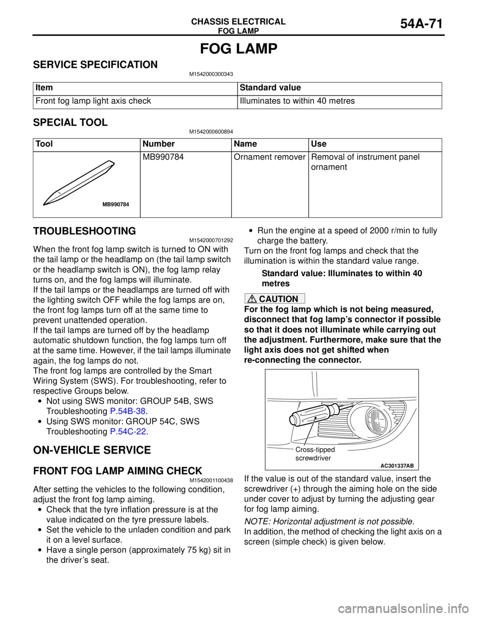
If the value is out of the standard value, insert the
screwdriver (+) through the aiming hole on the side
under cover to adjust by turning the adjusting gear
for fog lamp aiming.
NOTE: Horizontal adjustment is not possible.
In addition, the method of checking the light axis on a
screen (simple check) is given below. Item Standard value
Front fog lamp light axis check Illuminates to within 40 metres
Tool Number Name Use
MB990784 Ornament remover Removal of instrument panel
ornament
MB990784
AC301337
Cross-tipped
screwdriver
AB