check MITSUBISHI LANCER 2005 Workshop Manual
[x] Cancel search | Manufacturer: MITSUBISHI, Model Year: 2005, Model line: LANCER, Model: MITSUBISHI LANCER 2005Pages: 788, PDF Size: 45.98 MB
Page 323 of 788
TRUNK LID
BODY42-45
CAUTION
Install the trunk lid torsion bar
trunk lid torsion bar
reversed, the trunk lid torsion bar
be able to be installed because the special tool
will interfere with the trunk lid torsion bar
during installation of the trunk lid torsion bar
1. Identify the LH and RH torsion bars by the colour
mark made at the centre of each torsion bar.
2. Insert the left end of the trunk lid torsion bar
in the hole in the trunk lid hinge
3. Press portion A of the trunk lid torsion bar
right end against point A on the trunk lid hinge
4. Twist the portion B of the trunk lid torsion bar
moved from point B and pressed against point C
of the trunk lid hinge
Then force the portion into point D.
5. Twist the portion A of the trunk lid torsion bar
lid hinge
6. Attach the trunk lid torsion bar
lid hinge
trunk lid torsion bar
>>B<< TRUNK LID WEATHERSTRIP
INSTALLATION
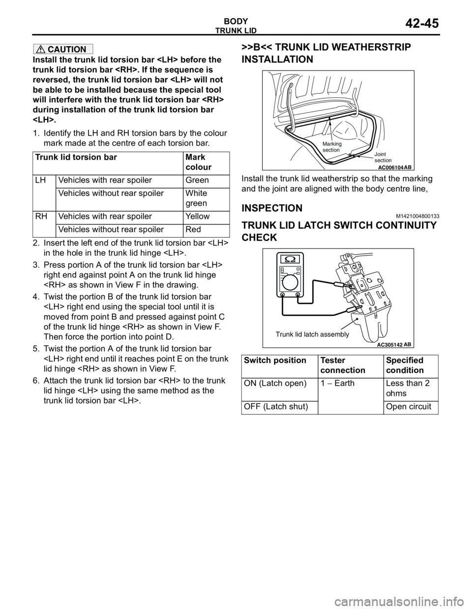
Install the trunk lid weatherstrip so that the marking
and the joint are aligned with the body centre line,
INSPECTIONM1421004800133
TRUNK LID LATCH SWITCH CONTINUITY
CHECK
Trunk lid torsion bar Mark
colour
LH Vehicles with rear spoiler Green
Vehicles without rear spoiler White
green
RH Vehicles with rear spoiler Yellow
Vehicles without rear spoiler Red
Switch position Tester
connectionSpecified
condition
ON (Latch open) 1 − Earth Less than 2
ohms
OFF (Latch shut) Open circuit
AC006104AB Joint
section
Marking
section
AC305142AB
Trunk lid latch assembly
Page 324 of 788
TA I L G AT E
BODY42-46
TA I L G AT E
SERVICE SPECIFICATIONSM1421000300288
SEALANTSM1424000500098
SPECIAL TOOLM1424000600170
TROUBLESHOOTINGM1424000700207
The tailgate system is controlled by the Smart Wiring
System (SWS). For troubleshooting, refer to GROUP
54B, Troubleshooting P.54B-17 or GROUP 54C,
Troubleshooting P.54C-4.
ON-VEHICLE SERVICE
TAILGATE FIT ADJUSTMENTM1424000900137
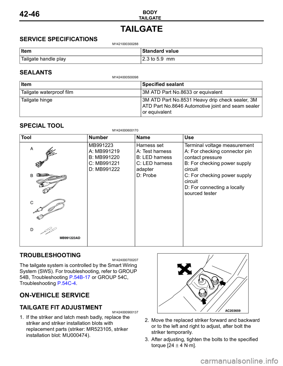
1. If the striker and latch mesh badly, replace the
striker and striker installation blots with
replacement parts (striker: MR523105, striker
installation blot: MU000474).2. Move the replaced striker forward and backward
or to the left and right to adjust, after bolt the
striker temporarily.
3. After adjusting, tighten the bolts to the specified
torque [24 ± 4 N⋅m]. Item Standard value
Tailgate handle play 2.3 to 5.9 mm
Item Specified sealant
Tailgate waterproof film 3M ATD Part No.8633 or equivalent
Tailgate hinge 3M ATD Part No.8531 Heavy drip check sealer, 3M
ATD Part No.8646 Automotive joint and seam sealer
or equivalent
Tool Number Name Use
MB991223
A: MB991219
B: MB991220
C: MB991221
D: MB991222Harness set
A: Test harness
B: LED harness
C: LED harness
adapter
D: ProbeTerminal voltage measurement
A: For checking connector pin
contact pressure
B: For checking power supply
circuit
C: For checking power supply
circuit
D: For connecting a locally
sourced tester
MB991223
A
D C
B
AD
AC203659
Page 325 of 788
TA I L G AT E
BODY42-47
NOTE:
When the bolt head interferes with the rear end
trim, rasp the interference area with a round file.4. If uneven clearance is present between tailgate
and body, reposition the hinge to adjust the
clearance.
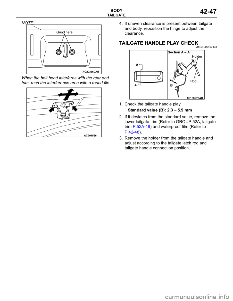
TAILGATE HANDLE PLAY CHECKM1424002400138
1. Check the tailgate handle play.
Standard value (B): 2.3 − 5.9 mm
2. If it deviates from the standard value, remove the
lower tailgate trim (Refer to GROUP 52A, tailgate
trim P.52A-19) and waterproof film (Refer to
P.42-48).
3. Remove the holder from the tailgate handle and
adjust according to the tailgate latch rod and
tailgate handle connection position.
AC203660AB
Grind here
AC201556
AC103270
A
ASection A – A
RodHolder
B
AC
Page 327 of 788
TA I L G AT E
BODY42-49
INSTALLATION SERVICE POINT
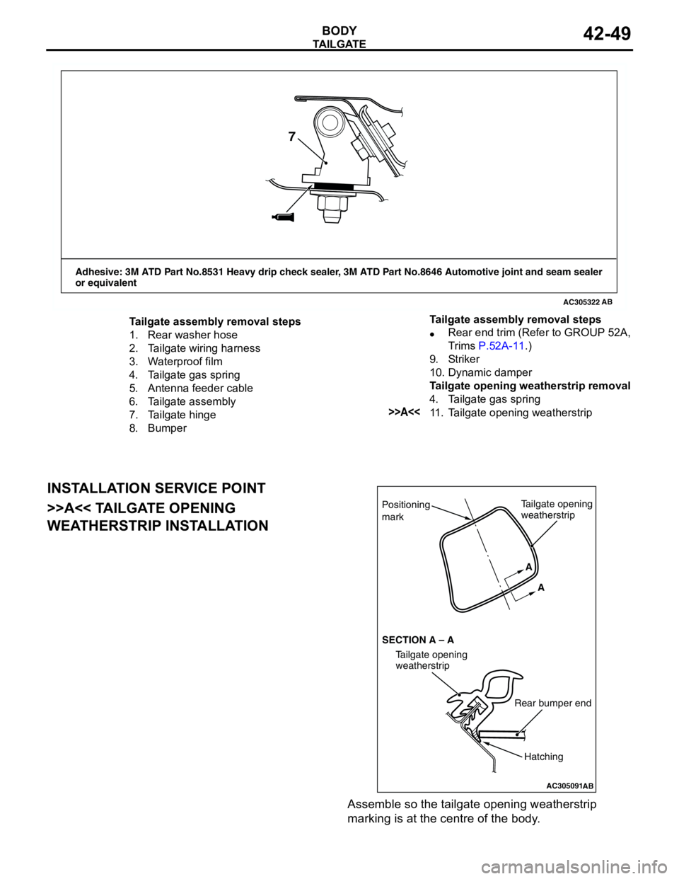
>>A<< TAILGATE OPENING
WEATHERSTRIP INSTALLATION
Assemble so the tailgate opening weatherstrip
marking is at the centre of the body.
AC305322
Adhesive: 3M ATD Part No.8531 Heavy drip check sealer, 3M ATD Part No.8646 Automotive joint and seam sealer
or equivalent
AB
7
Tailgate assembly removal steps
1. Rear washer hose
2. Tailgate wiring harness
3. Waterproof film
4. Tailgate gas spring
5. Antenna feeder cable
6. Tailgate assembly
7. Tailgate hinge
8. Bumper•Rear end trim (Refer to GROUP 52A,
Trims P.52A-11.)
9. Striker
10. Dynamic damper
Tailgate opening weatherstrip removal
4. Tailgate gas spring
>>A<<11. Tailgate opening weatherstrip Tailgate assembly removal steps
AC305091
Positioning
mark
AB
Tailgate opening
weatherstrip
Rear bumper end
Tailgate opening
weatherstrip SECTION A – AA
A
Hatching
Page 328 of 788
TA I L G AT E
BODY42-50
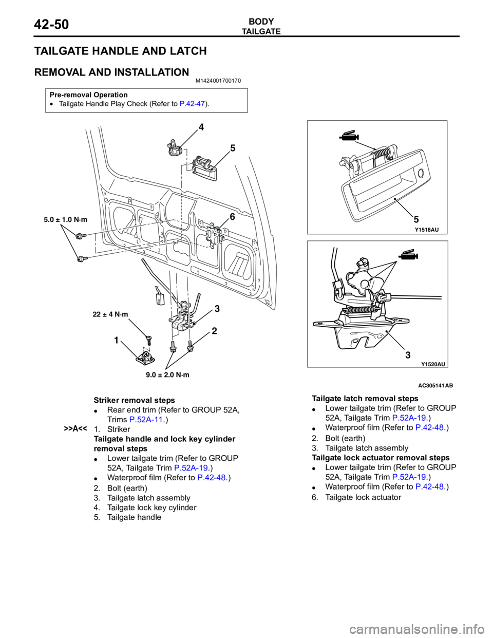
TAILGATE HANDLE AND LATCH
REMOVAL AND INSTALLATIONM1424001700170
Pre-removal Operation
•Tailgate Handle Play Check (Refer to P.42-47).
Y1518AU
Y1520AU
AC305141
4
5
6
3 35
5.0 ± 1.0 N·m
9.0 ± 2.0 N·m
AB
2
1
22 ± 4 N·m
Striker removal steps
•Rear end trim (Refer to GROUP 52A,
Trims P.52A-11.)
>>A<<1. Striker
Tailgate handle and lock key cylinder
removal steps
•Lower tailgate trim (Refer to GROUP
52A, Tailgate Trim P.52A-19.)
•Waterproof film (Refer to P.42-48.)
2. Bolt (earth)
3. Tailgate latch assembly
4. Tailgate lock key cylinder
5. Tailgate handleTailgate latch removal steps
•Lower tailgate trim (Refer to GROUP
52A, Tailgate Trim P.52A-19.)
•Waterproof film (Refer to P.42-48.)
2. Bolt (earth)
3. Tailgate latch assembly
Tailgate lock actuator removal steps
•Lower tailgate trim (Refer to GROUP
52A, Tailgate Trim P.52A-19.)
•Waterproof film (Refer to P.42-48.)
6. Tailgate lock actuator
Page 329 of 788
KEYLESS ENTRY SYSTEM
BODY42-51
INSTALLATION SERVICE POINT
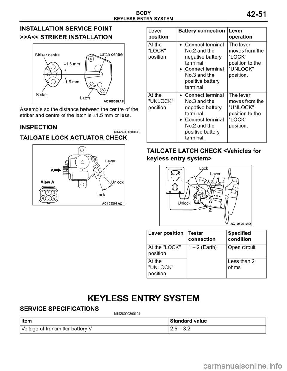
>>A<< STRIKER INSTALLATION
Assemble so the distance between the centre of the
striker and centre of the latch is ±1.5 mm or less.
INSPECTIONM1424001200142
TAILGATE LOCK ACTUATOR CHECK
TAILGATE LATCH CHECK
KEYLESS ENTRY SYSTEM
SERVICE SPECIFICATIONSM1428000300104
AC305098AB
Striker centre
StrikerLatch centre
Latch +1.5 mm
-1.5 mm
AC103292
A
View A
Unlock
Lock Lever
AC
Lever
positionBattery connection Lever
operation
At the
"LOCK"
position•Connect terminal
No.2 and the
negative battery
terminal.
•Connect terminal
No.3 and the
positive battery
terminal.The lever
moves from the
"LOCK"
position to the
"UNLOCK"
position.
At the
"UNLOCK"
position•Connect terminal
No.3 and the
negative battery
terminal.
•Connect terminal
No.2 and the
positive battery
terminal.The lever
moves from the
"UNLOCK"
position to the
"LOCK"
position.
Lever position Tester
connectionSpecified
condition
At the "LOCK"
position1 − 2 (Earth) Open circuit
At the
"UNLOCK"
positionLess than 2
ohms
AC103291
Lever
Unlock Lock
1
2
AD
Item Standard value
Voltage of transmitter battery V 2.5 − 3.2
Page 330 of 788
KEYLESS ENTRY SYSTEM
BODY42-52
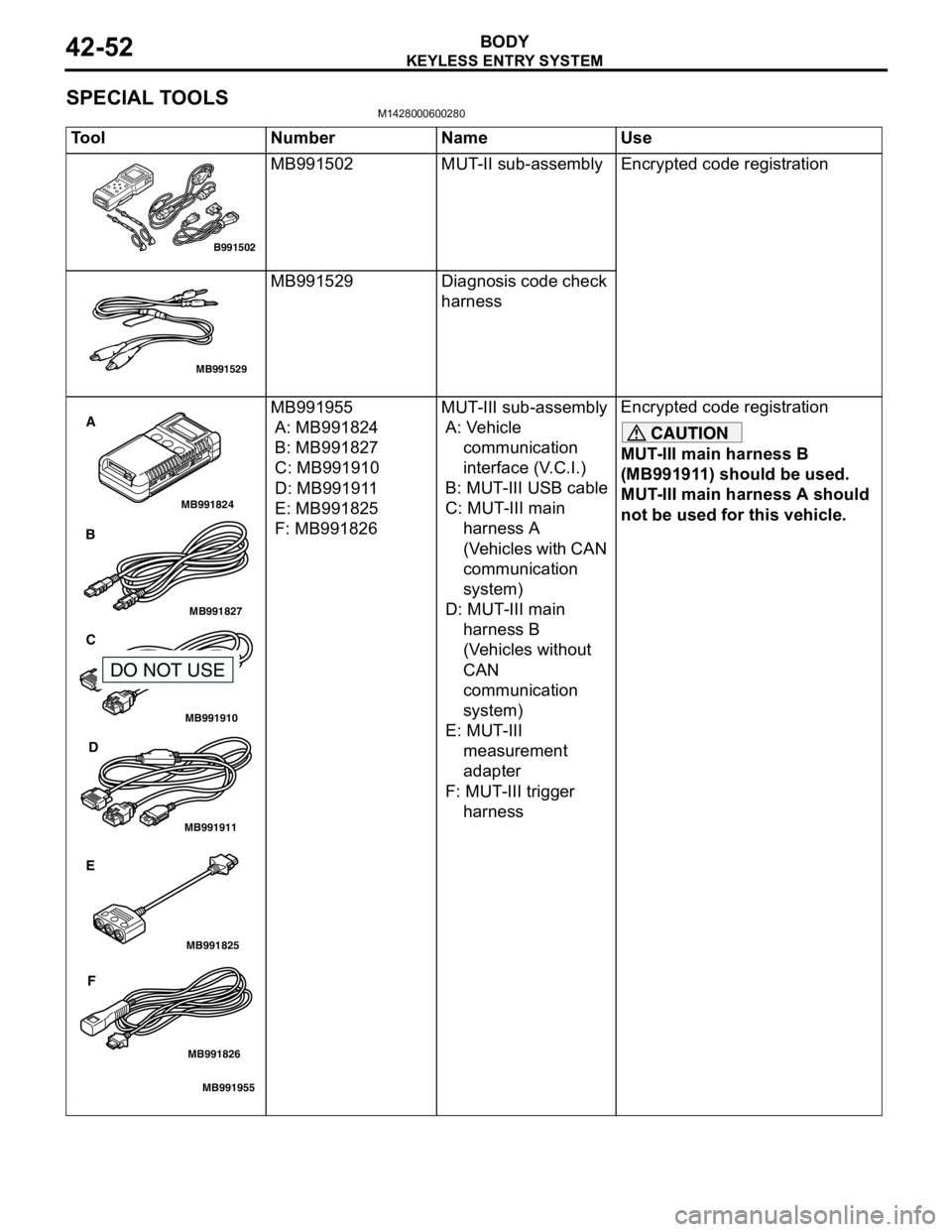
SPECIAL TOOLSM1428000600280
Tool Number Name Use
MB991502 MUT-II sub-assembly Encrypted code registration
MB991529 Diagnosis code check
harness
MB991955
A: MB991824
B: MB991827
C: MB991910
D: MB991911
E: MB991825
F: MB991826MUT-III sub-assembly
A: Vehicle
communication
interface (V.C.I.)
B: MUT-III USB cable
C: MUT-III main
harness A
(Vehicles with CAN
communication
system)
D: MUT-III main
harness B
(Vehicles without
CAN
communication
system)
E: MUT-III
measurement
adapter
F: MUT-III trigger
harnessEncrypted code registration
CAUTION
MUT-III main harness B
(MB991911) should be used.
MUT-III main harness A should
not be used for this vehicle.
B991502
MB991529
MB991910
MB991826
MB991955
MB991911
MB991824
MB991827
MB991825
A
B
C
D
E
F
DO NOT USE
Page 331 of 788
KEYLESS ENTRY SYSTEM
BODY42-53
TROUBLESHOOTINGM1428000700287
The keyless entry system is controlled by the Smart
Wiring System (SWS). For troubleshooting, refer to
GROUP 54B, Troubleshooting P.54B-17 or GROUP
54C, Troubleshooting P.54C-4.
ON-VEHICLE SERVICE
KEYLESS ENTRY SYSTEM CHECKM1428001400096
Check the system as described below. If the system
does not work, carry out troubleshooting. Refer to
GROUP 54B, Troubleshooting P.54B-17, refer to
GROUP 54C, Troubleshooting P.54C-4.
•Operate the transmitter to check that the doors
and tailgate can be locked and unlocked.
•Operate the transmitter to check that the
answerback function works in response to door
and tailgate
NOTE: The adjustment function allows you to
change the answerback setting as follows. Prior
to that check, confirm which setting is activated.
.
•The hazard warning lamps flash twice when
locked and once when unlocked. The room
lamp flashes twice when locked and
illuminates for 15 seconds when unlocked.
•The hazard warning lamps do not flash when
locked and flash once when unlocked. The
room lamp flashes twice when locked and
illuminates for 15 seconds when unlocked.
•The hazard warning lamps flash twice when
locked and do not flash when unlocked. The
room lamp flashes twice when locked and
illuminates for 15 seconds when unlocked.
•The hazard warning lamps do not flash when
both locked and unlocked. The room lamp
flashes twice when locked and illuminates for
15 seconds when unlocked.
KEYLESS ENTRY SYSTEM TIMER LOCK
FUNCTION INSPECTION
M1428004000138
Push the transmitter unlock button and check to see
that the doors and tailgate
seconds. If it doesn't, then execute troubleshooting
remedies. Refer to GROUP 54B, Troubleshooting
P.54B-17, refer to GROUP 54C, Troubleshooting
P.54C-4.
ENABLING/DISABLING THE
ANSWERBACK FUNCTION
M1428003200214
If the keyless entry system locks or unlocks the
doors, the room lamp flashes or illuminates, the
hazard warning lamp flashes (hazard answerback
function). The hazard answerback function can be
enabled or disabled according to the following
procedure:
ENABLING/DISABLING THE HAZARD
ANSWERBACK FUNCTION
The hazard answerback function can be enabled or
disabled by one of the two following procedures.
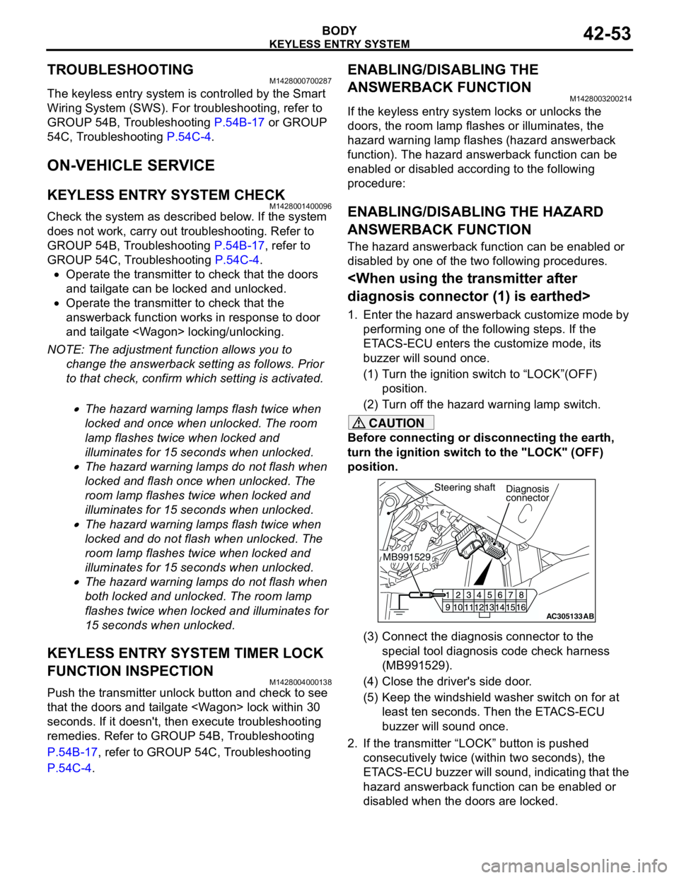
1. Enter the hazard answerback customize mode by
performing one of the following steps. If the
ETACS-ECU enters the customize mode, its
buzzer will sound once.
(1) Turn the ignition switch to “LOCK”(OFF)
position.
(2) Turn off the hazard warning lamp switch.
CAUTION
Before connecting or disconnecting the earth,
turn the ignition switch to the "LOCK" (OFF)
position.
(3) Connect the diagnosis connector to the
special tool diagnosis code check harness
(MB991529).
(4) Close the driver's side door.
(5) Keep the windshield washer switch on for at
least ten seconds. Then the ETACS-ECU
buzzer will sound once.
2. If the transmitter “LOCK” button is pushed
consecutively twice (within two seconds), the
ETACS-ECU buzzer will sound, indicating that the
hazard answerback function can be enabled or
disabled when the doors are locked.
AC305133AB
Diagnosis
connector
MB991529Steering shaft
Page 334 of 788
KEYLESS ENTRY SYSTEM
BODY42-56
WHEN THE SPECIAL TOOL DIAGNOSIS
CODE CHECK HARNESS (MB991529) IS
USED
1. Check that the doors lock normally when the key
is used.
2. Insert the ignition key.
CAUTION
Before connecting or disconnecting the earth,
turn the ignition switch to the "LOCK" (OFF)
position.
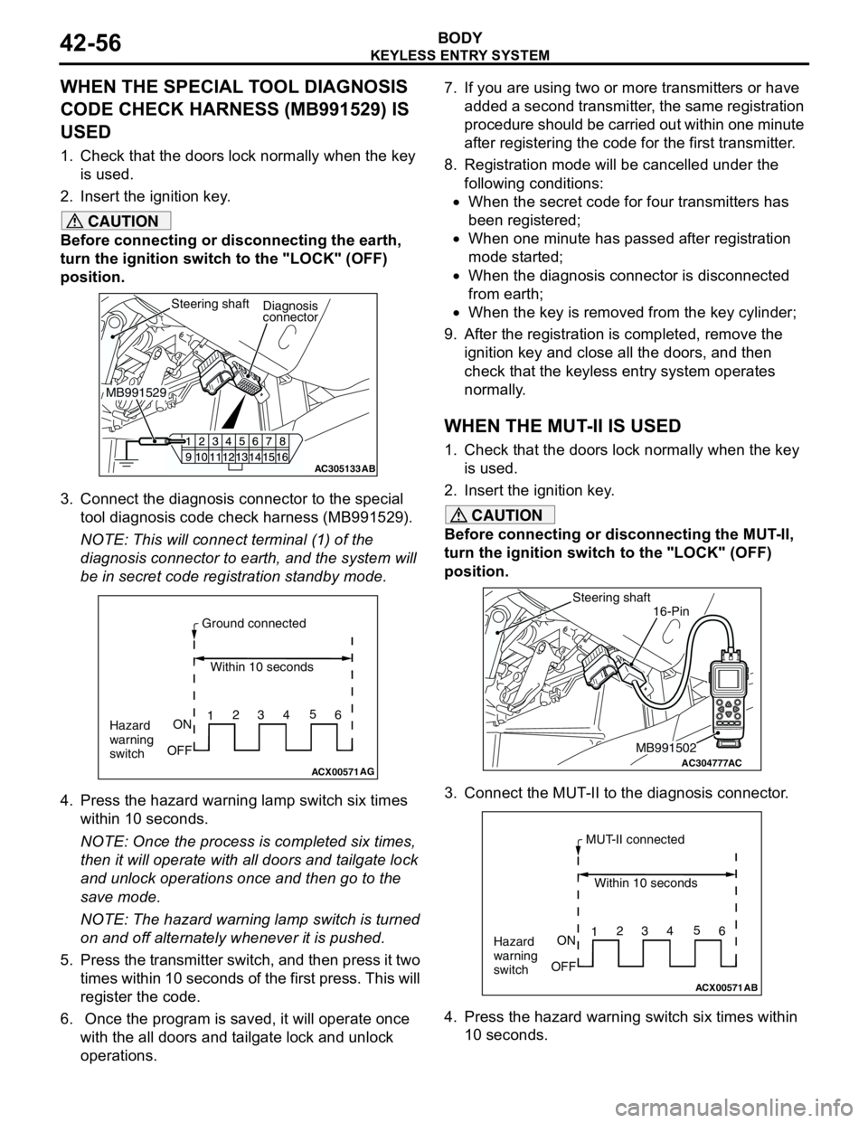
3. Connect the diagnosis connector to the special
tool diagnosis code check harness (MB991529).
NOTE: This will connect terminal (1) of the
diagnosis connector to earth, and the system will
be in secret code registration standby mode.
4. Press the hazard warning lamp switch six times
within 10 seconds.
NOTE: Once the process is completed six times,
then it will operate with all doors and tailgate lock
and unlock operations once and then go to the
save mode.
NOTE: The hazard warning lamp switch is turned
on and off alternately whenever it is pushed.
5. Press the transmitter switch, and then press it two
times within 10 seconds of the first press. This will
register the code.
6. Once the program is saved, it will operate once
with the all doors and tailgate lock and unlock
operations. 7. If you are using two or more transmitters or have
added a second transmitter, the same registration
procedure should be carried out within one minute
after registering the code for the first transmitter.
8. Registration mode will be cancelled under the
following conditions:
•When the secret code for four transmitters has
been registered;
•When one minute has passed after registration
mode started;
•When the diagnosis connector is disconnected
from earth;
•When the key is removed from the key cylinder;
9. After the registration is completed, remove the
ignition key and close all the doors, and then
check that the keyless entry system operates
normally.
WHEN THE MUT-II IS USED
1. Check that the doors lock normally when the key
is used.
2. Insert the ignition key.
CAUTION
Before connecting or disconnecting the MUT-II,
turn the ignition switch to the "LOCK" (OFF)
position.
3. Connect the MUT-II to the diagnosis connector.
4. Press the hazard warning switch six times within
10 seconds.
AC305133AB
Diagnosis
connector
MB991529Steering shaft
ACX00571
Ground connected
Within 10 seconds
Hazard
warning
switchON
OFF12345
6
AGAC304777
Steering shaft
ACMB991502
16-Pin
ACX00571
MUT-II connected
Within 10 seconds
Hazard
warning
switchON
OFF12345
6
AB
Page 335 of 788
KEYLESS ENTRY SYSTEM
BODY42-57
NOTE: Once the process is completed six times,
then it will operate with all doors and tailgate lock
and unlock operations once and then go to the
save mode.
NOTE: The hazard warning lamp switch is turned
on and off alternately whenever it is pushed.
5. Press the transmitter switch, and then press it two
times within 10 seconds of the first press. This will
register the code.
6. Once the program is saved, it will operate once
with the all doors and tailgate lock and unlock
operations.
7. If you are using two or more transmitters or have
added a second transmitter, the same registration
procedure should be carried out within one minute
after registering the code for the first transmitter.
8. Registration mode will be cancelled under the
following conditions:
•When the secret code for four transmitters has
been registered;
•When one minute has passed after registration
mode started;
•When the MUT-II is disconnected from the
diagnosis connector;
•When the key is removed from the key cylinder;
9. After the registration is completed, remove the
ignition key and close all the doors, and then
check that the keyless entry system operates
normally.
WHEN THE SPECIAL TOOL V. C. I.
(MB991824) IS USED
1. Check that the doors lock normally when the key
is used.
2. Insert the ignition key.
CAUTION
Before connecting or disconnecting the V. C. I.,
turn the ignition switch to the "LOCK" (OFF)
position.
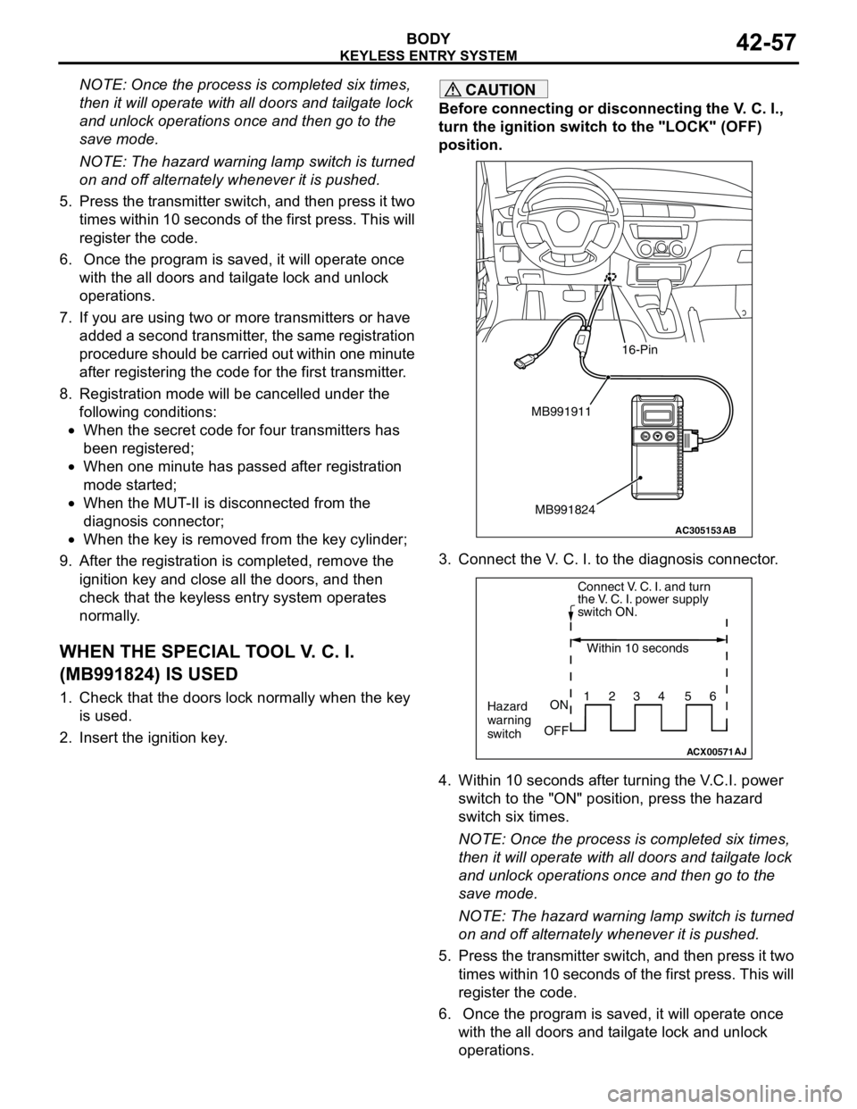
3. Connect the V. C. I. to the diagnosis connector.
4. Within 10 seconds after turning the V.C.I. power
switch to the "ON" position, press the hazard
switch six times.
NOTE: Once the process is completed six times,
then it will operate with all doors and tailgate lock
and unlock operations once and then go to the
save mode.
NOTE: The hazard warning lamp switch is turned
on and off alternately whenever it is pushed.
5. Press the transmitter switch, and then press it two
times within 10 seconds of the first press. This will
register the code.
6. Once the program is saved, it will operate once
with the all doors and tailgate lock and unlock
operations.
AC305153AB
MB991911
MB991824
16-Pin
ACX00571
Connect V. C. I. and turn
the V. C. I. power supply
switch ON.
Within 10 seconds
Hazard
warning
switchON
OFF1234 56
AJ