Air con MITSUBISHI LANCER 2005 User Guide
[x] Cancel search | Manufacturer: MITSUBISHI, Model Year: 2005, Model line: LANCER, Model: MITSUBISHI LANCER 2005Pages: 788, PDF Size: 45.98 MB
Page 31 of 788
TROUBLESHOOTING
ENGINE COOLING14-17
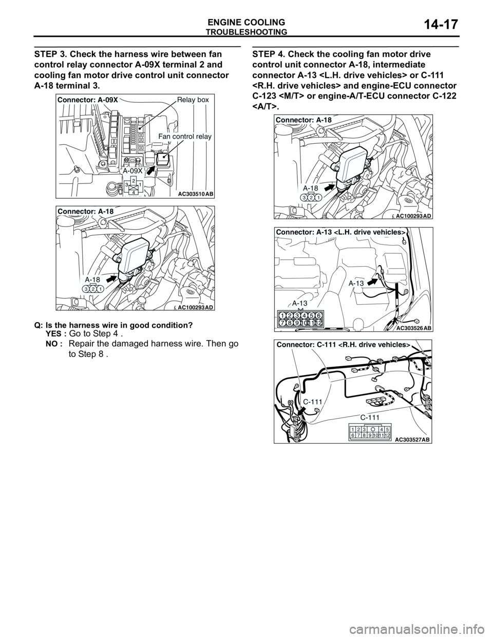
STEP 3. Check the harness wire between fan
control relay connector A-09X terminal 2 and
cooling fan motor drive control unit connector
A-18 terminal 3.
Q: Is the harness wire in good condition?
YES :
Go to Step 4 .
NO : Repair the damaged harness wire. Then go
to Step 8 .
STEP 4. Check the cooling fan motor drive
control unit connector A-18, intermediate
connector A-13
C-123
.
AC303510AB
Fan control relay
Relay boxConnector: A-09X
A-09X
AC100293
A-18
321
Connector: A-18
AD
AC100293
A-18
321
Connector: A-18
AD
AC303526
Connector: A-13
AB
A-13
A-13
AC303527
Connector: C-111
AB
C-111
C-111
615
121179
810234
Page 32 of 788
TROUBLESHOOTING
ENGINE COOLING14-18
Q: Are these connectors in good condition?
YES :
Go to Step 5 .
NO : Repair or replace the connector. Then go to
Step 8 .
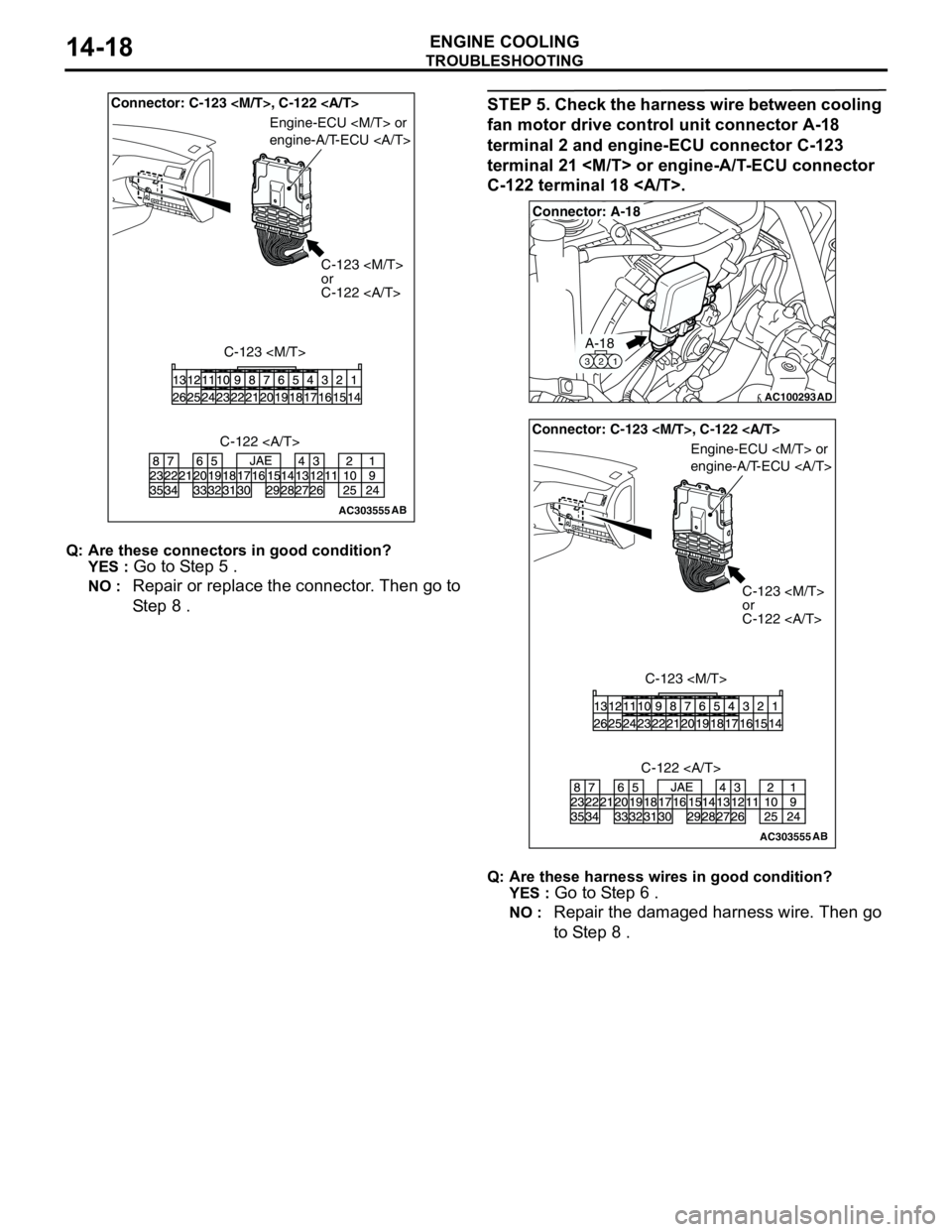
STEP 5. Check the harness wire between cooling
fan motor drive control unit connector A-18
terminal 2 and engine-ECU connector C-123
terminal 21
C-122 terminal 18 .
Q: Are these harness wires in good condition?
YES :
Go to Step 6 .
NO : Repair the damaged harness wire. Then go
to Step 8 .
AC303555AB
Connector: C-123
C-123
or
C-122
C-123
Engine-ECU
engine-A/T-ECU
C-122
AC100293
A-18
321
Connector: A-18
AD
AC303555AB
Connector: C-123
C-123
or
C-122
C-123
Engine-ECU
engine-A/T-ECU
C-122
Page 36 of 788
ON-VEHICLE SERVICE
ENGINE COOLING14-22
ON-VEHICLE SERVICE
ENGINE COOLANT LEAK CHECKM1141001000300
WARNING
When pressure testing the cooling system,
slowly release cooling system pressure to
avoid getting burned by hot coolant.
CAUTION
•Be sure to completely clean away any
moisture from the places checked.
•When the tester is taken out, be careful not to
spill any coolant.
•Be careful when installing and removing the
tester and when testing not to deform the
filler neck of the radiator.
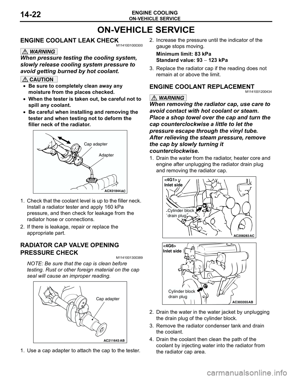
1. Check that the coolant level is up to the filler neck.
Install a radiator tester and apply 160 kPa
pressure, and then check for leakage from the
radiator hose or connections.
2. If there is leakage, repair or replace the
appropriate part.
RADIATOR CAP VALVE OPENING
PRESSURE CHECK
M1141001300389
NOTE: Be sure that the cap is clean before
testing. Rust or other foreign material on the cap
seal will cause an improper reading.
1. Use a cap adapter to attach the cap to the tester.2. Increase the pressure until the indicator of the
gauge stops moving.
Minimum limit: 83 kPa
Standard value: 93 − 123 kPa
3. Replace the radiator cap if the reading does not
remain at or above the limit.
ENGINE COOLANT REPLACEMENTM1141001200434
WARNING
When removing the radiator cap, use care to
avoid contact with hot coolant or steam.
Place a shop towel over the cap and turn the
cap counterclockwise a little to let the
pressure escape through the vinyl tube.
After relieving the steam pressure, remove
the cap by slowly turning it
counterclockwise.
1. Drain the water from the radiator, heater core and
engine after unplugging the radiator drain plug
and removing the radiator cap.
2. Drain the water in the water jacket by unplugging
the drain plug of the cylinder block.
3. Remove the radiator condenser tank and drain
the coolant.
4. Drain the coolant then clean the path of the
coolant by injecting water into the radiator from
the radiator cap area.
ACX01844
Cap adapter
Adapter
AC
AC211643AB
Cap adapter
AC208283AC
Cylinder block
drain plug
<4G1>
Inlet side
AC303355
<4G6>
Inlet side
Cylinder block
drain plug
AB
Page 37 of 788
ON-VEHICLE SERVICE
ENGINE COOLING14-23
5. Apply the designated sealant to the screw area of
the cylinder block drain plug, and then tighten to
the standard torque.
Specified sealant: 3M Nut Locking Part
No.4171 or equivalent
Tightening torque:
40 ± 5 N⋅m <4G1>
44 ± 5 N⋅m <4G6>
6. Securely tighten the drain plug of the radiator.
7. Reinstall the radiator condenser tank.
CAUTION
Do not use alcohol or methanol anti-freeze or any
engine coolants mixed with alcohol or methanol
anti-freeze. The use of an improper anti-freeze
can cause corrosion of the aluminium
components.
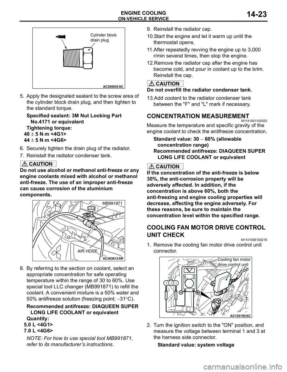
8. By referring to the section on coolant, select an
appropriate concentration for safe operating
temperature within the range of 30 to 60%. Use
special tool LLC changer (MB991871) to refill the
coolant. A convenient mixture is a 50% water and
50% antifreeze solution (freezing point: −31°C).
Recommended antifreeze: DIAQUEEN SUPER
LONG LIFE COOLANT or equivalent
Quantity:
5.0 L <4G1>
7.0 L <4G6>
NOTE: For how to use special tool MB991871,
refer to its manufacturer’s instructions.9. Reinstall the radiator cap.
10.Start the engine and let it warm up until the
thermostat opens.
11.After repeatedly revving the engine up to 3,000
r/min several times, then stop the engine.
12.Remove the radiator cap after the engine has
become cold, and pour in coolant up to the brim.
Reinstall the cap.
CAUTION
Do not overfill the radiator condenser tank.
13.Add coolant to the radiator condenser tank
between the "F" and "L" mark if necessary.
CONCENTRATION MEASUREMENTM1141001100352
Measure the temperature and specific gravity of the
engine coolant to check the antifreeze concentration.
Standard value: 30 − 60% (allowable
concentration range)
Recommended antifreeze: DIAQUEEN SUPER
LONG LIFE COOLANT or equivalent
CAUTION
If the concentration of the anti-freeze is below
30%, the anti-corrosion property will be
adversely affected. In addition, if the
concentration is above 60%, both the
anti-freezing and engine cooling properties will
decrease, affecting the engine adversely. For
these reasons, be sure to maintain the
concentration level within the specified range.
COOLING FAN MOTOR DRIVE CONTROL
UNIT CHECK
M1141006100216
1. Remove the cooling fan motor drive control unit
connector.
2. Turn the ignition switch to the "ON" position, and
measure the voltage between terminal 1 and 3 at
the harness side connector.
Standard value: system voltage
AC200625
Cylinder block
drain plug
AC
AC303612AB
MB991871
AIR HOSE
AC103195
Y1716AU
1 23
AC
Cooling fan motor
drive control unit
Page 45 of 788
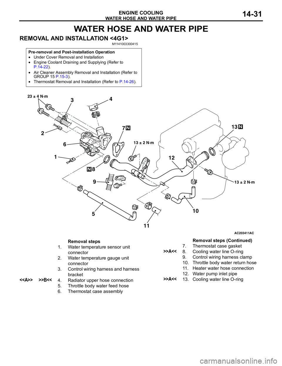
WATER HOSE AND WATER PIPE
ENGINE COOLING14-31
WATER HOSE AND WATER PIPE
REMOVAL AND INSTALLATION <4G1>M1141003300415
Pre-removal and Post-installation Operation
•Under Cover Removal and Installation
•Engine Coolant Draining and Supplying (Refer to
P.14-22).
•Air Cleaner Assembly Removal and Installation (Refer to
GROUP 15 P.15-3).
•Thermostat Removal and Installation (Refer to P.14-26).
AC203411
1 234
5 67
8
10 9
13 ± 2 N·m 23 ± 4 N·m
13 ± 2 N·m
N
N
AC
111213
N
Removal steps
1. Water temperature sensor unit
connector
2. Water temperature gauge unit
connector
3. Control wiring harness and harness
bracket
<> >>B<<4. Radiator upper hose connection
5. Throttle body water feed hose
6. Thermostat case assembly7. Thermostat case gasket
>>A<<8. Cooling water line O-ring
9. Control wiring harness clamp
10. Throttle body water return hose
11. Heater water hose connection
12. Water pump inlet pipe
>>A<<13. Cooling water line O-ringRemoval steps (Continued)
Page 47 of 788
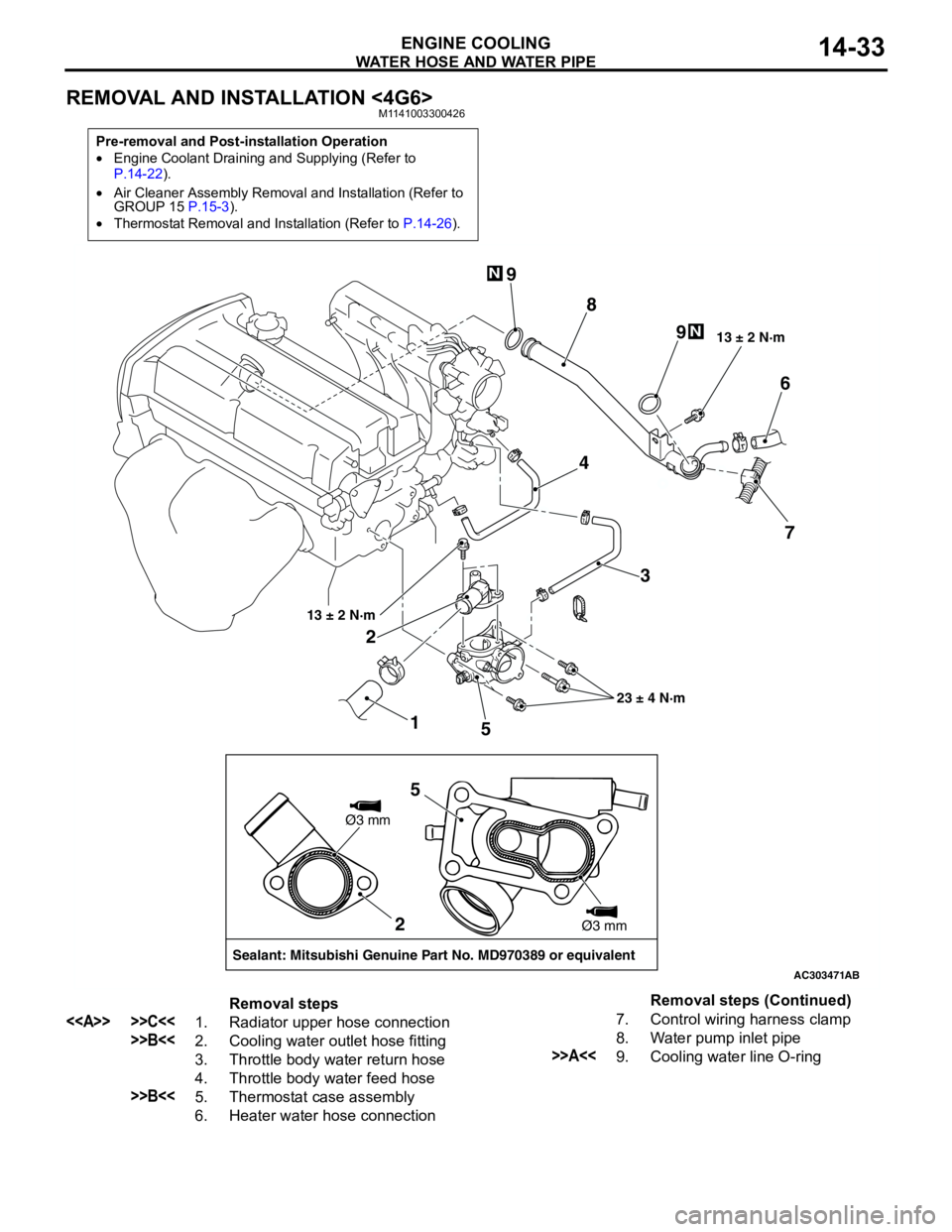
WATER HOSE AND WATER PIPE
ENGINE COOLING14-33
REMOVAL AND INSTALLATION <4G6>M1141003300426
Pre-removal and Post-installation Operation
•Engine Coolant Draining and Supplying (Refer to
P.14-22).
•Air Cleaner Assembly Removal and Installation (Refer to
GROUP 15 P.15-3).
•Thermostat Removal and Installation (Refer to P.14-26).
AC303471
1 23 4
56
7 8 9
9
13 ± 2 N·m
23 ± 4 N·m 13 ± 2 N·m
N
N
AB
2
Sealant: Mitsubishi Genuine Part No. MD970389 or equivalentØ3 mm
Ø3 mm
5
Removal steps
<> >>C<<1. Radiator upper hose connection
>>B<<2. Cooling water outlet hose fitting
3. Throttle body water return hose
4. Throttle body water feed hose
>>B<<5. Thermostat case assembly
6. Heater water hose connection7. Control wiring harness clamp
8. Water pump inlet pipe
>>A<<9. Cooling water line O-ringRemoval steps (Continued)
Page 53 of 788
15-1
GROUP 15
INTAKE AND
EXHAUST
CONTENTS
GENERAL INFORMATION . . . . . . . .15-2
SERVICE SPECIFICATION . . . . . . . .15-2
SPECIAL TOOL . . . . . . . . . . . . . . . . .15-2
AIR CLEANER . . . . . . . . . . . . . . . . . .15-3
REMOVAL AND INSTALLATION . . . . . . . . 15-3
INLET MANIFOLD . . . . . . . . . . . . . . .15-5
REMOVAL AND INSTALLATION <4G1> . . 15-5REMOVAL AND INSTALLATION <4G6> . . 15-6
INSPECTION . . . . . . . . . . . . . . . . . . . . . . . . 15-7
EXHAUST MANIFOLD . . . . . . . . . . . .15-7
REMOVAL AND INSTALLATION <4G1> . . 15-7
REMOVAL AND INSTALLATION <4G6> . . 15-9
INSPECTION . . . . . . . . . . . . . . . . . . . . . . . . 15-10
EXHAUST PIPE AND MAIN
MUFFLER . . . . . . . . . . . . . . . . . . . . . .15-11
REMOVAL AND INSTALLATION . . . . . . . . 15-11
Page 56 of 788
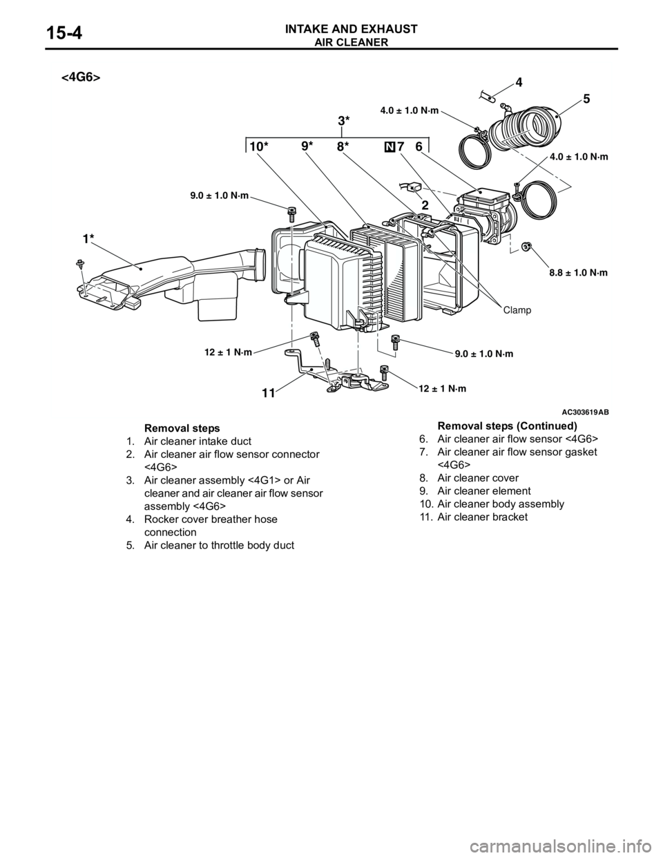
AIR CLEANER
INTAKE AND EXHAUST15-4
AC303619
4.0 ± 1.0 N·m 4.0 ± 1.0 N·m10*9*4
1*5
11
12 ± 1 N·m
9.0 ± 1.0 N·m 9.0 ± 1.0 N·m
AB
12 ± 1 N·m
Clamp
8*
3* <4G6>
6 7
N
2
8.8 ± 1.0 N·m
Removal steps
1. Air cleaner intake duct
2. Air cleaner air flow sensor connector
<4G6>
3. Air cleaner assembly <4G1> or Air
cleaner and air cleaner air flow sensor
assembly <4G6>
4. Rocker cover breather hose
connection
5. Air cleaner to throttle body duct6. Air cleaner air flow sensor <4G6>
7. Air cleaner air flow sensor gasket
<4G6>
8. Air cleaner cover
9. Air cleaner element
10. Air cleaner body assembly
11. Air cleaner bracketRemoval steps (Continued)
Page 68 of 788
CHARGING SYSTEM
ENGINE ELECTRICAL16-4
2. Turn the ignition switch to the "LOCK" (OFF)
position.
3. Disconnect the negative battery cable.
4. Connect a clamp-type DC test ammeter with a
range of 0 − 120 A to the alternator "B" terminal
output wire.
NOTE: The way of disconnecting the alternator
output wire and of connecting the ammeter is
possibly not found the problem that the output
current is dropping due to the insufficient
connection between terminal "B" and the output
wire.
5. Connect a digital-type voltmeter between the
alternator "B" terminal and the battery (+)
terminal. [Connect the (+) lead of the voltmeter to
the "B" terminal and the connect the (-) lead of the
voltmeter to the battery (+) cable].
6. Reconnect the negative battery cable.
7. Connect a tachometer or the MUT-II/III (Refer to
GROUP 11A − On-vehicle Service − Idle speed
check <4G1> P.11A-11 or GROUP 11C −
On-vehicle Service − Idle speed check <4G6>
P.11C-11).
8. Leave the hood open.
9. Start the engine.
10.With the engine running at 2,500 r/min, turn the
headlamps and other lamps on and off to adjust
the alternator load so that the value displayed on
the ammeter is slightly above 30 A.Adjust the engine speed by gradually decreasing
it until the value displayed on the ammeter is 30
A. Take a reading of the value displayed on the
voltmeter at this time.
Limit: maximum 0.3 V
NOTE: When the alternator output is high and the
value displayed on the ammeter does not
decrease until 30 A, set the value to 40 A. Read
the value displayed on the voltmeter at this time.
When the value range is 40 A, the limit is
maximum 0.4 V.
11.If the value displayed on the voltmeter is above
the limit value, there is probably a malfunction in
the alternator output wire, so check the wiring
between the alternator "B" terminal and the
battery (+) terminal (including fusible link).
If a terminal is not sufficiently tight or if the
harness has become discolored due to
overheating, repair and then test again.
12.After the test, run the engine at idle.
13.Turn off all lamps and the ignition switch.
14.Remove the tachometer or the MUT-II/III.
15.Disconnect the negative battery cable.
16.Disconnect the ammeter and voltmeter.
17.Connect the negative battery cable.
Page 77 of 788
CHARGING SYSTEM
ENGINE ELECTRICAL16-13
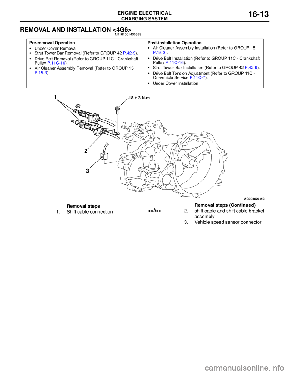
REMOVAL AND INSTALLATION <4G6>M1161001400559
Pre-removal Operation
•Under Cover Removal
•Strut Tower Bar Removal (Refer to GROUP 42 P.42-9).
•Drive Belt Removal (Refer to GROUP 11C - Crankshaft
Pulley P.11C-16).
•Air Cleaner Assembly Removal (Refer to GROUP 15
P.15-3).Post-installation Operation
•Air Cleaner Assembly Installation (Refer to GROUP 15
P.15-3).
•Drive Belt Installation (Refer to GROUP 11C - Crankshaft
Pulley P.11C-16).
•Strut Tower Bar Installation (Refer to GROUP 42 P.42-9).
•Drive Belt Tension Adjustment (Refer to GROUP 11C -
On-vehicle Service P.11C-7).
•Under Cover Installation
AC303826
1
2
318 ± 3 N·m
AB
Removal steps
1. Shift cable connection<>2. shift cable and shift cable bracket
assembly
3. Vehicle speed sensor connectorRemoval steps (Continued)