Air con MITSUBISHI LANCER 2005 Owner's Manual
[x] Cancel search | Manufacturer: MITSUBISHI, Model Year: 2005, Model line: LANCER, Model: MITSUBISHI LANCER 2005Pages: 788, PDF Size: 45.98 MB
Page 85 of 788

STARTING SYSTEM
ENGINE ELECTRICAL16-21
STARTER MOTOR ASSEMBLY
REMOVAL AND INSTALLATION <4G1>M1162001000628
REMOVAL SERVICE POINT
<> SHIFT CABLE AND SHIFT CABLE
BRACKET ASSEMBLY
Remove the shift cable bracket installation bolt with
the shift cable installed on the shift cable bracket,
and remove the shift cable and shift cable bracket
assembly from the transmission.
<> SHIFT CABLE CONNECTION
REMOVAL
Disengage the transmission, and remove the shift
cable assembly from the transmission.
<
Remove the starter assembly from above the
vehicle.
Pre-removal and Post-installation Operation
•Air Cleaner Assembly Removal and Installation (Refer to
GROUP 15 P.15-3).
•Battery and Battery Tray Removal and Installation
AC303962AB
1
1 2
3
56
7
4
30 ± 3 N·m18 ± 3 N·m
12 ± 2 N·m
Removal steps
1. Shift cable connection
<>2. shift cable and shift cable bracket
assembly
<>3. Shift cable connection 4. Starter connector and terminal
5. Harness bracket
6. Harness bracket <
Page 86 of 788
STARTING SYSTEM
ENGINE ELECTRICAL16-22
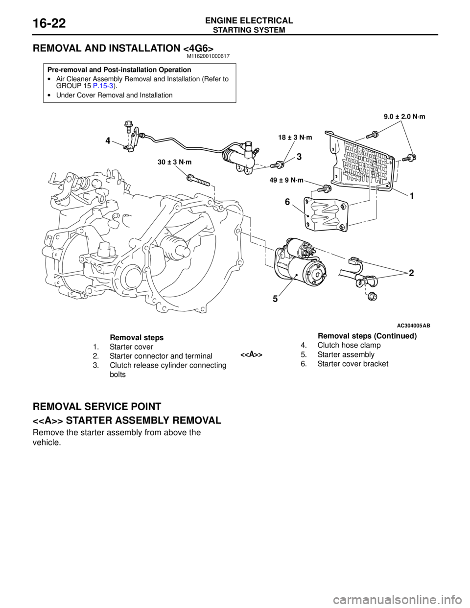
REMOVAL AND INSTALLATION <4G6>M1162001000617
REMOVAL SERVICE POINT
<> STARTER ASSEMBLY REMOVAL
Remove the starter assembly from above the
vehicle.
Pre-removal and Post-installation Operation
•Air Cleaner Assembly Removal and Installation (Refer to
GROUP 15 P.15-3).
•Under Cover Removal and Installation
AC304005
521
6
49 ± 9 N·m 18 ± 3 N·m9.0 ± 2.0 N·m
30 ± 3 N·m
AB
4
3
Removal steps
1. Starter cover
2. Starter connector and terminal
3. Clutch release cylinder connecting
bolts4. Clutch hose clamp
<>5. Starter assembly
6. Starter cover bracketRemoval steps (Continued)
Page 91 of 788
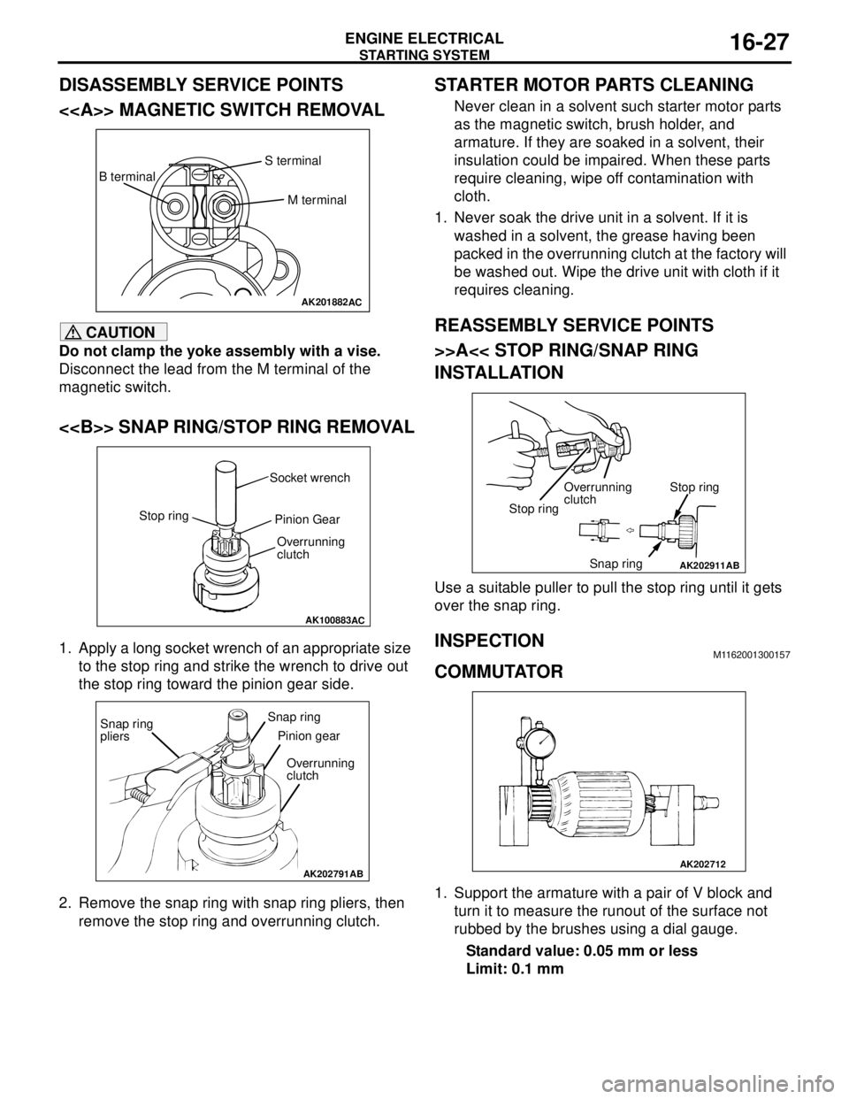
Page 94 of 788
IGNITION SYSTEM
ENGINE ELECTRICAL16-30
IGNITION SYSTEM
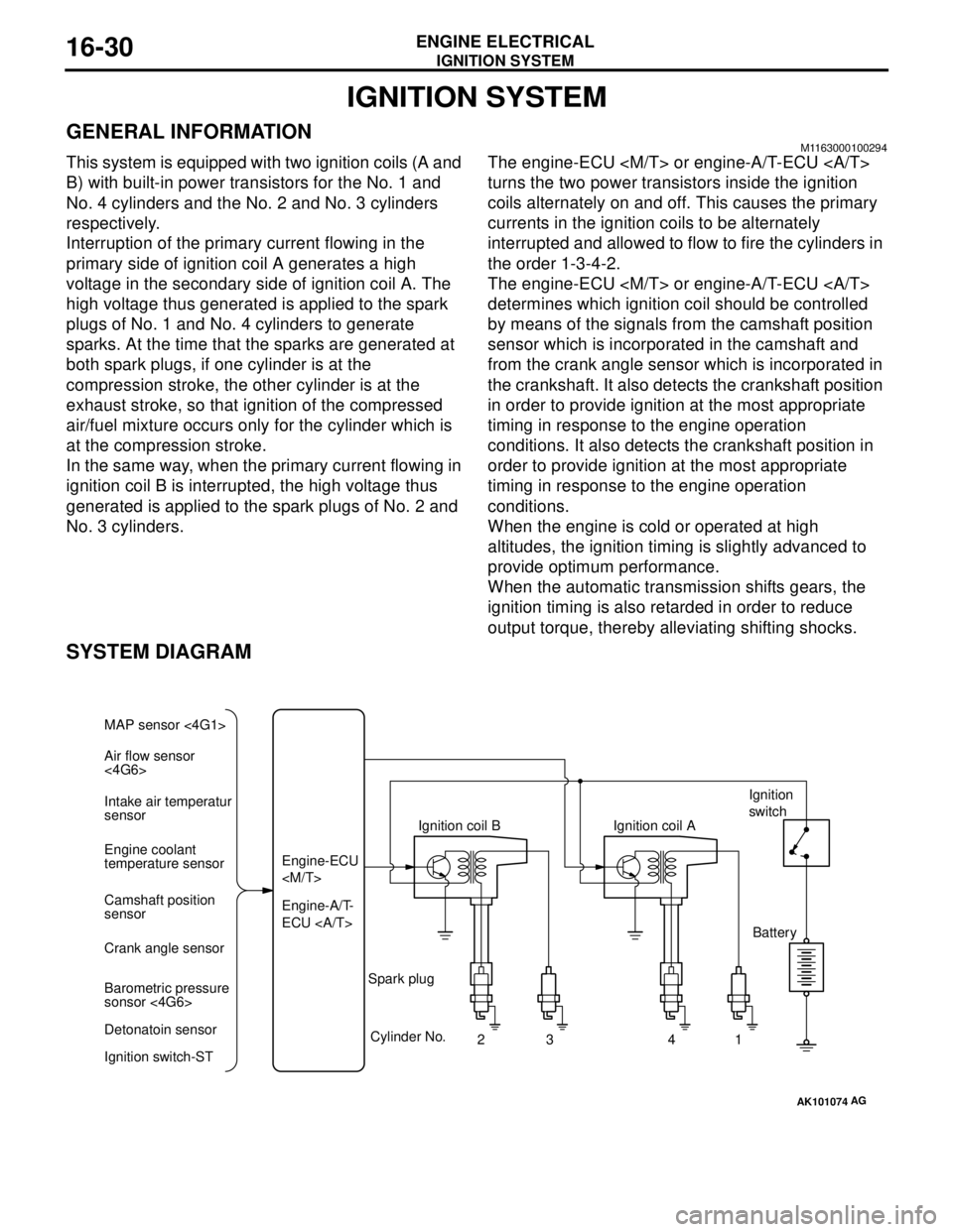
GENERAL INFORMATIONM1163000100294
This system is equipped with two ignition coils (A and
B) with built-in power transistors for the No. 1 and
No. 4 cylinders and the No. 2 and No. 3 cylinders
respectively.
Interruption of the primary current flowing in the
primary side of ignition coil A generates a high
voltage in the secondary side of ignition coil A. The
high voltage thus generated is applied to the spark
plugs of No. 1 and No. 4 cylinders to generate
sparks. At the time that the sparks are generated at
both spark plugs, if one cylinder is at the
compression stroke, the other cylinder is at the
exhaust stroke, so that ignition of the compressed
air/fuel mixture occurs only for the cylinder which is
at the compression stroke.
In the same way, when the primary current flowing in
ignition coil B is interrupted, the high voltage thus
generated is applied to the spark plugs of No. 2 and
No. 3 cylinders.The engine-ECU
turns the two power transistors inside the ignition
coils alternately on and off. This causes the primary
currents in the ignition coils to be alternately
interrupted and allowed to flow to fire the cylinders in
the order 1-3-4-2.
The engine-ECU
determines which ignition coil should be controlled
by means of the signals from the camshaft position
sensor which is incorporated in the camshaft and
from the crank angle sensor which is incorporated in
the crankshaft. It also detects the crankshaft position
in order to provide ignition at the most appropriate
timing in response to the engine operation
conditions. It also detects the crankshaft position in
order to provide ignition at the most appropriate
timing in response to the engine operation
conditions.
When the engine is cold or operated at high
altitudes, the ignition timing is slightly advanced to
provide optimum performance.
When the automatic transmission shifts gears, the
ignition timing is also retarded in order to reduce
output torque, thereby alleviating shifting shocks.
SYSTEM DIAGRAM
AK101074
Air flow sensor
<4G6> MAP sensor <4G1>
Intake air temperatur
sensor
Engine coolant
temperature sensor
Camshaft position
sensor
Crank angle sensor
Barometric pressure
sonsor <4G6>
Detonatoin sensor
Ignition switch-STEngine-A/T-
ECU Engine-ECU
Cylinder No.
23 4
AG
1 Spark plugIgnition coil AIgnition
switch
Battery
Page 96 of 788
IGNITION SYSTEM
ENGINE ELECTRICAL16-32
ON-VEHICLE SERVICE
IGNITION COIL (WITH BUILT-IN POWER
TRANSISTOR) CHECK
M1163001200324
Check by the following procedure, and replace if
there is a malfunction.
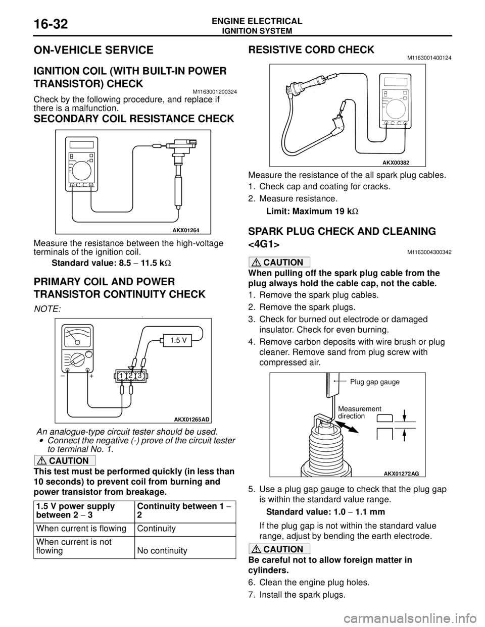
SECONDARY COIL RESISTANCE CHECK
Measure the resistance between the high-voltage
terminals of the ignition coil.
Standard value: 8.5 − 11.5 kΩ
PRIMARY COIL AND POWER
TRANSISTOR CONTINUITY CHECK
NOTE: .•
An analogue-type circuit tester should be used.
•Connect the negative (-) prove of the circuit tester
to terminal No. 1.
CAUTION
This test must be performed quickly (in less than
10 seconds) to prevent coil from burning and
power transistor from breakage.
RESISTIVE CORD CHECKM1163001400124
Measure the resistance of the all spark plug cables.
1. Check cap and coating for cracks.
2. Measure resistance.
Limit: Maximum 19 kΩ
SPARK PLUG CHECK AND CLEANING
<4G1>
M1163004300342
CAUTION
When pulling off the spark plug cable from the
plug always hold the cable cap, not the cable.
1. Remove the spark plug cables.
2. Remove the spark plugs.
3. Check for burned out electrode or damaged
insulator. Check for even burning.
4. Remove carbon deposits with wire brush or plug
cleaner. Remove sand from plug screw with
compressed air.
5. Use a plug gap gauge to check that the plug gap
is within the standard value range.
Standard value: 1.0 − 1.1 mm
If the plug gap is not within the standard value
range, adjust by bending the earth electrode.
CAUTION
Be careful not to allow foreign matter in
cylinders.
6. Clean the engine plug holes.
7. Install the spark plugs. 1.5 V power supply
between 2 − 3Continuity between 1 −
2
When current is flowing Continuity
When current is not
flowing No continuity
AKX01264
AKX01265AD
1.5 V
123 +
–
AKX00382
AKX01272
AG
Plug gap gauge
Measurement
direction
Page 99 of 788
IGNITION SYSTEM
ENGINE ELECTRICAL16-35
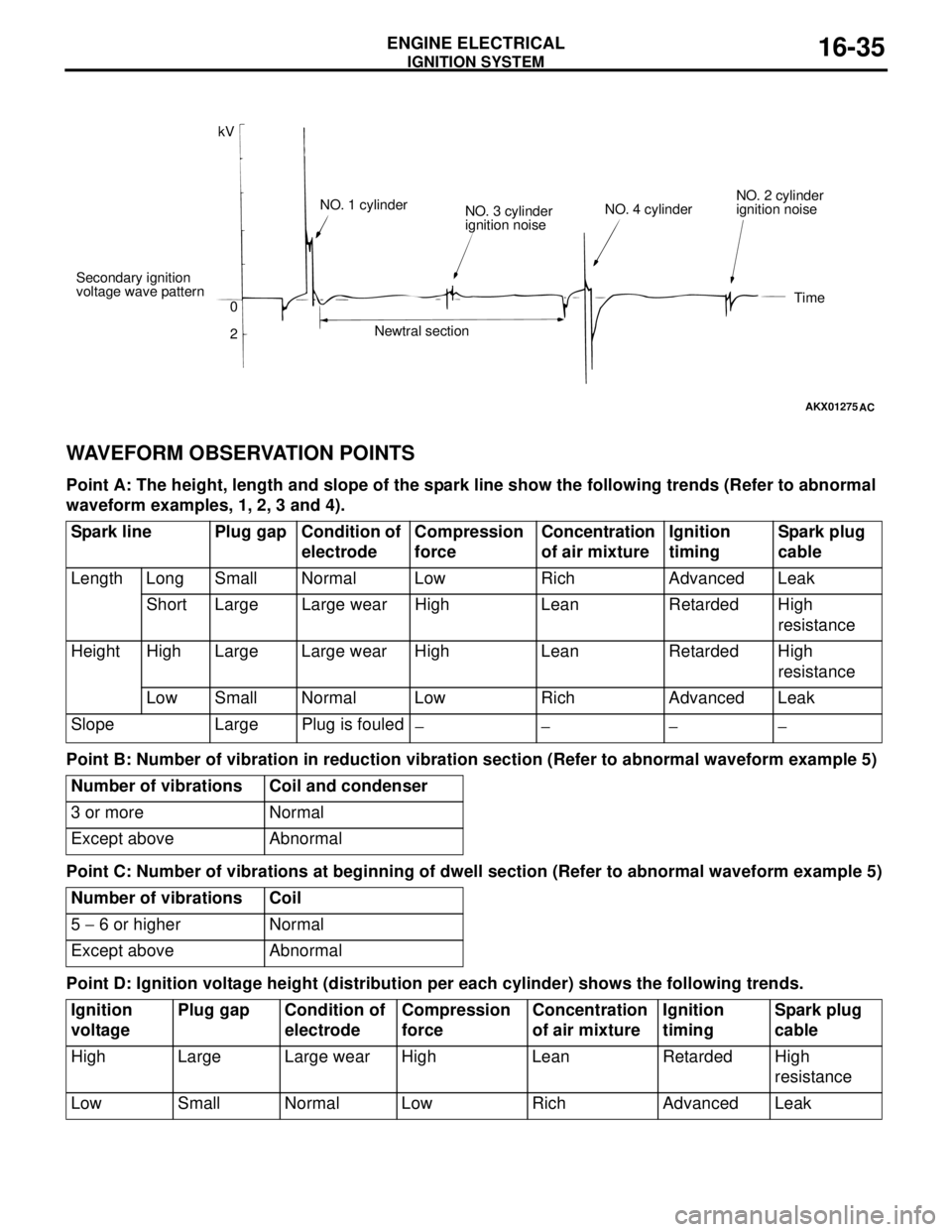
WAVEFORM OBSERVATION POINTS
Point A: The height, length and slope of the spark line show the following trends (Refer to abnormal
waveform examples, 1, 2, 3 and 4).
Point B: Number of vibration in reduction vibration section (Refer to abnormal waveform example 5)
Point C: Number of vibrations at beginning of dwell section (Refer to abnormal waveform example 5)
Point D: Ignition voltage height (distribution per each cylinder) shows the following trends.
AKX01275
kV
Secondary ignition
voltage wave pattern
0
2NO. 1 cylinder
NO. 3 cylinder
ignition noise
Newtral sectionNO. 4 cylinderNO. 2 cylinder
ignition noise
Time
AC
Spark line Plug gap Condition of
electrodeCompression
force Concentration
of air mixtureIgnition
timingSpark plug
cable
Length Long Small Normal Low Rich Advanced Leak
Short Large Large wear High Lean Retarded High
resistance
Height High Large Large wear High Lean Retarded High
resistance
Low Small Normal Low Rich Advanced Leak
Slope Large Plug is fouled
−− −−
Number of vibrations Coil and condenser
3 or more Normal
Except above Abnormal
Number of vibrations Coil
5 − 6 or higher Normal
Except above Abnormal
Ignition
voltagePlug gap Condition of
electrodeCompression
forceConcentration
of air mixtureIgnition
timingSpark plug
cable
High Large Large wear High Lean Retarded High
resistance
Low Small Normal Low Rich Advanced Leak
Page 113 of 788

EMISSION CONTROL
ENGINE AND EMISSION CONTROL17-5
EMISSION CONTROL
GENERAL INFORMATIONM1173000100370
The emission control system consists of the following
subsystems:•Crankcase emission control system
•Evaporative emission control system
•Exhaust emission control system
EMISSION CONTROL DEVICE
REFERENCE TABLE
M1173006600135
SERVICE SPECIFICATION(S)M1173000300288
Items Name Specification
Crankcase emission control
systemPositive crankcase ventilation
(PCV) valveVariable flow type
(Purpose: HC reduction)
Evaporative emission control
systemCanister
Purge control solenoid valveEquipped
Duty cycle type solenoid valve
(Purpose: HC reduction)
Exhaust emission control system Air-fuel ratio control device - MPI
systemOxygen sensor feedback type
(Purpose: CO, HC, NOx reduction)
Exhaust gas recirculation system
•EGR valve
•EGR control solenoid valveEquipped
Single type
Duty cycle type solenoid valve
(Purpose: NOx reduction)
Catalytic converter Monolith type
(Purpose: CO, HC, NOx reduction)
Related parts Crankcase
emission
control
systemEvaporative
emission
control
systemAir/fuel ratio
control
systemCatalytic
converterExhaust gas
recirculation
system
PCV valve
×
Purge control solenoid valve
×
MPI system component
××
Catalytic converter
×
EGR valve
×
EGR control solenoid valve
×
Items Standard value
Purge control solenoid valve coil resistance (at 20°C) Ω30 − 34
EGR control solenoid valve coil resistance (at 20°C) Ω29 − 35
Page 114 of 788
EMISSION CONTROL
ENGINE AND EMISSION CONTROL17-6
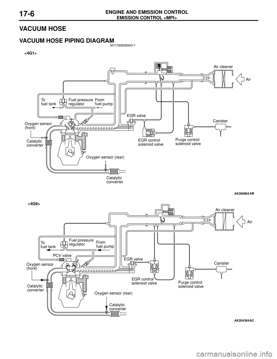
VACUUM HOSE
VACUUM HOSE PIPING DIAGRAMM1173000900417
AK300964
To
fuel tankFuel pressure
regulatorFrom
fuel pump
Catalytic
converter
Catalytic
converter Oxygen sensor
(front)
Oxygen sensor (rear)EGR valve <4G1>
EGR control
solenoid valvePurge control
solenoid valveCanisterAir
AB
Air cleaner
AK204364
AC
Air cleaner
Air
Canister
Purge control
solenoid valve EGR control
solenoid valve EGR valve From
fuel pump To
fuel tankFuel pressure
regulator
PCV valve
Oxygen sensor
(front)
Oxygen sensor (rear) Catalytic
converter
Catalytic
converter
<4G6>
Page 115 of 788
EMISSION CONTROL
ENGINE AND EMISSION CONTROL17-7
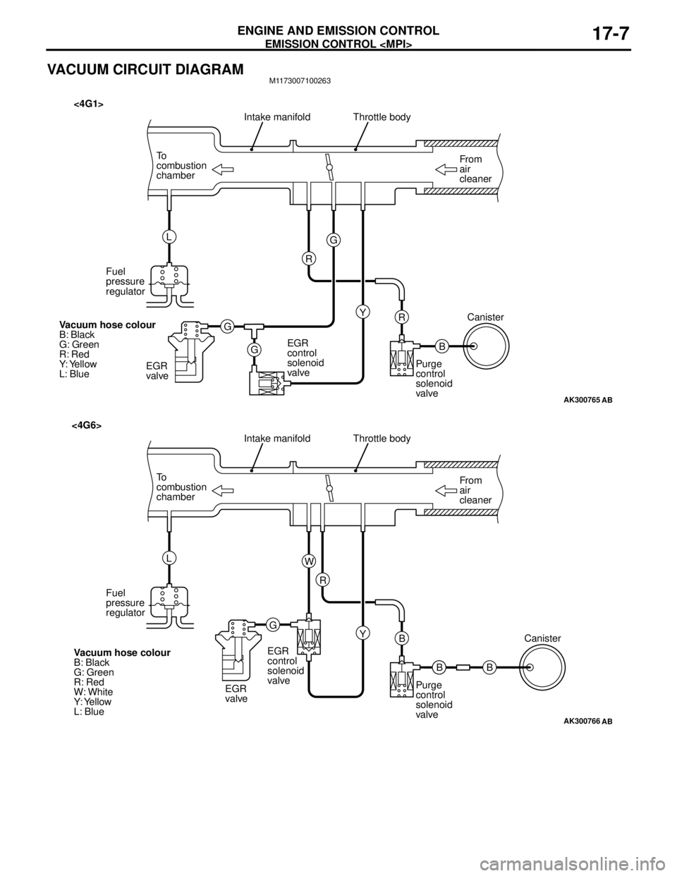
VACUUM CIRCUIT DIAGRAMM1173007100263
AK300765
From
air
cleaner To
combustion
chamberThrottle body
B R
AB
Intake manifold
Y G
G
GR L
Fuel
pressure
regulator
EGR
valveEGR
control
solenoid
valvePurge
control
solenoid
valveCanister
Vacuum hose colour
B: Black
G: Green
R: Red
Y: Yellow
L: Blue
<4G1>
AK300766
From
air
cleaner To
combustion
chamberThrottle body
B B
AB
Intake manifold
Y R
GW L
Fuel
pressure
regulator
EGR
valveEGR
control
solenoid
valve
Purge
control
solenoid
valveCanister
Vacuum hose colour
B: Black
G: Green
R: Red
W: White
Y: Yellow
L: Blue
<4G6>
B
Page 116 of 788
EMISSION CONTROL
ENGINE AND EMISSION CONTROL17-8
VACUUM HOSE CHECKM1173007300159
1. Using the piping diagram as a guide, check to be
sure that the vacuum hoses are correctly
connected.
2. Check the connection condition of the vacuum
hoses, (removed, loose, etc.) and check to be
sure that there are no bends or damage.
VACUUM HOSE INSTALLATIONM1173007200107
1. When connecting the vacuum hoses, they should
be securely inserted onto the nipples.
2. Connect the hoses correctly, using the vacuum
hose piping diagram as a guide.
CRANKCASE EMISSION CONTROL
SYSTEM
GENERAL INFORMATION (CRANKCASE
EMISSION CONTROL SYSTEM)
M1173005000237
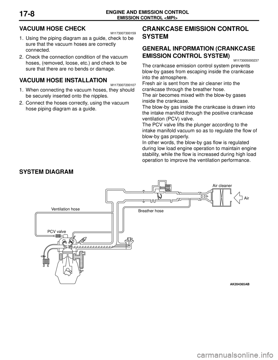
The crankcase emission control system prevents
blow-by gases from escaping inside the crankcase
into the atmosphere.
Fresh air is sent from the air cleaner into the
crankcase through the breather hose.
The air becomes mixed with the blow-by gases
inside the crankcase.
The blow-by gas inside the crankcase is drawn into
the intake manifold through the positive crankcase
ventilation (PCV) valve.
The PCV valve lifts the plunger according to the
intake manifold vacuum so as to regulate the flow of
blow-by gas properly.
In other words, the blow-by gas flow is regulated
during low load engine operation to maintain engine
stability, while the flow is increased during high load
operation to improve the ventilation performance.
SYSTEM DIAGRAM
AK204365
Air cleaner
Air
Ventilation hose
Breather hose
PCV valve
AB