Air con MITSUBISHI LANCER 2005 Repair Manual
[x] Cancel search | Manufacturer: MITSUBISHI, Model Year: 2005, Model line: LANCER, Model: MITSUBISHI LANCER 2005Pages: 788, PDF Size: 45.98 MB
Page 250 of 788
ON-VEHICLE SERVICE
POWER STEERING37-16
WARNING
•If the vehicle continues to be driven after
the collision absorbing mechanism has
operated, the steering column shaft may
be damaged while it is in use.
•If there is a slack in the one-way capsule,
do not attempt to repair it but replace the
steering column shaft assembly.
Inspection Procedure
1. Remove the lower and upper column covers.
CAUTION
Do not release the tilt lever until the steering
column has been installed to complete this
inspection procedure.
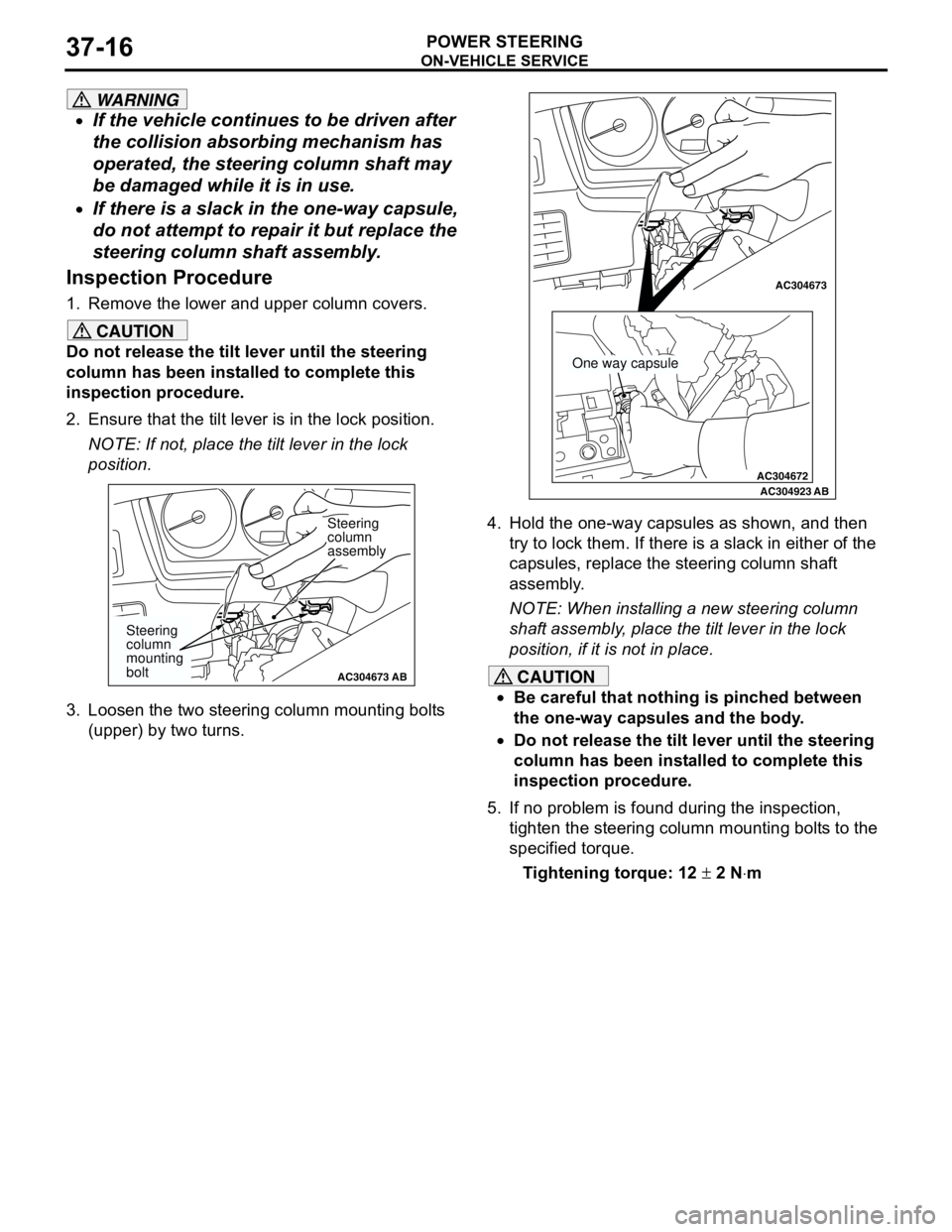
2. Ensure that the tilt lever is in the lock position.
NOTE: If not, place the tilt lever in the lock
position.
3. Loosen the two steering column mounting bolts
(upper) by two turns.4. Hold the one-way capsules as shown, and then
try to lock them. If there is a slack in either of the
capsules, replace the steering column shaft
assembly.
NOTE: When installing a new steering column
shaft assembly, place the tilt lever in the lock
position, if it is not in place.
CAUTION
•Be careful that nothing is pinched between
the one-way capsules and the body.
•Do not release the tilt lever until the steering
column has been installed to complete this
inspection procedure.
5. If no problem is found during the inspection,
tighten the steering column mounting bolts to the
specified torque.
Tightening torque: 12 ± 2 N⋅m
AC304673AC304673
Steering
column
assembly
AB
Steering
column
mounting
bolt
AC304672
AC304673AC304673
AC304923AB
One way capsule
Page 252 of 788
Page 254 of 788
STEERING WHEEL
POWER STEERING37-20
<> STEERING WHEEL AND AIRBAG
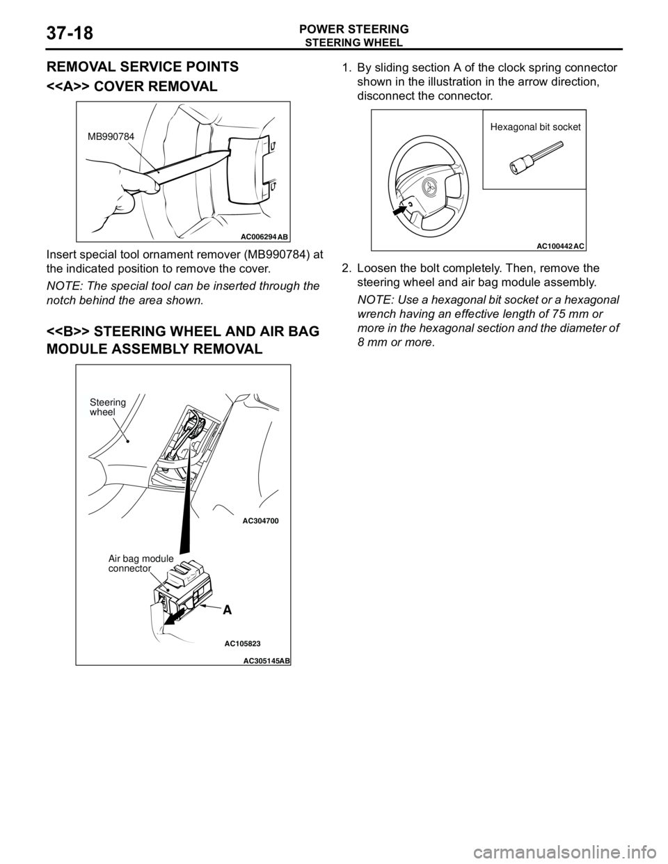
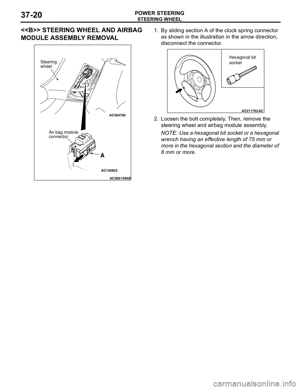
MODULE ASSEMBLY REMOVAL1. By sliding section A of the clock spring connector
as shown in the illustration in the arrow direction,
disconnect the connector.
2. Loosen the bolt completely. Then, remove the
steering wheel and airbag module assembly.
NOTE: Use a hexagonal bit socket or a hexagonal
wrench having an effective length of 75 mm or
more in the hexagonal section and the diameter of
8 mm or more.
AC105823
AC304700
AC305145AB
A
Steering
wheel
Air bag module
connector
AC211762AC
Hexagonal bit
socket
Page 255 of 788
STEERING SHAFT
POWER STEERING37-21
STEERING SHAFT
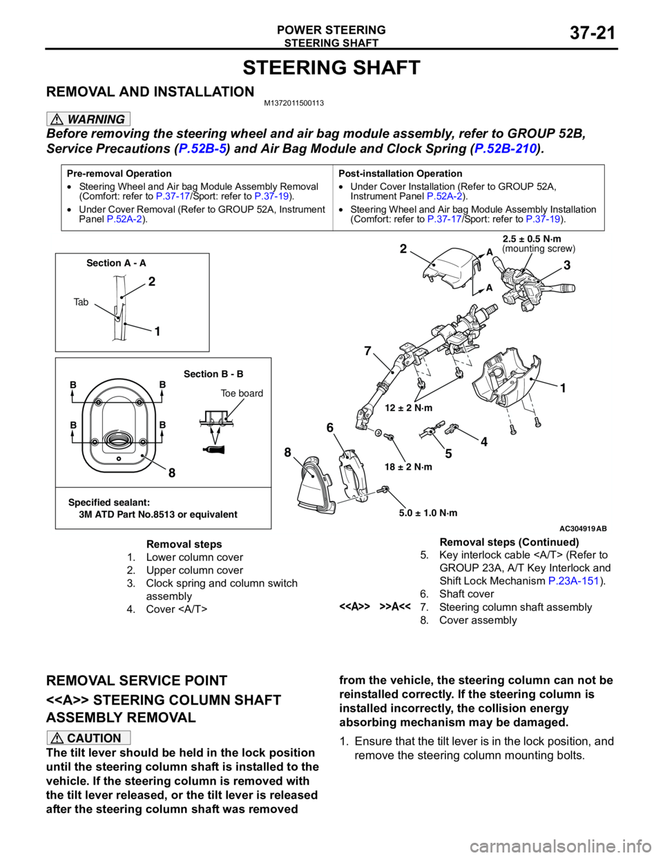
REMOVAL AND INSTALLATIONM1372011500113
WARNING
Before removing the steering wheel and air bag module assembly, refer to GROUP 52B,
Service Precautions (P.52B-5) and Air Bag Module and Clock Spring (P.52B-210).
REMOVAL SERVICE POINT
<> STEERING COLUMN SHAFT
ASSEMBLY REMOVAL
CAUTION
The tilt lever should be held in the lock position
until the steering column shaft is installed to the
vehicle. If the steering column is removed with
the tilt lever released, or the tilt lever is released
after the steering column shaft was removed from the vehicle, the steering column can not be
reinstalled correctly. If the steering column is
installed incorrectly, the collision energy
absorbing mechanism may be damaged.
1. Ensure that the tilt lever is in the lock position, and
remove the steering column mounting bolts.
Pre-removal Operation
•Steering Wheel and Air bag Module Assembly Removal
(Comfort: refer to P.37-17/Sport: refer to P.37-19).
•Under Cover Removal (Refer to GROUP 52A, Instrument
Panel P.52A-2).Post-installation Operation
•Under Cover Installation (Refer to GROUP 52A,
Instrument Panel P.52A-2).
•Steering Wheel and Air bag Module Assembly Installation
(Comfort: refer to P.37-17/Sport: refer to P.37-19).
AC304919AB
12 ± 2 N·m
18 ± 2 N·m
5.0 ± 1.0 N·m
1 2
73 2
1
8
86
A
A
Ta bSection A - A
Section B - B
BB
Toe board
Specified sealant:
3M ATD Part No.8513 or equivalent
BB
4
5
(mounting screw)2.5 ± 0.5 N·m
Removal steps
1. Lower column cover
2. Upper column cover
3. Clock spring and column switch
assembly
4. Cover 5. Key interlock cable (Refer to
GROUP 23A, A/T Key Interlock and
Shift Lock Mechanism P.23A-151).
6. Shaft cover
<> >>A<<7. Steering column shaft assembly
8. Cover assemblyRemoval steps (Continued)
Page 258 of 788
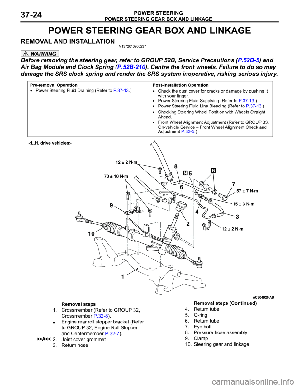
POWER STEERING GEAR BOX AND LINKAGE
POWER STEERING37-24
POWER STEERING GEAR BOX AND LINKAGE
REMOVAL AND INSTALLATIONM1372010900237
WARNING
Before removing the steering gear, refer to GROUP 52B, Service Precautions (P.52B-5) and
Air Bag Module and Clock Spring (P.52B-210). Centre the front wheels. Failure to do so may
damage the SRS clock spring and render the SRS system inoperative, risking serious injury.
Pre-removal Operation
•Power Steering Fluid Draining (Refer to P.37-13.)Post-installation Operation
•Check the dust cover for cracks or damage by pushing it
with your finger.
•Power Steering Fluid Supplying (Refer to P.37-13.)
•Power Steering Fluid Line Bleeding (Refer to P.37-13.)
•Checking Steering Wheel Position with Wheels Straight
Ahead.
•Front Wheel Alignment Adjustment (Refer to GROUP 33,
On-vehicle Service − Front Wheel Alignment Check and
Adjustment P.33-5.)
AC304920
AB
57 ± 7 N·m
15 ± 3 N·m 70 ± 10 N·m
7
3 8
5
6
9
1024
1
12 ± 2 N·m
12 ± 2 N·m
Removal steps
1. Crossmember (Refer to GROUP 32,
Crossmember P.32-8).
•Engine rear roll stopper bracket (Refer
to GROUP 32, Engine Roll Stopper
and Centermember P.32-7).
>>A<<2. Joint cover grommet
3. Return hose4. Return tube
5. O-ring
6. Return tube
7. Eye bolt
8. Pressure hose assembly
9. Clamp
10. Steering gear and linkageRemoval steps (Continued)
Page 261 of 788
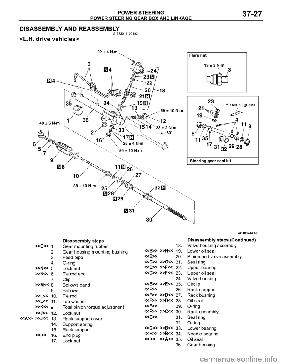
POWER STEERING GEAR BOX AND LINKAGE
POWER STEERING37-27
DISASSEMBLY AND REASSEMBLYM1372011100193
AC100244AE
3
13 ± 3 N·m
Steering gear seal kit Flare nut
Repair kit grease
23
21
19
4
11
8
28 29
32 31 17 35
11 8
22 ± 4 N·m
59 ± 10 N·m
23 ± 2 N·m
-30˚
12
14
15
33
17
59 ± 10 N·m25 ± 4 N·m
18 24
23
20
19
2122
13 344
4
3
35
136
2
16
30 31
32
27
29 28
2526 1188 ± 10 N·m
10 8
9 7 5 6
40 ± 5 N·m
Disassembly steps
>>O<<1. Gear mounting rubber
2. Gear housing mounting bushing
3. Feed pipe
4. O-ring
>>N<<5. Lock nut
>>N<<6. Tie rod end
7. Clip
>>M<<8. Bellows band
9. Bellows
>>L<<10. Tie rod
>>L<<11. Tab washer
>>K<<•Total pinion torque adjustment
>>J<<12. Lock nut
<> >>J<<13. Rack support cover
14. Support spring
15. Rack support
>>I<<16. End plug
17. Lock nut18. Valve housing assembly
<> >>H<<19. Lower oil seal
<>20. Pinion and valve assembly
<
<
<
24. Valve housing
<
<
<
<
<
<
<
32. O-ring
<
<
<> >>A<<35. Oil seal
36. Gear housingDisassembly steps (Continued)
Page 262 of 788
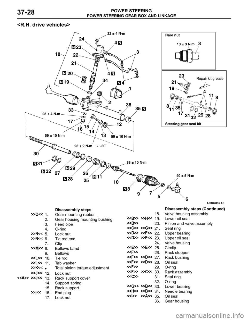
POWER STEERING GEAR BOX AND LINKAGE
POWER STEERING37-28
AC102865
3
23
21
19
4
11
8
8
1135
17
31
3229
28
6 5 7
9 8 10 11
25 26
2829
27 32 31 3012
13 14 15
16 173335 361 4
2 3444
3 24
23
22
21
20
19
18
AE
Steering gear seal kit Flare nut
Repair kit grease 22 ± 4 N·m
59 ± 10 N·m 25 ± 4 N·m
88 ± 10 N·m
40 ± 5 N·m 59 ± 10 N·m13 ± 3 N·m
23 ± 2 N·m -30˚
Disassembly steps
>>O<<1. Gear mounting rubber
2. Gear housing mounting bushing
3. Feed pipe
4. O-ring
>>N<<5. Lock nut
>>N<<6. Tie rod end
7. Clip
>>M<<8. Bellows band
9. Bellows
>>L<<10. Tie rod
>>L<<11. Tab washer
>>K<<•Total pinion torque adjustment
>>J<<12. Lock nut
<> >>J<<13. Rack support cover
14. Support spring
15. Rack support
>>I<<16. End plug
17. Lock nut18. Valve housing assembly
<> >>H<<19. Lower oil seal
<>20. Pinion and valve assembly
<
<
<
24. Valve housing
<
<
<
<
<
<
<
32. O-ring
<
<
<> >>A<<35. Oil seal
36. Gear housingDisassembly steps (Continued)
Page 263 of 788
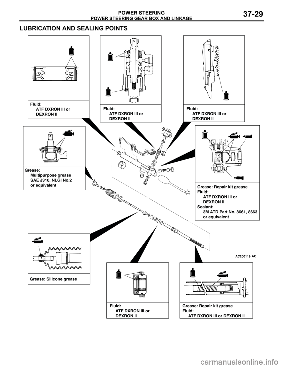
POWER STEERING GEAR BOX AND LINKAGE
POWER STEERING37-29
LUBRICATION AND SEALING POINTS
AC200119AC
Grease: Silicone greaseFluid:
ATF DXRON III or
DEXRON II
Grease: Repair kit grease
Fluid:
ATF DXRON III or
DEXRON II
Sealant:
3M ATD Part No. 8661, 8663
or equivalent Grease:
Multipurpose grease
SAE J310, NLGI No.2
or equivalent
Fluid:
ATF DXRON III or
DEXRON IIFluid:
ATF DXRON III or
DEXRON II
Fluid:
ATF DXRON III or
DEXRON IIGrease: Repair kit grease
Fluid:
ATF DXRON III or DEXRON II
Page 276 of 788
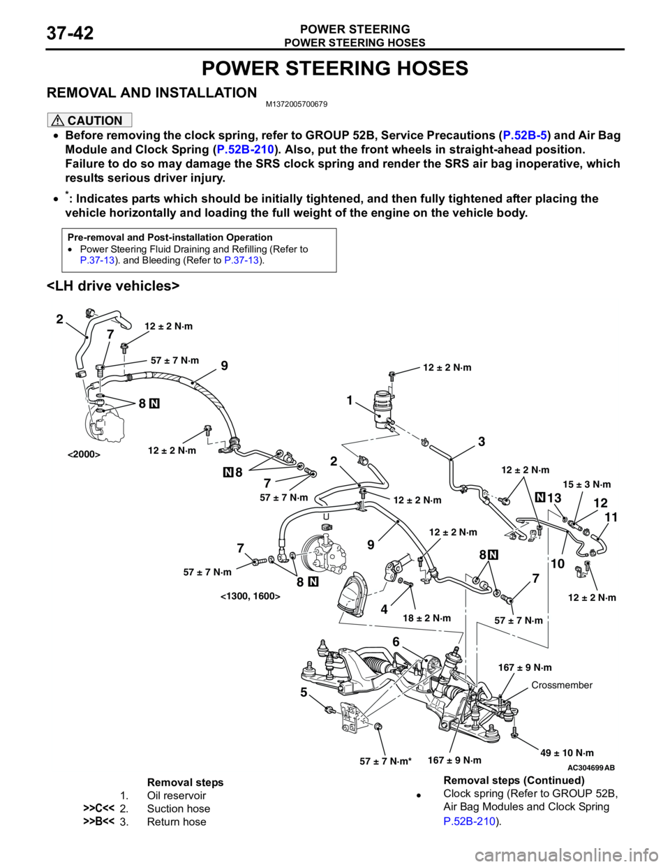
POWER STEERING HOSES
POWER STEERING37-42
POWER STEERING HOSES
REMOVAL AND INSTALLATIONM1372005700679
CAUTION
•Before removing the clock spring, refer to GROUP 52B, Service Precautions (P.52B-5) and Air Bag
Module and Clock Spring (P.52B-210). Also, put the front wheels in straight-ahead position.
Failure to do so may damage the SRS clock spring and render the SRS air bag inoperative, which
results serious driver injury.
•
*: Indicates parts which should be initially tightened, and then fully tightened after placing the
vehicle horizontally and loading the full weight of the engine on the vehicle body.
Pre-removal and Post-installation Operation
•Power Steering Fluid Draining and Refilling (Refer to
P.37-13). and Bleeding (Refer to P.37-13).
AC304699AB
15 ± 3 N·m
18 ± 2 N·m
167 ± 9 N·m 12 ± 2 N·m
49 ± 10 N·m 12 ± 2 N·m
57 ± 7 N·m*57 ± 7 N·m
3 1
2
9
13
10
711 12
568
12 ± 2 N·m12 ± 2 N·m
2
9
4 7 8
7 8
7
8
57 ± 7 N·m57 ± 7 N·m 57 ± 7 N·m
12 ± 2 N·m
167 ± 9 N·m
Crossmember 12 ± 2 N·m
<1300, 1600> <2000>
12 ± 2 N·m
Removal steps
1. Oil reservoir
>>C<<2. Suction hose
>>B<<3. Return hose•Clock spring (Refer to GROUP 52B,
Air Bag Modules and Clock Spring
P.52B-210). Removal steps (Continued)
Page 277 of 788
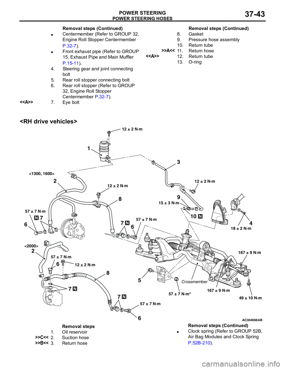
POWER STEERING HOSES
POWER STEERING37-43
•Centermember (Refer to GROUP 32,
Engine Roll Stopper Centermember
P.32-7).
•Front exhaust pipe (Refer to GROUP
15, Exhaust Pipe and Main Muffler
P.15-11).
4. Steering gear and joint connecting
bolt
5. Rear roll stopper connecting bolt
6. Rear roll stopper (Refer to GROUP
32, Engine Roll Stopper
Centermember P.32-7).
<>7. Eye boltRemoval steps (Continued)
8. Gasket
9. Pressure hose assembly
10. Return tube
>>A<<11. Return hose
<>12. Return tube
13. O-ringRemoval steps (Continued)
AC304698AB
15 ± 3 N·m
18 ± 2 N·m
167 ± 9 N·m 12 ± 2 N·m
49 ± 10 N·m 12 ± 2 N·m
57 ± 7 N·m*
3 1
2
9
10
7
5 6
24
8857 ± 7 N·m
167 ± 9 N·m
Crossmember12 ± 2 N·m <1300, 1600>
<2000>
7
6
57 ± 7 N·m
7 6
57 ± 7 N·m
7
6
57 ± 7 N·m
12 ± 2 N·m
Removal steps
1. Oil reservoir
>>C<<2. Suction hose
>>B<<3. Return hose•Clock spring (Refer to GROUP 52B,
Air Bag Modules and Clock Spring
P.52B-210). Removal steps (Continued)